MPLS Quality of Service (QoS)
Available Languages
Table Of Contents
Tag Switching/MPLS Terminology
MPLS CoS: LSRs Used at the Edge of an MPLS Network
MPLS CoS: LSRs Used at the Core of an MPLS Network
Benefits of MPLS CoS in IP Backbones
Verifying the CAR Configuration
Verifying the CBWFQ Configuration
Configuration Examples for MPLS QoS
Example: Configuring Cisco Express Forwarding
Example: Running IP on Router 1
Example: Running MPLS on Router 2
Example: Running MPLS on Router 3
Example: Running MPLS on Router 4
Example: Running MPLS on Router 5
Example: Running IP on Router 6
Feature Information for MPLS Quality of Service
MPLS Quality of Service (QoS)
This document describes the use of the MPLS class of service (CoS) functionality in an MPLS network.

Note
MPLS Class of Service is referred to as MPLS Quality of Service (QoS). This name reflects the growth of MPLS to encompass a wider meaning and highlight the path towards future enhancements.
Finding Feature Information
Your software release may not support all the features documented in this module. For the latest feature information and caveats, see the release notes for your platform and software release. To find information about the features documented in this module, and to see a list of the releases in which each feature is supported, see the "Feature Information for MPLS Quality of Service" section.
Use Cisco Feature Navigator to find information about platform support and Cisco software image support. To access Cisco Feature Navigator, go to http://www.cisco.com/go/cfn. An account on Cisco.com is not required.
Contents
•
•
Prerequisites for MPLS QoS
To use MPLS CoS to full advantage in your network, the following functionality must be supported:
•
•
•
Note
•
–
WFQ applies priorities, or weights, to traffic to classify the traffic into flows and determine how much bandwidth to allow each flow. WFQ moves interactive traffic to the front of a queue to reduce response time and fairly shares the remaining bandwidth among high-bandwidth flows.
–
IP precedence bits, contained in the type of service (ToS) octet in the IP packet header, are used to denote the relative importance or priority of an IP packet. WRED uses these IP precedence values to classify packets into different discard priorities or classes of service.
–
Information About MPLS QoS
•
•
•
•
MPLS QoS Overview
MPLS CoS functionality enables network administrators to provide differentiated services across an MPLS network. Network administrators can satisfy a wide range of networking requirements by specifying the class of service applicable to each transmitted IP packet. Different classes of service can be established for IP packets by setting the IP precedence bit in the header of each packet.
MPLS CoS supports the following differentiated services in an MPLS network:
•
•
•
Table 1 describes the MPLS CoS services and functions.
MPLS CoS enables you to duplicate Cisco IOS XE IP CoS (Layer 3) features as closely as possible in MPLS devices, including label edge switch routers (edge LSRs) and label switch routers (LSRs). MPLS CoS functions map nearly one-for-one to IP CoS functions on all types of interfaces.
Tag Switching/MPLS Terminology
Table 2 lists the existing legacy tag switching terms and the new, equivalent MPLS IETF terms used in this document and other related Cisco publications.
MPLS CoS: LSRs Used at the Edge of an MPLS Network
LSRs used at the edge of an MPLS network backbone are routers running MPLS software. The edge LSRs can be at the ingress or the egress of the network.
At the ingress of an MPLS network, routers process packets as follows:
1.
2.
3.
4.
5.
6.
–
–
In either case, LSRs enforce the defined differentiation by continuing to employ WRED or CBWFQ on every ingress router.
At the egress of an MPLS network, routers process packets as follows:
1.
2.
3.
4.
MPLS CoS: LSRs Used at the Core of an MPLS Network
LSRs used at the core of an MPLS network are routers running MPLS software. These routers at the core of an MPLS network process packets as follows:
1.
2.
3.
4.
5.
Benefits of MPLS CoS in IP Backbones
You realize the following benefits when you use MPLS CoS in a backbone consisting of IP routers running MPLS:
•
•
•
How to Configure MPLS QoS
This section contains the procedures listed below. All the procedures are listed as optional. However, once you decide to configure a specific MPLS QoS feature (for example, WRED) that procedure becomes required.
•
•
•
•
•
•
Configuring WRED
To configure weighted random early detection (WRED), use the commands shown in the following table.
DETAILED STEPS
Verifying WRED
To verify weighted random early detection (WRED), use a command of the form shown in the following table. This example is based on "Router2" in the network topology shown in Figure 1.
Step 1
show queueing interface subinterface
Router2#show queueing interface gigabitethernet6/0/0Interface Gige6/0/0 queueing strategy:random early detection (WRED)Exp-weight-constant:9 (1/512)Mean queue depth:0Class Random Tail Minimum Maximum Markdrop drop threshold threshold probability0 85 0 20 40 1/101 22 0 22 40 1/102 0 0 24 40 1/103 0 0 26 40 1/104 0 0 28 40 1/105 0 0 31 40 1/106 0 0 33 40 1/107 0 0 35 40 1/10rsvp 0 0 37 40 1/10
Configuring CAR
DETAILED STEPS
Verifying the CAR Configuration
To verify weighted random early detection (WRED), use a command of the form shown in the following table. This example is based on "Router2" in the network topology shown in Figure 1.
Step 1
To verify the CAR configuration, use a command of the following form. This example is based on "Router 2" in the network topology shown in Figure 1.
Router2# show interfaces fe1/1/1 rate-limitFastEthernet1/1/1Inputmatches:access-group 101params: 496000 bps, 32000 limit, 64000 extended limitconformed 2137 packets, 576990 bytes; action:set-prec-transmit 4exceeded 363 packets, 98010 bytes; action:set-prec-transmit 0last packet:11788ms ago, current burst:39056 byteslast cleared 00:01:18 ago, conformed 58000 bps, exceeded 10000 bps
Configuring CBWFQ
DETAILED STEPS
Verifying the CBWFQ Configuration
Step 1
To verify the CBWFQ configuration, use a command of the following form. This example is based on "Router 5" in the network topology shown in Figure 1.
Router5# show policy-map interface fe5/1/0FastEthernet5/1/0service-policy output:outputmapclass-map:prec_01 (match-all)522 packets, 322836 bytes5 minute rate 1000 bpsmatch:ip precedence 0 1queue size 0, queue limit 1356packet output 522, packet drop 0tail/random drop 0, no buffer drop 0, other drop 0bandwidth:class-based wfq, weight 10random-detect:Exp-weight-constant:9 (1/512)Mean queue depth:0Class Random Tail Minimum Maximum Mark Outputdrop drop threshold threshold probability packets0 0 0 3390 6780 1/10 5221 0 0 3813 6780 1/10 02 0 0 4236 6780 1/10 03 0 0 4659 6780 1/10 04 0 0 5082 6780 1/10 05 0 0 5505 6780 1/10 06 0 0 5928 6780 1/10 07 0 0 6351 6780 1/10 0class-map:prec_23 (match-all)0 packets, 0 bytes5 minute rate 0 bpsmatch:ip precedence 2 3queue size 0, queue limit 0packet output 0, packet drop 0tail/random drop 0, no buffer drop 0, other drop 0bandwidth:class-based wfq, weight 15random-detect:Exp-weight-constant:9 (1/512)Mean queue depth:0Class Random Tail Minimum Maximum Mark Outputdrop drop threshold threshold probability packets0 0 0 0 0 1/10 01 0 0 0 0 1/10 02 0 0 0 0 1/10 03 0 0 0 0 1/10 04 0 0 0 0 1/10 05 0 0 0 0 1/10 06 0 0 0 0 1/10 07 0 0 0 0 1/10 0class-map:prec_45 (match-all)2137 packets, 576990 bytes5 minute rate 16000 bpsmatch:ip precedence 4 5queue size 0, queue limit 2712packet output 2137, packet drop 0tail/random drop 0, no buffer drop 0, other drop 0bandwidth:class-based wfq, weight 20random-detect:Exp-weight-constant:9 (1/512)Mean queue depth:0Class Random Tail Minimum Maximum Mark Outputdrop drop threshold threshold probability packets0 0 0 3390 6780 1/10 01 0 0 3813 6780 1/10 02 0 0 4236 6780 1/10 03 0 0 4659 6780 1/10 04 0 0 5082 6780 1/10 21375 0 0 5505 6780 1/10 06 0 0 5928 6780 1/10 07 0 0 6351 6780 1/10 0class-map:prec_67 (match-all)0 packets, 0 bytes5 minute rate 0 bpsmatch:ip precedence 6 7queue size 0, queue limit 0packet output 0, packet drop 0tail/random drop 0, no buffer drop 0, other drop 0bandwidth:class-based wfq, weight 25random-detect:Exp-weight-constant:9 (1/512)Mean queue depth:0Class Random Tail Minimum Maximum Mark Outputdrop drop threshold threshold probability packets0 0 0 0 0 1/10 01 0 0 0 0 1/10 02 0 0 0 0 1/10 03 0 0 0 0 1/10 04 0 0 0 0 1/10 05 0 0 0 0 1/10 06 0 0 0 0 1/10 07 0 0 0 0 1/10 0class-map:class-default (match-any)0 packets, 0 bytes5 minute rate 0 bpsmatch:any0 packets, 0 bytes5 minute rate 0 bpsqueue size 0, queue limit 4068packet output 90, packet drop 0tail/random drop 0, no buffer drop 0, other drop 0Router5#Router5# show queueing interface fa1/1/0Interface FastEthernet1/1/0 queueing strategy:VIP-based fair queueingFastEthernet1/1/0 queue size 0pkts output 2756, wfq drops 0, nobuffer drops 0WFQ:aggregate queue limit 13561 max available buffers 13561Class 0:weight 30 limit 4068 qsize 0 pkts output 97 drops 0Class 2:weight 10 limit 1356 qsize 0 pkts output 522 drops 0Class 3:weight 15 limit 0 qsize 0 pkts output 0 drops 0Class 4:weight 20 limit 2712 qsize 0 pkts output 2137 drops 0Class 5:weight 25 limit 0 qsize 0 pkts output 0 drops 0 \
Configuration Examples for MPLS QoS
•
•
•
•
•
•
•
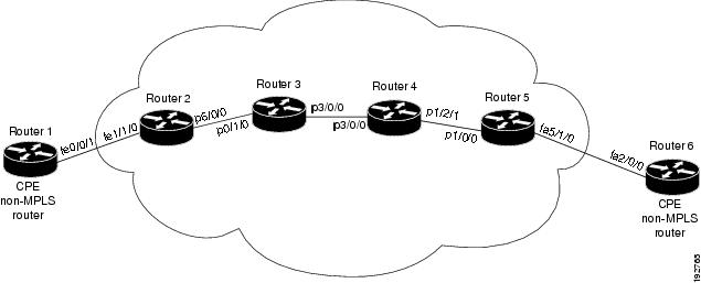
The configuration examples in this section are based on the sample network topology shown in Figure 1.
Figure 1 Sample Network Topology for Configuring MPLS CoS on Router Interfaces
Example: Configuring Cisco Express Forwarding
Cisco Express Forwarding is a prerequisite for using MPLS CoS; CEF must be running on all routers and switches in the MPLS network. To enable Cisco Express Forwarding on a router or a switch, use the following command:
Router(config)#ip cefExample: Running IP on Router 1
The following commands enable IP routing on Router 1 (see Figure 1). All routers in Figure 1 must have IP enabled.
Note
!ip routing!hostname R1!interface Loopback0ip address 10.1.1.1 255.255.255.255!interface FastEthernet0/0/1ip address 10.0.0.1 255.0.0.0!router ospf 100network 10.0.0.0 0.255.255.255 area 100network 10.0.0.1 0.255.255.255 area 100Example: Running MPLS on Router 2
Router 2 (see Figure 1) is a label edge router. Cisco Express Forwarding and MPLS must be enabled on this router. CAR is also configured on Router 2 and interface e1/3. The CAR policy used at FastEthernet interface 1/1/0 acts on incoming traffic matching access-list 101. If the traffic rate is less than the committed information rate (in this example, 496000), the traffic will be sent with IP precedence 4. Otherwise, this traffic will be sent with IP precedence 0.
!ip routing!hostname R2!ip cefmpls iptag-switching advertise-tags!interface Loopback0ip address 10.10.10.10 255.255.255.255!interface FastEthernet1/1/0ip address 10.0.0.2 255.0.0.0rate-limit input access-group 101 496000 32000 64000 conform-action set-prec-transmit 4 exceed-action set-prec-transmit 0!interface POS6/0/0ip address 10.0.0.1 255.0.0.0mpls label protocol ldpmpls iprandom-detectclock source internal!router ospf 100network 10.0.0.0 0.255.255.255 area 100network 10.1.0.0 0.255.255.255 area 100network 11.0.1.0 0.255.255.255 area 100!access-list 101 permit ip host 10.10.1.1 anyExample: Running MPLS on Router 3
Router 3 (see Figure 1) is running MPLS. Cisco Express Forwarding and MPLS must be enabled on this router.
!ip routingmpls iptag-switching advertise-tags!hostname R3!interface Loopback0ip address 10.10.10.10 255.255.255.255!interface POS0/1/0ip address 10.0.0.2 255.0.0.0mpls label protocol ldpmpls ipcrc 16!interface POS3/0/0ip address 10.0.0.1 255.0.0.0mpls label protocol ldpmpls ipcrc 16clock source internaltx-cos stm16-rx!router ospf 100network 10.0.1.0 0.255.255.255 area 100network 10.0.0.1 0.255.255.255 area 100network 10.1.0.0 0.255.255.255 area 100!cos-queue-group stm16-rxprecedence 0 random-detect-label 0precedence 0 queue 0precedence 1 queue 1precedence 1 random-detect-label 1precedence 2 queue 2precedence 2 random-detect-label 2precedence 3 random-detect-label 2precedence 4 random-detect-label 2precedence 5 random-detect-label 2precedence 6 random-detect-label 2precedence 7 queue low-latencyprecedence 7 random-detect-label 2random-detect-label 0 250 1000 1random-detect-label 1 500 1250 1random-detect-label 2 750 1500 1queue 0 50queue 1 100queue 2 150queue low-latency alternate-priority 500Example: Running MPLS on Router 4
Router 4 (see Figure 1) is running MPLS. Cisco Express Forwarding and MPLS must be enabled on this router.
!ip routingmpls iptag-switching advertise-tags!hostname R4!interface Loopback0ip address 10.0.0.0 255.255.255.255!interface POS1/2/1ip address 10.0.0.1 255.0.0.0mpls label protocol ldpmpls ipcrc 16clock source internaltx-cos stm16-rx!router ospf 100network 10.0.0.0 0.255.255.255 area 100network 10.1.0.0 0.255.255.255 area 100network 10.0.1.0 0.255.255.255 area 100!cos-queue-group stm16-rxprecedence 0 queue 0precedence 0 random-detect-label 0precedence 1 queue 1precedence 1 random-detect-label 1precedence 2 queue 2precedence 2 random-detect-label 2precedence 3 random-detect-label 2precedence 4 random-detect-label 2precedence 5 random-detect-label 2precedence 6 random-detect-label 2precedence 7 queue low-latencyrandom-detect-label 0 250 1000 1random-detect-label 1 500 1250 1random-detect-label 2 750 1500 1queue 0 50queue 1 100queue 2 150queue low-latency alternate-priority 200Example: Running MPLS on Router 5
Router 5 (see Figure 1) is running MPLS. Cisco Express Forwarding and MPLS must be enabled on this router. Router 5 has CBWFQ enabled on FastEthernet interface 5/1/0. In this example, class-maps are created, matching packets with various IP precedence values. These class-maps are then used in a policy-map named "outputmap," where CBWFQ is assigned to each class. Finally, the policy-map is assigned to the outbound FastEthernet interface 5/1/0.
!ip routingmpls iptag-switching advertise-tags!hostname R5!!class-map match-all prec_01match ip precedence 0 1class-map match-all prec_23match ip precedence 2 3class-map match-all prec_45match ip precedence 4 5class-map match-all prec_67match ip precedence 6 7!!policy-map outputmapclass prec_01bandwidth 10000random-detectclass prec_23bandwidth 15000random-detectclass prec_45bandwidth 20000random-detectclass prec_67bandwidth 25000random-detect!ip cef distributed!interface Loopback0ip address 10.0.0.0 255.255.255.255no ip directed-broadcast!interface POS1/1/0ip address 10.0.0.2 255.0.0.0ip route-cache distributedmpls label protocol ldpmpls ip!interface FastEthernet5/1/0ip address 10.0.0.1 255.0.0.0ip route-cache distributedfull-duplexservice-policy output outputmap!router ospf 100network 10.1.0.0 0.255.255.255 area 100network 10.0.1.0 0.255.255.255 area 100network 10.0.0.1 0.255.255.255 area 100Example: Running IP on Router 6
Router 6 (see Figure 1) is running IP. Cisco Express Forwarding must be enabled on this router.
Note
!ip routing!hostname R6!ip cef distributed!interface Loopback0ip address 10.0.0.0 255.255.255.255!interface FastEthernet2/0/0ip address 10.0.0.2 255.0.0.0ip route-cache distributedfull-duplex!router ospf 100network 10.0.0.0 0.255.255.255 area 100network 10.1.0.0 0.255.255.255 area 100!Additional References
Related Documents
Cisco IOS commands
MPLS QoS commands
•
Quality of Service
Standards
MIBs
•
•
To locate and download MIBs for selected platforms, Cisco software releases, and feature sets, use Cisco MIB Locator found at the following URL:
RFCs
Technical Assistance
Feature Information for MPLS Quality of Service
Table 3 lists the release history for this feature lists and provides links to specific configuration information.
Use Cisco Feature Navigator to find information about platform support and software image support. Cisco Feature Navigator enables you to determine which software images support a specific software release, feature set, or platform. To access Cisco Feature Navigator, go to http://www.cisco.com/go/cfn. An account on Cisco.com is not required.
Note
Glossary
ATM edge LSR—A router that is connected to the ATM-LSR cloud through LC-ATM interfaces. The ATM edge LSR adds labels to unlabeled packets and strips labels from labeled packets.
ATM-LSR—A label switch router with a number of LC-ATM interfaces. The router forwards the cells among these interfaces using labels carried in the VPI/VCI field.
CAR—Committed access rate (packet classification). CAR is the main feature supporting packet classification. CAR uses the type of service (ToS) bits in the IP header to classify packets. You can use the CAR classification commands to classify or reclassify a packet.
CoS—Class of service. A feature that provides scalable, differentiated types of service across an MPLS network.
IP precedence—A 3-bit value in a ToS byte used for assigning precedence to IP packets.
label—A short, fixed-length construct that tells switching nodes how to forward data (packets or cells).
label-controlled ATM interface (LC-ATM interface)—An interface on a router or switch that uses label distribution procedures to negotiate label VCs.
label imposition—The process of putting the first label on a packet.
label switch—A node that forwards units of data (packets or cells) on the basis of labels.
label-switched path (LSP)—An LSP results from a sequence of hops (Router 0...Router n) through which a packet travels from R0 to Rn by means of label switching mechanisms. A label-switched path can be determined dynamically (based on normal routing mechanisms), or it can be defined explicitly.
label-switched path (LSP) tunnel—A configured connection between two routers, in which label switching techniques are used for packet forwarding.
label switching router (LSR)—A Layer 3 router that forwards a packet based on the value of a label encapsulated in the packet.
label VC (LVC)—An ATM virtual circuit that is set up through ATM LSR label distribution procedures.
LBR—Label bit rate. A service category defined by this document for label-VC traffic. Link and per-VC bandwidth sharing can be controlled by relative bandwidth configuration at the edge and each switch along a label-VC. No ATM traffic-related parameters are specified.
LDP—Label Distribution Protocol. The protocol used to distribute label bindings to LSRs.
LFIB—Label forwarding information base. The data structure used by switching functions to switch labeled packets.
LIB—Label information base. A database used by an LSR to store labels learned from other LSRs, as well as labels assigned by the local LSR.
MPLS—Multiprotocol label switching. An emerging industry standard that defines support for MPLS forwarding of packets along normally routed paths (sometimes called MPLS hop-by-hop forwarding).
RED—Random early detection. A congestion avoidance algorithm in which a small percentage of packets are dropped when congestion is detected and before the queue in question overflows completely.
ToS bits—Type of service bits. A byte in the IPv4 header.
traffic engineering—The techniques and processes used to cause routed traffic to travel through the network on a path other than the one that would have been chosen if standard routing methods had been applied.
traffic engineering tunnel—A label-switched tunnel that is used for traffic engineering. Such a tunnel is set up through means other than normal Layer 3 routing; it is used to direct traffic over a path different from the one that Layer 3 routing would cause the tunnel to take.
VPN—Virtual private network. Enables IP traffic to use tunneling to transport data securely over a public TCP/IP network.
WRED—Weighted random early detection. A variant of RED in which the probability of a packet being dropped depends on either its IP precedence, CAR marking, or MPLS CoS (as well as other factors in the RED algorithm).
WFQ—Weighted fair queueing. A queue management algorithm that provides a certain fraction of link bandwidth to each of several queues, based on a relative bandwidth applied to each of the queues.
Cisco and the Cisco Logo are trademarks of Cisco Systems, Inc. and/or its affiliates in the U.S. and other countries. A listing of Cisco's trademarks can be found at www.cisco.com/go/trademarks. Third party trademarks mentioned are the property of their respective owners. The use of the word partner does not imply a partnership relationship between Cisco and any other company. (1005R)
Any Internet Protocol (IP) addresses used in this document are not intended to be actual addresses. Any examples, command display output, and figures included in the document are shown for illustrative purposes only. Any use of actual IP addresses in illustrative content is unintentional and coincidental.
© 2007-2011 Cisco Systems, Inc. All rights reserved.
 Feedback