-
-
- Bisync-to-IP Conversion for Automated Teller Machines
- Configuring Serial Tunnel and Block Serial Tunnel
- Overview of IBM Networking
- Configuring Remote Source-Route Bridging
- Configuring Data-Link Switching Plus
- Configuring LLC2 and SDLC Parameters
- Configuring IBM Network Media Translation
- Configuring SNA Frame Relay Access Support
- Configuring NCIA Client/Server
- Configuring the Airline Product Set
- Configuring DSPU and SNA Service Point Support
- Configuring SNA Switching Services
-
Bridging and IBM Networking Configuration Guide, Cisco IOS Release 15S
Bias-Free Language
The documentation set for this product strives to use bias-free language. For the purposes of this documentation set, bias-free is defined as language that does not imply discrimination based on age, disability, gender, racial identity, ethnic identity, sexual orientation, socioeconomic status, and intersectionality. Exceptions may be present in the documentation due to language that is hardcoded in the user interfaces of the product software, language used based on RFP documentation, or language that is used by a referenced third-party product. Learn more about how Cisco is using Inclusive Language.
- Updated:
- September 9, 2007
Chapter: Configuring Token Ring Inter-Switch Link
- Technology Overview
- TRISL Configuration Task List
- IP Routing Non-Source-Routed Frames Between a TRISL VLAN and a Token Ring Interface Example
- IP Routing Source-Routed Frames Between a TRISL VLAN and a Token Ring Interface Example
- IP Routing Source-Route Frames Between a TRISL VLAN and an Ethernet ISL VLAN Example
- IP Routing Source-Routed Frames Between TRISL VLANs Example
- IPX Routing Non-Source-Routed Frames Between a TRISL VLAN and a Token Ring Interface Example
- IPX Routing Source-Routed Frames Between a TRISL VLAN and a Token Ring Interface Example
- IPX Routing Source-Route Frames Between a TRISL VLAN and an Ethernet ISL VLAN Example
- IPX Routing Source-Routed Frames Between TRISL VLANs Example
- SRB Between Token Ring and TRISL VLAN Example
- SRB Between TRISL VLANs Example
- Transparent Bridging Between Token Ring and TRISL VLAN Example
- SR/TLB Between a TRISL VLAN and an Ethernet Interface Example
- SR/TLB Between a TRISL VLAN and an Ethernet ISL VLAN Example
- TRISL with Fast EtherChannel Example
Configuring Token Ring Inter-Switch Link
This chapter explains how to configure Token Ring Inter-Switch Link (TRISL) on Cisco routers. The chapter describes TRISL in the context of the Inter-Switch Link (ISL) protocol and the Token Ring VLAN concept.
For a complete description of the Token Ring Inter-Switch Link commands in this chapter, refer to the "Token Ring Inter-Switch Link Commands" chapter in the Cisco IOS Bridging and IBM Networking Command Reference (Volume 1 of 2). To locate documentation of other commands that appear in this chapter, use the command reference master index or search online. For information on how Token Ring VLANs are implemented on switches, refer to the Catalyst Token Ring Switching Implementation Guide, the Catalyst 5000 Series Token Ring Configuration Notes, the Catalyst 3900 Token Ring Switching User Guide, and the Catalyst 3920 Token Ring Switching User Guide.
This chapter contains the following sections:
•![]() TRISL Configuration Task List
TRISL Configuration Task List
To identify the hardware platform or software image information associated with a feature, use the Feature Navigator on Cisco.com to search for information about the feature or refer to the software release notes for a specific release.
Technology Overview
Cisco's TRISL Implementation
This section contains information related to Cisco's implementation of TRISL that you should understand before you proceed to the "TRISL Configuration Task List" section.
ISL and TRISL
ISL is a Layer 2 protocol that enables switches and routers to transport Ethernet frames from multiple VLANs across Fast Ethernet or Gigabit Ethernet links. Cisco's TRISL protocol extends the ISL model to include the transport of Token Ring frames from multiple VLANs across these same links.
TRISL support on Cisco routers provides inter-VLAN routing and bridging across a 100-Mb Fast Ethernet link. ISL and TRISL together provide routing and bridging between Token Ring and Ethernet LANs, ELANS, and VLANs.
TRISL is supported on the following platforms with any one of the following port adapters:
•![]() Cisco 7500 or Cisco 7200 series routers
Cisco 7500 or Cisco 7200 series routers
–![]() Two-port Fast Ethernet/ISL 100BaseTX
Two-port Fast Ethernet/ISL 100BaseTX
–![]() Two-port Fast Ethernet/ISL 100BaseFX
Two-port Fast Ethernet/ISL 100BaseFX
–![]() One-port Fast Ethernet 100BaseTX
One-port Fast Ethernet 100BaseTX
–![]() One-port Fast Ethernet 100BaseFX
One-port Fast Ethernet 100BaseFX
•![]() Cisco 4500 or 4700 series routers
Cisco 4500 or 4700 series routers
–![]() NM-1FE
NM-1FE
•![]() Cisco 3600 or 2600 series routers
Cisco 3600 or 2600 series routers
–![]() NM-1FE1CE1
NM-1FE1CE1
–![]() NM-1FE1CT1
NM-1FE1CT1
–![]() NM-1FE1R2W
NM-1FE1R2W
–![]() NM-1FE2CE1
NM-1FE2CE1
–![]() NM-1FE2CT1
NM-1FE2CT1
–![]() NM-1FE2W
NM-1FE2W
–![]() NM-2FE2W
NM-2FE2W

Note ![]() The two-port Fast Ethernet/ISL port adapters support frame sizes up to 17800 bytes and the one-port Fast Ethernet port adapters support a frame size of up to 1500 bytes.
The two-port Fast Ethernet/ISL port adapters support frame sizes up to 17800 bytes and the one-port Fast Ethernet port adapters support a frame size of up to 1500 bytes.
TRISL provides the following capabilities and features, which will be described in the "TRISL Configuration Task List" section and the "TRISL Configuration Examples" section:
•![]() IP routing for source-routed and non-source-routed frames between TRISL VLANs and any LAN, ELAN, or VLAN.
IP routing for source-routed and non-source-routed frames between TRISL VLANs and any LAN, ELAN, or VLAN.
•![]() IPX routing for source-routed and non-source-routed frames between TRISL VLANs and any LANs, ELANs, or VLANs.
IPX routing for source-routed and non-source-routed frames between TRISL VLANs and any LANs, ELANs, or VLANs.
•![]() Source-Route Bridging (SRB) between TRISL VLANs and SRB-capable LANs, ELANs, or VLANs.
Source-Route Bridging (SRB) between TRISL VLANs and SRB-capable LANs, ELANs, or VLANs.
•![]() Source-Route Transparent Bridging (SRT) between TRISL VLANs and SRT-capable LANs, ELANs, or VLANs.
Source-Route Transparent Bridging (SRT) between TRISL VLANs and SRT-capable LANs, ELANs, or VLANs.
•![]() Source-Route Translational Bridging (SR/TLB) between TRISL VLANs and Ethernet LANs, ELANs, or VLANs.
Source-Route Translational Bridging (SR/TLB) between TRISL VLANs and Ethernet LANs, ELANs, or VLANs.
•![]() Duplicate Ring Protocol (DRiP), which prevents external loops that could result if the router's virtual ring number were duplicated elsewhere in the network.
Duplicate Ring Protocol (DRiP), which prevents external loops that could result if the router's virtual ring number were duplicated elsewhere in the network.
Note ![]() VLAN Trunk Protocol (VTP) is currently not supported for TRISL on the routers.
VLAN Trunk Protocol (VTP) is currently not supported for TRISL on the routers.
Token Ring VLANs
A VLAN is essentially a broadcast domain. In transparent bridging, there is only one type of broadcast frame and, therefore, only one level of broadcast domain and one level of VLAN. In source routing, however, there are two types of broadcast frames:
•![]() Those that are confined to a single ring
Those that are confined to a single ring
•![]() Those that traverse the bridged domain
Those that traverse the bridged domain
Therefore, there are two levels of VLANs in a Token Ring switched network.
The first level is the Token Ring Concentrator Relay Function (TrCRF). At this level, the VLAN is a logical ring and, as such, is assigned a ring number. On a Token Ring switch, the logical ring (TrCRF) contains one or more physical ports. On a router, the logical ring (TrCRF) does not contain any physical ports, but rather is used only in processing source-routed traffic to terminate the routing information field (RIF).
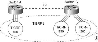
The second level is the Token Ring Bridge Relay Function (TrBRF). This is the parent VLAN to which TrCRF VLANs are assigned. At this level, the VLAN is a logical bridge and, as such, is assigned a bridge number. The logical bridge (TrBRF) contains the virtual ports that establish a connection between the TrBRF and its TrCRFs. The TrBRF can be extended across a network of switches and routers via ISL, as shown in Figure 1.
Figure 1 Physical View of Switches Interconnected via ISL
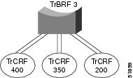
When you extend the TrBRF across an ISL link, you are essentially extending the bridge across devices, as shown in Figure 2.
Figure 2 Logical View of Switches Interconnected via ISL
Therefore, if you use source-route bridging between the TrCRFs that belong to the TrBRF, only one hop appears in the RIF.
Traffic is switched between the ports in a TrCRF and bridged via SRB or SRT between the TrCRFs in a TrBRF.
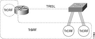
Figure 3 illustrates a TrBRF that contains TrCRFs on both a router and a switch.
Figure 3 TrCRFs in a TrBRF
TRISL Configuration Task List
To configure and monitor TRISL in your network, perform one or more of the following tasks:
•![]() Configuring IP Routing over TRISL
Configuring IP Routing over TRISL
•![]() Configuring Hot Standby Router Protocol over TRISL
Configuring Hot Standby Router Protocol over TRISL
•![]() Configuring IPX Routing over TRISL
Configuring IPX Routing over TRISL
•![]() Configuring Source-Route Bridging over TRISL
Configuring Source-Route Bridging over TRISL
•![]() Configuring Source-Route Transparent Bridging over TRISL
Configuring Source-Route Transparent Bridging over TRISL
•![]() Configuring Source-Route Translational Bridging over TRISL
Configuring Source-Route Translational Bridging over TRISL
See the "TRISL Configuration Examples" section for examples.
Configuring IP Routing over TRISL
The IP routing over TRISL VLANs feature extends IP routing capabilities to include support for routing IP frame types in VLAN configurations. To configure IP routing over TRISL, use the following commands beginning in global configuration mode:
You can configure TRISL to route source-routed traffic by enabling the collection and use of RIF information on a TRISL subinterface. This creates a "pseudoring" to terminate the RIF path on a ring. Without RIF information, a packet could not be bridged across a source-route bridged network connected to this interface.
To route source-routed traffic, use the following additional commands in interface configuration mode:
Note ![]() TRISL encapsulation must be specified for a subinterface before an IP address can be assigned to that subinterface.
TRISL encapsulation must be specified for a subinterface before an IP address can be assigned to that subinterface.
Configuring Hot Standby Router Protocol over TRISL
The Hot Standby Router Protocol (HSRP) provides fault tolerance and enhanced routing performance for IP networks. HSRP allows Cisco routers to monitor each other's operational status and very quickly assume packet forwarding responsibility in the event the current forwarding device in the HSRP group fails or is taken down for maintenance. The standby mechanism remains transparent to the attached hosts and can be deployed on any LAN type. With multiple hot-standby groups, routers can simultaneously provide redundant backup and perform load-sharing across different IP subsets.
To configure HSRP over TRISL between VLANs, use the following commands beginning in global configuration mode:
To customize hot standby group attributes, use one of the following commands in interface configuration mode, as needed:
Configuring IPX Routing over TRISL
The IPX Routing over ISL VLANs feature extends Novell NetWare routing capabilities to include support for routing all standard IPX encapsulations for Token Ring frame types in VLAN configurations. Users with Novell NetWare environments can configure either SAP or SNAP encapsulations to be routed using the TRISL encapsulation across VLAN boundaries.
Netware users can now configure consolidated VLAN routing over a single VLAN trunking interface. With configurable Token Ring encapsulation protocols on a per VLAN basis, users have the flexibility of using VLANs regardless of their NetWare Token Ring encapsulation. Encapsulation types and corresponding framing types are described in the "Configuring Novell IPX" chapter of the Cisco IOS AppleTalk and Novell IPX Configuration Guide.
Note ![]() Only one type of IPX encapsulation can be configured per VLAN (subinterface). The IPX encapsulation used must be the same within any particular subnet. A single encapsulation must be used by all NetWare systems that belong to the same LAN.
Only one type of IPX encapsulation can be configured per VLAN (subinterface). The IPX encapsulation used must be the same within any particular subnet. A single encapsulation must be used by all NetWare systems that belong to the same LAN.
To configure Cisco IOS software to route IPX on a router with connected VLANs, use the following commands beginning in global configuration mode:
Note ![]() The default IPX encapsulation format for Token Ring in Cisco IOS routers is SAP. Therefore, you only need to explicitly configure the IPX encapsulation type if your Token Ring network requires SNAP encapsulation instead of SAP.
The default IPX encapsulation format for Token Ring in Cisco IOS routers is SAP. Therefore, you only need to explicitly configure the IPX encapsulation type if your Token Ring network requires SNAP encapsulation instead of SAP.
When routing source-routed traffic for specific VLANs, use the following additional commands in interface configuration mode:
Configuring Source-Route Bridging over TRISL
To configure SRB over TRISL, use the following commands beginning in global configuration mode:
Configuring Source-Route Transparent Bridging over TRISL
To configure transparent bridging over TRISL, use the following command beginning in global configuration mode:
Configuring Source-Route Translational Bridging over TRISL
To configure source-route translational bridging over TRISL, use the following commands beginning in global configuration mode:
Note ![]() For a complete description of SR/TLB, including configuring translation compatibility with IBM 8209 bridges and configuring Token Ring LLC2 to Ethernet Type II (0x80d5) and Token Ring LLC2 to Ethernet 802.3 LLC2 (standard) translations, please refer to the "Configuring Source-Route Bridging" chapter in this publication and "Source-Route Bridging Commands" chapter in the Cisco IOS Bridging and IBM Command Reference (Volume 1 of 2).
For a complete description of SR/TLB, including configuring translation compatibility with IBM 8209 bridges and configuring Token Ring LLC2 to Ethernet Type II (0x80d5) and Token Ring LLC2 to Ethernet 802.3 LLC2 (standard) translations, please refer to the "Configuring Source-Route Bridging" chapter in this publication and "Source-Route Bridging Commands" chapter in the Cisco IOS Bridging and IBM Command Reference (Volume 1 of 2).
Configuring Automatic Spanning Tree
The automatic spanning-tree function supports automatic resolution of spanning trees in SRB networks, which provides a single path for spanning explorer frames to traverse from a given node in the network to another. Spanning explorer frames have a single-route broadcast indicator set in the routing information field. Port identifiers consist of ring numbers and bridge numbers associated with the ports. The spanning-tree algorithm for SRB does not support Topology Change Notification Bridge Protocol Data Unit (BPDU).
Although the automatic spanning-tree function can be configured with Source-Route Translational Bridging (SR/TLB), the SRB domain and transparent bridging domain have separate spanning trees. Each Token Ring interface can belong to only one spanning tree. Only one bridge group can run the automatic spanning-tree function at a time.
To create a bridge group that runs an automatic spanning-tree function compatible with the IBM SRB spanning-tree implementation, use the following command in global configuration mode:
|
|
|
|---|---|
Router(config)# bridge bridge-group protocol ibm |
Creates a bridge group that runs the automatic spanning-tree function. |
To enable the automatic spanning-tree function for a specified group of bridged interfaces in SRB or SR/TLB, use the following command in interface configuration mode:
|
|
|
|---|---|
Router(config-if)# source-bridge spanning bridge-group |
Enables the automatic spanning-tree function on a group of bridged interfaces. |
Monitoring TRISL Statistics
You can collect, clear, and display statistical information about the network.
The Duplicate Ring Protocol (DRiP) runs on Cisco routers and switches that support switched VLAN networking and is used to identify active Token Ring VLANs (TrCRFs).
DRiP maintains the status of TrCRFs and uses this information to determine whether there are multiple TrCRFs active in a TrBRF.
DRiP information is used for the following:
•![]() All-routes explorer filtering
All-routes explorer filtering
DRiP information is used in conjunction with the local configuration to determine which of the TrCRFs configured within a TrBRF have active ports. This information is used on the base switch to correctly filter all-routes explorers and on the ISL module to discard AREs that have already been on an attached ring.
•![]() Detecting the configuration of duplicate TrCRFs across routers and switches, which would cause a TrCRF to be distributed across ISL trunks
Detecting the configuration of duplicate TrCRFs across routers and switches, which would cause a TrCRF to be distributed across ISL trunks
DRiP information is used in conjunction with the local configuration information to determine which TrCRFs are already active on the switches. If a TrCRF is enabled on more than one switch or router, the ports associated with the TrCRF are disabled on all switches. A router will not disable the internal ring used for SRB and for routing source-routed traffic. Instead, the router generates the following error message to indicate that two identical TrCRFs exist:
DRIP conflict with CRF <vlan-id>
To show or clear DRiP or VLAN statistics, use one or all the following command in privileged EXEC mode:
Note ![]() When DRiP counters are cleared, the counter is reset to 0. Incrementing of DRiP counters indicates that the router is receiving packets across the TrBRF.
When DRiP counters are cleared, the counter is reset to 0. Incrementing of DRiP counters indicates that the router is receiving packets across the TrBRF.
TRISL Configuration Examples
The following sections provide TRISL configuration examples:
•![]() IP Routing Non-Source-Routed Frames Between a TRISL VLAN and a Token Ring Interface Example
IP Routing Non-Source-Routed Frames Between a TRISL VLAN and a Token Ring Interface Example
•![]() IP Routing Source-Routed Frames Between a TRISL VLAN and a Token Ring Interface Example
IP Routing Source-Routed Frames Between a TRISL VLAN and a Token Ring Interface Example
•![]() IP Routing Source-Route Frames Between a TRISL VLAN and an Ethernet ISL VLAN Example
IP Routing Source-Route Frames Between a TRISL VLAN and an Ethernet ISL VLAN Example
•![]() IP Routing Source-Routed Frames Between TRISL VLANs Example
IP Routing Source-Routed Frames Between TRISL VLANs Example
•![]() IPX Routing Non-Source-Routed Frames Between a TRISL VLAN and a Token Ring Interface Example
IPX Routing Non-Source-Routed Frames Between a TRISL VLAN and a Token Ring Interface Example
•![]() IPX Routing Source-Routed Frames Between a TRISL VLAN and a Token Ring Interface Example
IPX Routing Source-Routed Frames Between a TRISL VLAN and a Token Ring Interface Example
•![]() IPX Routing Source-Route Frames Between a TRISL VLAN and an Ethernet ISL VLAN Example
IPX Routing Source-Route Frames Between a TRISL VLAN and an Ethernet ISL VLAN Example
•![]() IPX Routing Source-Routed Frames Between TRISL VLANs Example
IPX Routing Source-Routed Frames Between TRISL VLANs Example
•![]() SRB Between Token Ring and TRISL VLAN Example
SRB Between Token Ring and TRISL VLAN Example
•![]() SRB Between TRISL VLANs Example
SRB Between TRISL VLANs Example
•![]() Transparent Bridging Between Token Ring and TRISL VLAN Example
Transparent Bridging Between Token Ring and TRISL VLAN Example
•![]() SR/TLB Between a TRISL VLAN and an Ethernet Interface Example
SR/TLB Between a TRISL VLAN and an Ethernet Interface Example
•![]() SR/TLB Between a TRISL VLAN and an Ethernet ISL VLAN Example
SR/TLB Between a TRISL VLAN and an Ethernet ISL VLAN Example
•![]() TRISL with Fast EtherChannel Example
TRISL with Fast EtherChannel Example
Note ![]() Because the VLAN Trunk Protocol (VTP) is not supported on the router configured with TRISL, the TrCRF configuration on the router must also be specified in the Catalyst 5000 switch configuration.
Because the VLAN Trunk Protocol (VTP) is not supported on the router configured with TRISL, the TrCRF configuration on the router must also be specified in the Catalyst 5000 switch configuration.
IP Routing Non-Source-Routed Frames Between a TRISL VLAN and a Token Ring Interface Example
Figure 4 illustrates IP routing between a TRISL VLAN and a Token Ring interface.
Figure 4 IP Routing Between a TRISL VLAN and a Token Ring Interface
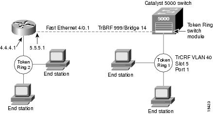
The following is the configuration for the router:
ip routing
interface TokenRing 3/1
ip address 4.4.4.1 255.255.255.0
!
interface fastethernet4/0.1
ip address 5.5.5.1 255.255.255.0
encapsulation tr-isl trbrf 999 bridge-num 14
The following is the configuration for the Catalyst 5000 switch with the Token Ring switch module in slot 5. In this configuration, the Token Ring port 1 is assigned to the TrCRF VLAN 40.
#vtp
set vtp domain trisl
set vtp mode server
set vtp v2 enable
#drip
set tokenring reduction enable
set tokenring distrib-crf disable
#vlans
set vlan 999 name trbrf type trbrf bridge 0xe stp ieee
set vlan 40 name trcrf40 type trcrf parent 999 ring 0x1 mode srt
#add token port to trcrf 40
set vlan 40 5/1
set trunk 1/2 on
IP Routing Source-Routed Frames Between a TRISL VLAN and a Token Ring Interface Example
Figure 5 illustrates IP routing source-routed frames between a TRISL VLAN and a Token Ring interface.
Figure 5 Routing Source-Routed Frames Between a TRISL VLAN and a Token Ring Interface
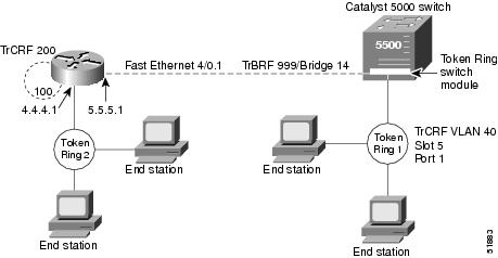
The following is the configuration for the router:
ip routing
interface TokenRing 3/1
ip address 4.4.4.1 255.255.255.0
!
interface fastethernet4/0.1
ip address 5.5.5.1 255.255.255.0
encapsulation tr-isl trbrf 999 bridge-num 14
multiring trcrf-vlan 200 ring 100
multiring all
The following is the configuration for the Catalyst 5000 switch with the Token Ring switch module in slot 5. In this configuration, the Token Ring port 5/1 is assigned to the TrCRF VLAN 40.
#vtp
set vtp domain trisl
set vtp mode server
set vtp v2 enable
#drip
set tokenring reduction enable
set tokenring distrib-crf disable
#vlans
set vlan 999 name trbrf type trbrf bridge 0xe stp ibm
set vlan 200 name trcrf200 type trcrf parent 999 ring 0x64 mode srb
set vlan 40 name trcrf40 type trcrf parent 999 ring 0x1 mode srb
#add token port to trcrf 40
set vlan 40 5/1
set trunk 1/2 on
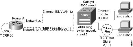
IP Routing Source-Route Frames Between a TRISL VLAN and an Ethernet ISL VLAN Example
Figure 6 illustrates IP routing source-route frames between a TRISL VLAN and an Ethernet ISL VLAN.
Figure 6 IP Routing Source-Routed Frames Between a TRISL VLAN and an Ethernet ISL VLAN
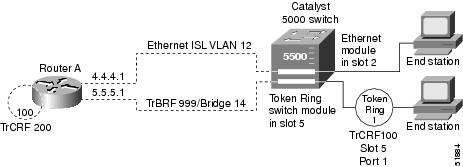
The following is the configuration for the router:
interface fastethernet4/0.1
ip address 5.5.5.1 255.255.255.0
encapsulation tr-isl trbrf-vlan 999 bridge-num 14
multiring trcrf-vlan 200 ring 100
multiring all
!
interface fastethernet4/0.2
ip address 4.4.4.1 255.255.255.0
encapsulation isl 12
The following is the configuration for the Catalyst 5000 switch with the Ethernet module in slot 2 and a Token Ring switch module in slot 5. In this configuration, the Token Ring port is assigned with TrCRF VLAN 100 and the Ethernet port is assigned with VLAN 12.
#vtp
set vtp domain trisl
set vtp mode server
set vtp v2 enable
#drip
set tokenring reduction enable
set tokenring distrib-crf disable
#vlans
set vlan 999 name trbrf type trbrf bridge 0xe stp ibm
set vlan 100 name trcrf100 type trcrf parent 999 ring 0x1 mode srb
set vlan 200 name trcrf200 type trcrf parent 999 ring 0x64 mode srb
set vlan 12 name eisl12 type ethernet
#add token port to trcrf 100
set vlan 100 5/1
#add ethernet
set vlan 12 2/1
set trunk 1/2 on
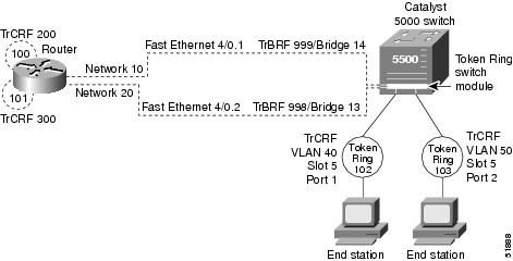
IP Routing Source-Routed Frames Between TRISL VLANs Example
Figure 7 illustrates IP routing source-routed frames between two TrBRF VLANs.
Figure 7 IP Routing Source-Routed Frames Between TrBRF VLANs
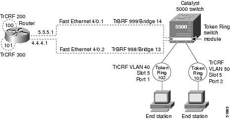
The following is the configuration for the router:
interface fastethernet4/0.1
ip address 5.5.5.1 255.255.255.0
encapsulation tr-isl trbrf-vlan 999 bridge-num 14
multiring trcrf-vlan 200 ring 100
multiring all
!
interface fastethernet4/0.2
ip address 4.4.4.1 255.255.255.0
encapsulation tr-isl trbrf-vlan 998 bridge-num 13
multiring trcrf-vlan 300 ring 101
multiring all
The following is the configuration for the Catalyst 5000 switch with the Token Ring switch module in slot 5. In this configuration, the Token Ring port attached to ring 102 is assigned with TrCRF VLAN 40 and the Token Ring port attached to ring 103 is assigned with TrCRF VLAN 50.
#vtp
set vtp domain trisl
set vtp mode server
set vtp v2 enable
#drip
set tokenring reduction enable
set tokenring distrib-crf disable
#vlans
set vlan 999 name trbrf type trbrf bridge 0xe stp ibm
set vlan 200 name trcrf200 type trcrf parent 999 ring 0x64 mode srb
set vlan 40 name trcrf40 type trcrf parent 999 ring 0x66 mode srb
set vlan 998 name trbrf type trbrf bridge 0xd stp ibm
set vlan 300 name trcrf300 type trcrf parent 998 ring 0x65 mode srb
set vlan 50 name trcrf50 type trcrf parent 998 ring 0x67 mode srb
#add token port to trcrf 40
set vlan 40 5/1
#add token port to trcrf 50
set vlan 50 5/2
set trunk 1/2 on
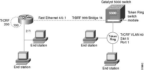
IPX Routing Non-Source-Routed Frames Between a TRISL VLAN and a Token Ring Interface Example
Figure 8 shows IPX routing non-source-routed frames between a TRISL VLAN and a Token Ring interface.
Figure 8 IPX Routing Non-Source-Routed Frames Between a TRISL VLAN and a Token Ring Interface Example
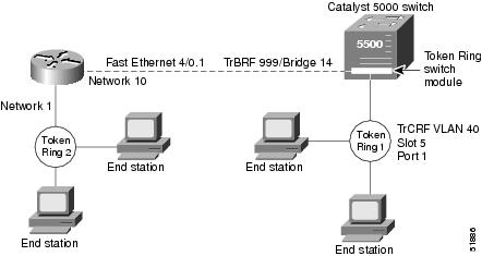
The following is the configuration for the router:
ipx routing
interface TokenRing 3/1
ipx network 1
!
interface fastethernet4/0.1
ipx network 10
encapsulation tr-isl trbrf 999 bridge-num 14
The following is the configuration for the Catalyst 5000 switch with the Token Ring switch module in slot 5. In this configuration, the Token Ring port attached to ring 1 is assigned to the TrCRF VLAN 40.
#vtp
set vtp domain trisl
set vtp mode server
set vtp v2 enable
#drip
set tokenring reduction enable
set tokenring distrib-crf disable
#vlans
set vlan 999 name trbrf type trbrf bridge 0xe stp ieee
set vlan 40 name trcrf40 type trcrf parent 999 ring 0x1 mode srt
#add token port to trcrf 40
set vlan 40 5/1
set trunk 1/2 on
IPX Routing Source-Routed Frames Between a TRISL VLAN and a Token Ring Interface Example
Figure 9 shows IPX routing source-routed frames between a TRISL VLAN and a Token Ring interface.
Figure 9 IPX Routing Source-Routed Frames Between a TRISL VLAN and a Token Ring Interface
The following is the configuration for the router:
ipx routing
!
interface TokenRing 3/1
ipx network 1
multiring all
!
interface fastethernet4/0.1
ipx network 10
encapsulation tr-isl trbrf 999 bridge-num 14
multiring trcrf-vlan 200 ring 100
multiring all
The following is the configuration for the Catalyst 5000 switch with the Token Ring switch module in slot 5. In this configuration, the Token Ring port attached to ring 1 is assigned to the TrCRF VLAN 40.
#vtp
set vtp domain trisl
set vtp mode server
set vtp v2 enable
#drip
set tokenring reduction enable
set tokenring distrib-crf disable
#vlans
set vlan 999 name trbrf type trbrf bridge 0xe stp ibm
set vlan 200 name trcrf200 type trcrf parent 999 ring 0x64 mode srb
set vlan 40 name trcrf40 type trcrf parent 999 ring 0x1 mode srb
#add token port to trcrf 40
set vlan 40 5/1
set trunk 1/2 on
IPX Routing Source-Route Frames Between a TRISL VLAN and an Ethernet ISL VLAN Example
Figure 10 shows IPX routing source-route frames between a TRISL VLAN and an Ethernet ISL VLAN.
Figure 10 IPX Routing Source-Routed Frames Between a TRISL VLAN and an Ethernet ISL VLAN
The following is the configuration for the router:
ipx routing
interface fastethernet4/0.1
ipx network 10
encapsulation tr-isl trbrf-vlan 999 bridge-num 14
multiring trcrf-vlan 20 ring 100
multiring all
!
interface fastethernet4/0.2
ipx network 30
encapsulation isl 12
The following is the configuration for the Catalyst 5000 switch with the Ethernet module in slot 2 and a Token Ring switch module in slot 5. In this configuration, the Token Ring port is assigned with TrCRF VLAN 100 and the Ethernet port is assigned with VLAN 12.
#vtp
set vtp domain trisl
set vtp mode server
set vtp v2 enable
#drip
set tokenring reduction enable
set tokenring distrib-crf disable
#vlans
set vlan 999 name trbrf type trbrf bridge 0xe stp ibm
set vlan 100 name trcrf100 type trcrf parent 999 ring 0x1 mode srb
set vlan 20 name trcrf20 type trcrf parent 999 ring 0x64 mode srb
set vlan 12 name default type eisl12
#add token port to trcrf 100
set vlan 100 5/1
#add ethernet
set vlan 12 2/1
set trunk 1/2 on
IPX Routing Source-Routed Frames Between TRISL VLANs Example
Figure 11 shows IPX source-routed frames between TRISL VLANs.
Figure 11 IPX Routing Source-Routed Frames Between TRISL VLANs
The following is the configuration for the router:
ipx routing
interface fastethernet4/0.1
ipx network 10
encapsulation tr-isl trbrf-vlan 999 bridge-num 14
multiring trcrf-vlan 200 ring 100
multiring all
!
interface fastethernet4/0.2
ipx network 20
encapsulation tr-isl trbrf-vlan 998 bridge-num 13
multiring trcrf-vlan 300 ring 101
multiring all
The following is the configuration for the Catalyst 5000 switch with the Token Ring switch module in slot 5. In this configuration, the Token Ring port attached to ring 102 is assigned with TrCRF VLAN 40 and the Token Ring port attached to ring 103 is assigned with TrCRF VLAN 50.
#vtp
set vtp domain trisl
set vtp mode server
set vtp v2 enable
#drip
set tokenring reduction enable
set tokenring distrib-crf disable
#vlans
set vlan 999 name trbrf type trbrf bridge 0xe stp ibm
set vlan 200 name trcrf200 type trcrf parent 999 ring 0x64 mode srb
set vlan 40 name trcrf40 type trcrf parent 999 ring 0x66 mode srb
set vlan 998 name trbrf type trbrf bridge 0xd stp ibm
set vlan 300 name trcrf300 type trcrf parent 998 ring 0x65 mode srb
set vlan 50 name trcrf50 type trcrf parent 998 ring 0x67 mode srb
#add token port to trcrf 40
set vlan 40 5/1
#add token port to trcrf 50
set vlan 50 5/2
set trunk 1/2 on
SRB Between Token Ring and TRISL VLAN Example
Figure 12 illustrates SRB between a Token Ring interface on a router and a TRISL VLAN.
Figure 12 SRB Between a Token Ring Interface and TRISL VLAN
The following is the configuration for the router with the Token Ring interface:
source-bridge ring-group 100
!
interface TokenRing3/1
ring speed 16
source-bridge 10 1 100
source-bridge spanning
!
interface fastethernet4/0.1
encapsulation tr-isl trbrf-vlan 999 bridge-num 14
source-bridge trcrf-vlan 40 ring-group 100
source-bridge spanning
!
The following is the configuration for the Catalyst 5000 switch:
#vtp
set vtp domain trisl
set vtp mode server
set vtp v2 enable
#drip
set tokenring reduction enable
set tokenring distrib-crf disable
#vlans
set vlan 999 name trbrf type trbrf bridge 0xe stp ibm
set vlan 40 name trcrf40 type trcrf parent 999 ring 0x64 mode srb
set vlan 50 name trcrf50 type trcrf parent 999 ring 0x14 mode srb
#add token port to trcrf 50
set vlan 50 5/1
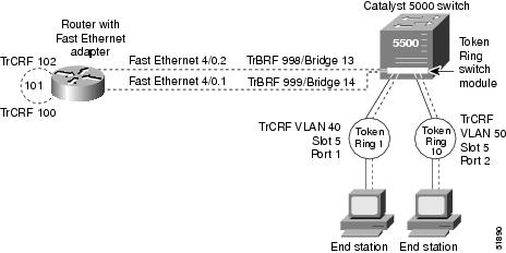
SRB Between TRISL VLANs Example
Figure 13 illustrates SRB between two TrCRF VLANs.
Figure 13 SRB Between TRISL VLANs
The following is the configuration for the router:
source-bridge ring-group 101
!
interface fastethernet4/0.1
encapsulation tr-isl trbrf 999 bridge-num 14
source-bridge trcrf-vlan 100 ring-group 101
source-bridge spanning
!
interface fastethernet4/0.2
encapsulation tr-isl trbrf 998 bridge-num 13
source-bridge trcrf-vlan 102 ring-group 101
source-bridge spanning
The following is the configuration for the Catalyst 5000 switch with the Token Ring switch module in slot 5. The Token Ring port on 5/1 is assigned to TrCRF VLAN 40 and the Token Ring port on 5/2 is assigned to TrCRF VLAN 50.
In this configuration, the keyword name is optional and srb is the default mode.
#vtp
set vtp domain trisl
set vtp mode server
set vtp v2 enable
#drip
set tokenring reduction enable
set tokenring distrib-crf disable
#vlans
set vlan 999 name trbrf type trbrf bridge 0xe stp ibm
set vlan 100 name trcrf100 type trcrf parent 999 ring 0x65 mode srb
set vlan 40 name trcrf40 type trcrf parent 999 ring 0x1 mode srb
set vlan 998 name trbrf type trbrf bridge 0xd stp ibm
set vlan 102 name trcrf102 type trcrf parent 998 ring 0x65 mode srb
set vlan 50 name trcrf50 type trcrf parent 998 ring 0xa mode srb
#add token port to trcrf 40
set vlan 40 5/1
#add token port to trcrf 50
set vlan 50 5/2
#enable trunk
set trunk 1/2 on
Transparent Bridging Between Token Ring and TRISL VLAN Example
Figure 14 illustrates transparent bridging between a router's Token Ring interface and a TRISL VLAN.
Figure 14 Transparent Bridging Between Token Ring and TRISL VLAN
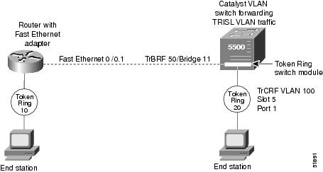
The following is the configuration for the router:
bridge 1 protocol ieee
!
interface Tokenring0
 bridge-group 1
!
interface fastethernet0/0.1
 encapsulation tr-isl trbrf-vlan 50 bridge-num 11
 bridge-group 1
The following is the configuration for the Catalyst 5000 switch with a Token Ring switch module in
slot 5:
#vtp
set vtp domain trisl
set vtp mode server
set vtp v2 enable
#drip
set tokenring reduction enable
set tokenring distrib-crf disable
#vlans
set vlan 50 name trbrf50 type trbrf bridge 0xb stp ieee
set vlan 100 name trcrf100 type trcrf ring 0x14 parent 50 mode srt
#enable trunk
set trunk 1/2 on
#add token port to trcrf 100
set vlan 100 5/1
SR/TLB Between a TRISL VLAN and an Ethernet Interface Example
Figure 15 illustrates SR/TLB between a TRISL VLAN and an Ethernet interface.
Figure 15 SR/TLB Between a TRISL VLAN and an Ethernet Interface
The following is the configuration for the router:
source-bridge ring-group 100
source-bridge transparent 100 101 6 1
!
interface Ethernet2/0
bridge-group 1
!
interface fastethernet4/0.1
encapsulation tr-isl trbrf-vlan 999 bridge-num 14
source-bridge trcrf-vlan 200 ring-group 100
source-bridge spanning
!
bridge 1 protocol ieee
!
The following is the configuration for the Catalyst 5000 switch with an Ethernet card in module 5 and using port 1. The Token Ring port on 5/1 is assigned to TrCRF VLAN 40.
#vtp
set vtp domain trisl
set vtp mode server
set vtp v2 enable
#drip
set tokenring reduction enable
set tokenring distrib-crf disable
#vlans
set vlan 999 name trbrf999 type trbrf bridge 0xe stp ibm
set vlan 200 name trcrf200 type trcrf parent 999 ring 0x64 mode srb
set vlan 40 name trcrf40 type trcrf parent 999 ring 0x1 mode srb
#add token port to trcrf 40
set vlan 40 5/1
#enable trunk
set trunk 1/2 on
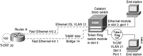
SR/TLB Between a TRISL VLAN and an Ethernet ISL VLAN Example
Figure 16 illustrates SR/TLB between a TRISL VLAN and an Ethernet ISL VLAN.
Figure 16 SR/TLB Between a TRISL VLAN and an Ethernet ISL VLAN
The following is the configuration for the router:
source-bridge ring-group 100
source-bridge transparent 100 101 6 1
!
interface fastethernet4/0.1
encapsulation tr-isl trbrf-vlan 999 bridge-num 14
source-bridge trcrf-vlan 20 ring-group 100
source-bridge spanning
!
interface fastethernet4/0.2
encapsulation isl 12
bridge-group 1
!
bridge 1 protocol ieee
The following is the configuration for the Catalyst 5000 switch with an Ethernet module in slot 2 and a Token Ring switch module in slot 5. In this configuration, the Token Ring port attached to ring 101 is assigned to TrCRF VLAN 21, and the router's virtual ring is assigned to TrCRF VLAN 20.
#vtp
set vtp domain trisl
set vtp mode server
set vtp v2 enable
#drip
set tokenring reduction enable
set tokenring distrib-crf disable
#vlans
set vlan 999 type trbrf bridge 0xe stp ibm
set vlan 20 type trcrf parent 999 ring 0x64 mode srb
set vlan 21 type trcrf parent 999 ring 0x65 mode srb
#add token port to trcrf 21
set vlan 21 5/1
#add ethernet
set vlan 12 type ethernet
set vlan 12 2/1
set trunk 1/2 on
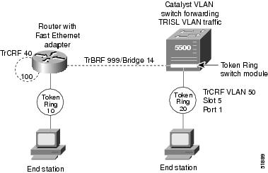
TRISL with Fast EtherChannel Example
Figure 17 illustrates TRISL with Fast EtherChannel.
Figure 17 Sample Configuration of TRISL with Fast EtherChannel

The following is the configuration for the Cisco 7500:
source-bridge ring-group 50
interface Port-channel1
no ip address
no ip directed-broadcast
no ip route-cache distributed
hold-queue 300 in
interface Port-channel1.1
encapsulation tr-isl trbrf-vlan 20 bridge-num 1
ip address 10.131.25.1 255.255.255.0
no ip redirects
no ip directed-broadcast
source-bridge trcrf-vlan 23 ring-group 50
source-bridge spanning
interface Port-channel1.2
encapsulation tr-isl trbrf-vlan 30 bridge-num 2
ip address 10.131.24.1 255.255.255.0
no ip redirects
no ip directed-broadcast
source-bridge trcrf-vlan 33 ring-group 50
source-bridge spanning
interface fastethernet4/1/0
no ip address
no ip directed-broadcast
no ip route-cache distributed
channel-group 1
interface fastethernet4/1/1
no ip address
no ip directed-broadcast
no ip route-cache distributed
channel-group 1
The following is the configuration for the Catalyst 5000 Switch:
set vlan 10 name VLAN0010 type ethernet mtu 1500 said 100010 state active
 set vlan 20 name VLAN0020 type trbrf mtu 4472 said 100020 state active bridge 0x1 stp
ieee
 set vlan 30 name VLAN0030 type trbrf mtu 4472 said 100030 state active bridge 0x2 stp
ieee
 set vlan 22 name VLAN0022 type trcrf mtu 4472 said 100022 state active parent 20 ring 0x1
mode srt aremaxhop 7 stemaxhop 7
 set vlan 23 name VLAN0023 type trcrf mtu 4472 said 100023 state active parent 20 ring
0x32 mode srt aremaxhop 7 stemaxhop 7
 set vlan 32 name VLAN0032 type trcrf mtu 4472 said 100032 state active parent 30 ring 0x2
mode srt aremaxhop 7 stemaxhop 7
 set vlan 33 name VLAN0033 type trcrf mtu 4472 said 100033 state active parent 30 ring
0x32 mode srt aremaxhop 7 stemaxhop 7
set port channel 1/1-2 on
set trunk 1/1 on isl 1-1005
set trunk 1/2 on isl 1-1005
add token port to crf 22
set vlan 22 5/1
add token port to crf 32
set vlan 32 5/2
TRISL with Fast EtherChannel only runs on the Cisco 7500. The MTU size can be set to more than 1500 if all the members of the port channel interface are 2FE/ISL adaptors. If, on the other hand, any member of the port channel interface is a non 2FE/ISL adaptor, then the MTU size is not configurable and defaults to 1500 bytes. Also, only IP utilizes all four links. Spanning Tree Protocol must be disabled if transparent bridging is configured on the FEC. The port-channel interface is the routed interface. Do not enable Layer 3 addresses on the physical Fast Ethernet interfaces. Do not assign bridge groups on the physical Fast Ethernet interfaces because it creates loops. Also, you must disable Spanning Tree Protocol if transparent bridging is configured on the FEC.
 Feedback