Cisco BWG Release 2.2 Feature Guide for Cisco IOS Release 12.4(24)YG2
Bias-Free Language
The documentation set for this product strives to use bias-free language. For the purposes of this documentation set, bias-free is defined as language that does not imply discrimination based on age, disability, gender, racial identity, ethnic identity, sexual orientation, socioeconomic status, and intersectionality. Exceptions may be present in the documentation due to language that is hardcoded in the user interfaces of the product software, language used based on RFP documentation, or language that is used by a referenced third-party product. Learn more about how Cisco is using Inclusive Language.
- Updated:
- January 17, 2011
Chapter: Configuring the Cisco Broadband Wireless Gateway
- Service Flows
- Multiple Service Flow Creation
- Configuring BWG Service
- Sample Configuration
- Verifying the Configuration
- Mapping of Service Flows to DiffServ Classes
- Configuring Service Flows on the BWG
- Configuration Example
- Configuring Service Flow Packet Classification
- Configuration Example
- Critical Service Flow
- Delay the Attachment Response from BWG
- BWG Session Redundancy and High Availability Infrastructure
- Subscriber Management
- DHCP and AAA
- Dynamic Synchronization
- Configuring Session Redundancy
- Configuration Example
- Authentication
- Accounting
- Subscriber IP Address
- QoS
- Statistics and Counters
- BWG Load Balancing
- Data Path and GRE
- Version Control
- Limitations
- Switchover
Configuring the Cisco Broadband Wireless Gateway
This feature module explains and discusses the feature set for the Cisco Broadband Wireless Gateway (BWG). Additionally, this feature module explains how to configure those features and provides sample configurations when appropriate.
This chapter contains information on the following features:
•![]() Ethernet Convergence Sublayer (CS)
Ethernet Convergence Sublayer (CS)
–![]() Ethernet CS—Data and Control Both on R6
Ethernet CS—Data and Control Both on R6
•![]() WiMAX NWG Specification (1.2.2) Compliant
WiMAX NWG Specification (1.2.2) Compliant
–![]() AAA Access for Unauthenticated Subscriber
AAA Access for Unauthenticated Subscriber
•![]() Support for MS/Host with Statically Assigned IP
Support for MS/Host with Statically Assigned IP
–![]() Network Admission of an Authenticated User
Network Admission of an Authenticated User
–![]() Support of Un-Authenticated User
Support of Un-Authenticated User
•![]() IP Address Allocation Using DHCP
IP Address Allocation Using DHCP
–![]() Configuring IP Address Allocation
Configuring IP Address Allocation
–![]() Support of Multiple Hosts Behind a SS
Support of Multiple Hosts Behind a SS
•![]() Service Flow Creation and Management
Service Flow Creation and Management
–![]() Multiple Service Flow Creation
Multiple Service Flow Creation
–![]() Mapping of Service Flows to DiffServ Classes
Mapping of Service Flows to DiffServ Classes
–![]() Configuring Service Flows on the BWG
Configuring Service Flows on the BWG
–![]() Configuring Service Flow Packet Classification
Configuring Service Flow Packet Classification
–![]() Delay the Attachment Response from BWG
Delay the Attachment Response from BWG
•![]() AAA Accounting Start-Stop-Interim
AAA Accounting Start-Stop-Interim
–![]() Configuring Profile-based Hot-lining
Configuring Profile-based Hot-lining
•![]() AAA Packet of Disconnect Message (PoD)
AAA Packet of Disconnect Message (PoD)
•![]() AAA-based Static IP Address Provisioning
AAA-based Static IP Address Provisioning
•![]() Keepalive Support for R6 Interface
Keepalive Support for R6 Interface
–![]() BWG Session Redundancy and High Availability Infrastructure
BWG Session Redundancy and High Availability Infrastructure
–![]() Configuring Session Redundancy
Configuring Session Redundancy
–![]() QoS
QoS
–![]() Configuring Cisco IOS SLB for Load Balancing
Configuring Cisco IOS SLB for Load Balancing
–![]() Configuring the BWG for Load Balancing
Configuring the BWG for Load Balancing
–![]() PMIP Authenticated Network Identifier (PANI), page 3-4
PMIP Authenticated Network Identifier (PANI), page 3-4
–![]() Configuring DNS and Default Gateway, page 3-6
Configuring DNS and Default Gateway, page 3-6
New Features in Release 2.2
The following features are added as part of Release 2.2. They are also cross-referenced in the main features list.
•![]() L2-L2 Bridging
L2-L2 Bridging
•![]() Interim accounting update during handoff
Interim accounting update during handoff
•![]() PMIP Authenticated Network Identifier (PANI) as the Network Access Identifier (NAI)
PMIP Authenticated Network Identifier (PANI) as the Network Access Identifier (NAI)
•![]() PMIP DHCP proxy support for sending DNS and Default Gateway configuration from local configuration or from AAA server.
PMIP DHCP proxy support for sending DNS and Default Gateway configuration from local configuration or from AAA server.
New Features in Release 2.0
The following features were added as part of Release 2.0. They are also cross-referenced in the main features list.
•![]() Support for Proxy Mobile IP
Support for Proxy Mobile IP
•![]() WiMAX NWG Specification (1.2.2) Compliant
WiMAX NWG Specification (1.2.2) Compliant
•![]() AAA Packet of Disconnect Message (PoD)
AAA Packet of Disconnect Message (PoD)
•![]() AAA-based Static IP Address Provisioning
AAA-based Static IP Address Provisioning
Ethernet Convergence Sublayer (CS)
The Wimax Ethernet Convergence Sublayer (CS) allows a WiMAX network to provide Ethernet Service directly to customers. In comparison with the IP CS, it allows IEEE 802.3 frames (carrying higher layer IP datagrams) to be encapsulated in the 802.16 PDUs. In the Cisco BWG 1.1 release, only two options of Ethernet CS are implemented: BS local switch (enterprise customers), and L2-L3 bridging conversion (residential customers).
As a part of Ethernet CS requirement, the BWG will support statically assigned IP addresses for the CPE/MS/host. This includes the following sub-features for the BWG:
•![]() Enforce a maximum number (8) of active hosts per subscriber/CPE
Enforce a maximum number (8) of active hosts per subscriber/CPE
•![]() Auto-learning of L2/L3 details of the hosts through ARP, or any uplink packet from the host.
Auto-learning of L2/L3 details of the hosts through ARP, or any uplink packet from the host.
•![]() Static host IP verification with Framed-Route from AAA
Static host IP verification with Framed-Route from AAA
•![]() A mechanism to age/bump out the idle host.
A mechanism to age/bump out the idle host.
Ethernet Convergence Sublayer (CS)—R6 Control Only
In the Cisco 12.4(15)XL1 release, the WiMAX R6 interface between the BWG and Base Station (BS) is used for signaling only; the BWG instructs the BS to switch traffic locally. In the absence of GRE encapsulation, the BWG does not receive the bearer traffic from the BS. Instead, the BS must switch or forward the ethernet frames to an externally connected L2 Switch.

Note ![]() The R6 Control Plane Only feature should only be used for the Ethernet CS in the Cisco BWG R1.1 release.
The R6 Control Plane Only feature should only be used for the Ethernet CS in the Cisco BWG R1.1 release.
Since the data packets no longer go through the BWG in this configuration, the BWG needs the following adjustments:
•![]() Session Idle Timer: The BWG needs to ensure that a session remains open even if no packet is received or sent for the subscriber.
Session Idle Timer: The BWG needs to ensure that a session remains open even if no packet is received or sent for the subscriber.
•![]() When AAA sets the session timer to 0, it indicates it is infinite.
When AAA sets the session timer to 0, it indicates it is infinite.
•![]() Accounting: The BWG only performs "Accounting Start" and "Accounting Stop", which corresponds to the service flow creation and deletion. Interim periodic accounting updates are not performed since BWG does not receive bearer traffic in this scenario.
Accounting: The BWG only performs "Accounting Start" and "Accounting Stop", which corresponds to the service flow creation and deletion. Interim periodic accounting updates are not performed since BWG does not receive bearer traffic in this scenario.
In cases where the BWG does not receive the de-registration request from BS, the absolute session timer is used to de-register the MS on the BWG in order to remove hanging sessions.
The following steps illustrate the sequence of events for the R6 Control Only feature:
Step 1 ![]() SS sends a registration message to the BS. The BS forwards it to the BWG.
SS sends a registration message to the BS. The BS forwards it to the BWG.
Step 2 ![]() The BWG asks for profile from the AAA server with user_name MSID@proxy-realm. Proxy-realm is configured in the user-group.
The BWG asks for profile from the AAA server with user_name MSID@proxy-realm. Proxy-realm is configured in the user-group.
Step 3 ![]() AAA sends the SLA profile back with the following information:
AAA sends the SLA profile back with the following information:
–![]() SS is identified as a business based on the SLA profile (which is configured as encap-type none on the BWG); in this case the traffic that is locally switched at the BS identifies this as an Enterprise.
SS is identified as a business based on the SLA profile (which is configured as encap-type none on the BWG); in this case the traffic that is locally switched at the BS identifies this as an Enterprise.
–![]() The VLAN ID (unique for every business SS connected to same BS). For example, the VLAN ID = 250.
The VLAN ID (unique for every business SS connected to same BS). For example, the VLAN ID = 250.
Step 4 ![]() The BWG sends the Service Flow profiles info to the BS, along with VLAN ID and the Packet Classifications rules. The BS further sends the uplink Packet Classification rules to the SS.
The BWG sends the Service Flow profiles info to the BS, along with VLAN ID and the Packet Classifications rules. The BS further sends the uplink Packet Classification rules to the SS.
Step 5 ![]() Upstream traffic is initiated: this assumes that the CPE router will send uplink .1q tagged traffic, with following VLANs:
Upstream traffic is initiated: this assumes that the CPE router will send uplink .1q tagged traffic, with following VLANs:
–![]() VLAN 10 (Sales)
VLAN 10 (Sales)
–![]() VLAN 20 (Voice)
VLAN 20 (Voice)
Step 6 ![]() If the PCR is such that the SS will put traffic from VLAN 10 into Service Flow 1, this service flow type is BE. If the PCR is such that the SS will put traffic from VLAN 20 into Service Flow 2, this service flow type is UGS. The SS sends traffic to the BS.
If the PCR is such that the SS will put traffic from VLAN 10 into Service Flow 1, this service flow type is BE. If the PCR is such that the SS will put traffic from VLAN 20 into Service Flow 2, this service flow type is UGS. The SS sends traffic to the BS.
Step 7 ![]() The BS assigns another .1q tag on incoming traffic for enterprise x (for example VLAN ID = 250). The inner tag is left unchanged. Traffic is switched to the L2 network, and does not go to the BWG.
The BS assigns another .1q tag on incoming traffic for enterprise x (for example VLAN ID = 250). The inner tag is left unchanged. Traffic is switched to the L2 network, and does not go to the BWG.
Step 8 ![]() For downstream traffic, the following occurs:
For downstream traffic, the following occurs:
–![]() The BS receives traffic from the L2 switched network.
The BS receives traffic from the L2 switched network.
–![]() Enterprise traffic does not come through BWG.
Enterprise traffic does not come through BWG.
–![]() The PCR will tell the BS on what SF traffic has to be sent.
The PCR will tell the BS on what SF traffic has to be sent.
–![]() The BS strips the entire outer tag and forwards the remaining packet traffic over the air by SF1 (BE) or SF2 (UGS).
The BS strips the entire outer tag and forwards the remaining packet traffic over the air by SF1 (BE) or SF2 (UGS).
Step 9 ![]() The SS receives the traffic and forwards it to the switch. The inner tag is left unchanged.
The SS receives the traffic and forwards it to the switch. The inner tag is left unchanged.
Additionally, in this scenario the BS, rather than the BWG, terminates the uplink/downlink service flows. The BWG sends the downlink classifiers to the BS so that the BS can choose a proper downlink service flow for a packet. The BS needs the downlink classifiers to select the 802.16e air link connection ID/service flow. The BWG also signals the BS which VLAN tag to use for uplink traffic.
While the BWG design allows the flexibility to perform BS local switching on a flow-by-flow basis, for Release 1.1 all service flows should be configured to be either collectively BS-local switched, or BWG switched for a particular subscriber.
Configuring R6 Control Only
This section provides information on how to configure the R6 Control Only feature on the Cisco BWG. To enable R6 Control Only, perform the following tasks:
Note ![]() For BWG Release 1.1, the same vlan should be configured in the same SLA profile.
For BWG Release 1.1, the same vlan should be configured in the same SLA profile.
Note ![]() When the vlan is downloaded from AAA, it will overwrite the vlans locally configured for all service flows.
When the vlan is downloaded from AAA, it will overwrite the vlans locally configured for all service flows.
The BWG controls the BS's local switching through Data Path Encapsulation Type (NONE) and Data Path ID (Priority + VLAN ID) in the R6 DP Registration Request message. Note that the VLAN ID defined here could be overwritten from AAA. The VLAN Priority (the 3 most significant bits in VLAN tag) comes from DSCP/Precedence defined for the service flow. If DSCP/Precedence is not locally defined, it is calculated based on WiMAX QoS Data Delivery Service Type used for the service flow.
Ethernet CS—Data and Control Both on R6
To align with the WiMAX Forum NWG standard, Cisco's R6 interface supports Ethernet CS with data and control. As noted earlier, only the L2-L3 bridging option for the BWG is supported in this release.
The L2 uplink traffic comes from the host behind the CPE/MS, and these packets are encapsulated 802.16 PDUs and sent to the BS by the CPE through the R1 interface. The BS then encapsulates the Ethernet frame into the GRE packet (the GRE tunnel was established during R6 signaling exchange), and sends it to the BWG. The BWG receives the GRE packet through the R6 data path. After stripping the GRE header and L2 header, the inner IP packet is forwarded to a proper interface configured in the intended VRF.
When the BWG receives the downlink packets, it finds the related host where the L2 information related to the particular host is saved. The L2 information, along with the L3 information carried in the packet, is used to compare with the configured classifiers. As a result, a proper service flow is selected. Once a service flow is selected, the saved L2 information for the host is used to encapsulate the received IP packets.
The host's L2/L3 information is dynamically learned by the BWG through the following mechanisms:
•![]() DHCP procedure from host
DHCP procedure from host
•![]() ARP Request from host
ARP Request from host
•![]() Any uplink packet from host
Any uplink packet from host
VLAN to VRF Mapping for L2-L3 Bridging
This feature allows that the uplink L2 traffic with a particular VLAN ID is mapped to a VRF routing domain to forward the IP packets. On the other hand, the downlink IP traffic from a particular VRF will be sent to the MS encapsulated with the same VLAN ID. Note that BWG is designed to support at most one VLAN ID for each host behind MS.
Packet Fragmentation Handling
The virtual template interface on the BWG must be configured with a MTU so that no GRE fragmentation is needed for the R6 data path. The preferable MTU value is less than 1440.
For downlink packets larger than the MTU configured for the virtual template interface, they will be fragmented by IOS, and in doing so, IOS expects to clear the DF bits in the original packets. The BWG receives two IP packets in this scenario. The two IP packets are GRE encapsulated separately, and sent to the BS. The BS transparently passes the two packets to the host where they are assembled and delivered to an application.
For a large uplink packet, the BS clears the DF bits, fragments it into two packets, and sends them to the BWG. The BWG does not reassemble the packets, but forwards them separately.
Support for Jumbo Frames
This feature allows the BWG to support jumbo frames of up to 2000 bytes in payload. Previously, 1500 bytes was the limit beyond which packets are fragmented. The feature raises the Maximum Transfer Unit (MTU) to 2000.
•![]() The mtu has been set for the BWG application to 2000. Configuration in the virtual-template interface allows the change in configuration for mtu, but what is reflected in the virtual-access interfaces is 2000 for BWG.
The mtu has been set for the BWG application to 2000. Configuration in the virtual-template interface allows the change in configuration for mtu, but what is reflected in the virtual-access interfaces is 2000 for BWG.
•![]() The default mtu and ip mtu are respectively 2000 and 1500 in the Virtual-Template interface. So if neither are configured at BWG boot time, the configuration for the virtual-template interface in the running-config will look like the following:
The default mtu and ip mtu are respectively 2000 and 1500 in the Virtual-Template interface. So if neither are configured at BWG boot time, the configuration for the virtual-template interface in the running-config will look like the following:
Router#sh run | sec Virt
interface Virtual-Template1
mtu 2000
ip address 3.3.3.3 255.255.255.0
ip mtu 1500
encapsulation agw
•![]() Once mtu is configured, ip mtu can be configured to any value less or equal to the mtu and will be reflected dynamically in the virtual-access interface.
Once mtu is configured, ip mtu can be configured to any value less or equal to the mtu and will be reflected dynamically in the virtual-access interface.
A no ip mtu will set ip mtu in the virtual-access interface to mtu (2000). Any other desired value for ip mtu has to be explicitly configured in the virtual-template interface.
DHCP Option 82 Enhancement
In order to allow the BWG to build the L2 header for downlink DHCP packets, the entire L2 header is coded in the Option 82, which is reflected back from the DHCP server. This sub-option only applies between the BWG and DHCP server.
DSCP Calculation/Marking/Signaling
For downlink traffic, the DSCP marking is performed by the BWG. The outer IP DSCP value is obtained in the order of precedence from:
•![]() DSCP/Precedence set for the flow.
DSCP/Precedence set for the flow.
•![]() Calculated from SF's Data Delivery Service Type as shown in the following table.
Calculated from SF's Data Delivery Service Type as shown in the following table.
|
|
|
UGS |
46 |
ERT-VR |
38 |
RT-VR |
30 |
NRT-VR |
22 |
BE |
0 |
Note ![]() The inner IP's DSCP value is no longer used for marking the outer IP's DSCP.
The inner IP's DSCP value is no longer used for marking the outer IP's DSCP.
Note ![]() The inner IP value is also marked.
The inner IP value is also marked.
Note ![]() The SF QoS to DSCP mapping table is used only when the DSCP is not configured for the SF.
The SF QoS to DSCP mapping table is used only when the DSCP is not configured for the SF.
For uplink traffic, the BWG obtains the DSCP value in the same way as for the downlink service flow. The uplink DSCP value is signaled to the BS in the Data Path Info TLV.
Consider that DSCP marking of inner user (uplink) packets cannot be trusted; therefore, the same uplink DSCP value signaled to BS for a service flow is also used to re-mark the R3 uplink packets.
DSCP Marking
In Release 2.0, the BWG supports marking of outer IP DSCP value for downlink data traffic in the following two ways:
•![]() Using DSCP value specified in downlink service-flow profile
Using DSCP value specified in downlink service-flow profile
router(config-gw-sf-dir)#set dscp value
•![]() Using DSCP value from inbound R3 IP packet
Using DSCP value from inbound R3 IP packet
router(config-gw-sf-dir)#set dscp r3
The BWG supports the marking of R3 IP DSCP value for uplink data traffic in the following three ways:
•![]() Using inner IP DSCP value (default)
Using inner IP DSCP value (default)
•![]() Using outer R6 IP DSCP value
Using outer R6 IP DSCP value
router(config-gw-sf-dir)#set r3 dscp r6-outer
•![]() Using DSCP value specified in uplink service-flow profile
Using DSCP value specified in uplink service-flow profile
router(config-gw-sf-dir)#set r3 dscp value
Ethernet Frame Support
The BWG can support Ethernet II, LLC (802.2) and Ethernet SNAP frame types for different hosts. However, one particular host must use the same frame type during its session. In other words, one particular host can only transmit packets with the same Ethernet frame type.
Ethernet VLAN Support
Ethernet packets with a VLAN tag (specifically 802.1Q and Q-in-Q) are also supported.
Ethernet FCS (CRC)
There should be no CRC for both uplink and downlink packets over GRE towards the BWG.
Limitations
The following CS Ethernet limitations exist in Cisco BWG release 1.1 and above:
•![]() Layer 2 broadcast/multicast packets from the MS other than ARP and DHCP are dropped at the BWG.
Layer 2 broadcast/multicast packets from the MS other than ARP and DHCP are dropped at the BWG.
WiMAX NWG Specification (1.2.2) Compliant
The BWG supports both the Cisco R6 and NWG specification at the same time. No configuration is needed for this feature. The BWG distinguishes Cisco R6 from NWG R6 with the message header "Version" field. This distinction is per-subscriber-based in the BWG. When the first WiMAX R6 message for a session Version = 1, it is designated as NWG R6. Similarly if the first message carries a Version = 0x81, it is Cisco R6. A session must use the same flavor of R6 throughout its session life span except for a handover.
Handover from two BSs with different flavors of R6 is also supported.
L2-L2 Bridging
From Release 2.2, BWG supports L2-L2 Bridging. To configure L2-L2 bridging on BWG, you should be familiar with the integrated routing and bridging (IRB) feature of IOS.
Compared with L2-L3 bridging, L2-L2 bridging allows BWG to pass through the Ethernet CS packets intact.
L2-L2 bridging is enabled separately for each user-group. If the L2-L2 feature is enabled for a user-group, the L2-L3 feature is automatically disabled for that user-group.
To enable bridging on a Wimax user group, the group needs to be first added to a bridge group. When a user-group is added to a bridge-group, a virtual Wimax interface (Wimax<bridge-group>) is created. This virtual Wimax interface represents the user-group in the bridge-group. You cannot add multiple user groups to the same bridge group.
Use the bridge-group command to create bridge groups.
The following is a n example of how to configure a bridge group:
bridge irb
!
interface Ethernet1/1
description Interface belong to bridge-group 1
bridge-group 2
no bridge-group 2 source-learning
no ip address
!
bridge 2 protocol ieee
!
wimax agw user group-list wimax
user-group any
aaa authentication method-list agw
aaa accounting method-list agw
sla profile-name silver
bridge-group 2
no bridge-group 2 source-learning
bridge-group 2 transparent-vlan vlan-tag
Ethernet IP Host
For Ethernet IP hosts, a BWG host entry is created based on the pass-through ARP packets, or any other uplink data packets. The host's IP address is captured in the subscriber's host entry table in the BWG.
ARP packets sent to the MS or host are replied to by the BWG (proxy ARP). Packets other than ARP packets —such as downlink broadcast or multicast L2 packets — sent to the Wimax gets dropped.
BWG acts as a layer 2 DHCP relay agent for any DHCP requests generated by the host. BWG adds DHCP option 82 containing circuit-id and remote-id to any upstream DHCP packet. But in the case of bridging, BWG does not have layer 3 network identification and therefore does not set the giaddr field.
PPPoE Host
For a PPPoE host, the BWG intercepts its PPPoE Discovery (signaling) packets. The following is a list of packets that are intercepted:
•![]() PPPoE Active Discovery Initiation (PADI)
PPPoE Active Discovery Initiation (PADI)
•![]() PPPoE Active Discovery Offer (PADO)
PPPoE Active Discovery Offer (PADO)
•![]() PPPoE Active Discovery Request (PADR)
PPPoE Active Discovery Request (PADR)
•![]() PPPoE Active Discovery Session-confirmation (PADS)
PPPoE Active Discovery Session-confirmation (PADS)
•![]() PPPoE Active Discovery Terminate (PADT)
PPPoE Active Discovery Terminate (PADT)
A BWG host entry corresponding to PADS is created only after BWG detects the PADS sent from the network to the client.
You can create a maximum of 20 PPP0E hosts for each subscriber. A new host is only accepted if at least one of the existing host's idle period has exceeded a threshold value. The host that has been idle for the longest period is replaced with a new host. The host idle threshold is 75% of the session idle timer.
BWG also adds a Vendor-specific tag and Relay Session ID tag to every PADI and PADR packets. Vendor-specific tags includes the circuit ID (SF ID) and Remote ID (MSID) sub options. Relay session ID tag is used to insert SFID. BWG removes these tags from the PADO and PADS packets before forwarding them to the PPPoE client.
Transparent VLAN
With L2-L2 Bridging, BWG allows you to configure the L2VPN.
To enable the L2VPN features for enterprises, BWG disables ARP, DHCP and PPPoE intercepting capabilities and allows all L2 packets to pass through without modifications on the uplink and downlink directions. When ARP, DHCP and PPPoE intercepting capabilities are disabled, the BWG cannot perform the ARP proxy function and it cannot learn the host information. Therefore, BWG will not be able to identify whether the packet comes from the CPE, or from the hosts behind it.
The combination of VLAN ID and bridge-group must be unique for each subscriber within o ne BWG context. In a mobile environment, to ensure this uniqueness when MS's mobility event is involved, you must be careful while configuring the AAA VLAN and BWG's bridge-group assignment for a subscriber.
When transparent bridging is enabled, the BWG has an option to vlan-tag all uplink traffic from the subscriber, before sending it to the bridge-group. The VLAN ID comes from the AAA as a Cisco AVP. The VLAN priority value is either explicitly set or mapped from the R6 uplink service flow's QoS Data Delivery Service Type (such as BE, UGS). If AAA does not provide a VLAN ID, the session is rejected.
For downlink packets, the subscriber is identified by a combination of bridge-group ID and VLAN ID. The outer VLAN Tag along with its Ethernet header is used to match the configured packet classification rule and to select a R6 downlink service flow. When it is done, the outer VLAN Tag is removed if the uplink traffic is VLAN Tagged by the BWG.
When transparent bridging is enabled and BWG's VLAN tagging is disabled, all traffic from the subscriber must bear the same VLAN ID.
The following is an example on how to enable transparent bridging on BWG:
wimax agw user group-list wimax
user-group unauthenticated
aaa accounting method-list agw
sla profile-name silver
bridge-group 2
bridge-group 2 source-learning
bridge-group 2 transparent-vlan [vlan-tag]
!
!
CPE Management
The CPE Management feature allows the BWG to use AAA to centralize the management of subscribers/CPEs for the overall Cisco WiMax solution. Considering the potential congestion and multiple AAA proxies in a real deployment, it can take up to 10 seconds to receive the RADIUS Access Accept message from AAA. Therefore, the related R6 protocol state machine should be designed to tolerate this AAA response delay.
The unauthenticated CPE management function has been moved to AAA and the BWG. Specifically, it includes the following features:
•![]() User Domain Group Re-assignment
User Domain Group Re-assignment
•![]() Service-Level-Agreement (SLA)
Service-Level-Agreement (SLA)
•![]() VLAN ID
VLAN ID
•![]() Mobile Capability (non-nomadic with a home BS list, and nomadic)
Mobile Capability (non-nomadic with a home BS list, and nomadic)
•![]() Static IP Allowed (### whether static IP is allowed for the CPE)
Static IP Allowed (### whether static IP is allowed for the CPE)
•![]() CPE Type
CPE Type
•![]() CPE Settings
CPE Settings
•![]() CPE Auto-Provisioning
CPE Auto-Provisioning
•![]() CPE Service State (indicates if a CPE is black-listed)
CPE Service State (indicates if a CPE is black-listed)
This section provides information about the following features and functionality:
•![]() AAA Access for Unauthenticated Subscriber
AAA Access for Unauthenticated Subscriber
•![]() Multiple SLA Profile Support Per Subscriber
Multiple SLA Profile Support Per Subscriber
•![]() Support for 20 Hosts Per Subscriber
Support for 20 Hosts Per Subscriber
AAA Access for Unauthenticated Subscriber
For Base station/CPE that does not support EAP-based authentication, the BWG provides a PPP/PAP method of authentication using RADIUS. Such CPE generally get classified as Unauthenticated CPE. And for un-authenticated users, we do not get the user name from the CPE.
In this case, the user name, realm and password will be formed based on the following CLI:
wimax agw user group-list wimax
user-group unauthenticated
aaa authentication method-list xxxx
proxy realm sprint.com passwd ciscoway
sla profile-name silver
!
Note ![]() The aaa authentication method-list xxxx command indicates if the RADIUS Access Request is initiated from the BWG for the group. If the CLI is not configured, AAA query is not required. The respective authentication method list is type PPP, which enables the BWG to perform PAP-based authentication.
The aaa authentication method-list xxxx command indicates if the RADIUS Access Request is initiated from the BWG for the group. If the CLI is not configured, AAA query is not required. The respective authentication method list is type PPP, which enables the BWG to perform PAP-based authentication.
Note ![]() Reauthentication for PAP users is not supported. The session will be de-registered if reauthentication is attempted by a CPE/MS.
Reauthentication for PAP users is not supported. The session will be de-registered if reauthentication is attempted by a CPE/MS.
Note ![]() The proxy realm sprint.com password ciscoway command instructs the BWG how to populate the RADIUS Access Request message. If configured, the user name will be constructed as mac@realm (for example, mac @sprint.com). If the realm is not configured, the user name will be mac. If not configured, cisco is used as the password. The method list configured using aaa authentication method-list xxxx is not used by the BWG in Access-Requests, since PAP authentication uses default method list configured globally by the aaa authentication ppp default command.
The proxy realm sprint.com password ciscoway command instructs the BWG how to populate the RADIUS Access Request message. If configured, the user name will be constructed as mac@realm (for example, mac @sprint.com). If the realm is not configured, the user name will be mac. If not configured, cisco is used as the password. The method list configured using aaa authentication method-list xxxx is not used by the BWG in Access-Requests, since PAP authentication uses default method list configured globally by the aaa authentication ppp default command.
Note ![]() These two CLIs are applicable for other user groups (EAP users) as well. However, configuring proxy-realm for EAP users serve no purpose.
These two CLIs are applicable for other user groups (EAP users) as well. However, configuring proxy-realm for EAP users serve no purpose.
The reply from the AAA server contains the user's real domain name, which is used for selecting a local user group. The above scheme should not break EAP-authenticated users. In other words, the BWG should allow EAP and non-EAP authenticated users to coexist. For authenticated users, the user name is acquired from CPE through EAP identity request. EAP uses NAI in an Access request to the AAA. If the response from the AAA includes the Service Level Agreement (SLA) Profile Name and the User Domain Name for EAP users, the result from the AAA will override those determined earlier.
New AAA Attributes
To support the CPE management, the following new AAA attributes have been introduced. These new attributes may be returned in the RADIUS Access-Accept message. These attributes are all optional, and are AVPs under cisco_vsa.
Note ![]() The above AAA attributes are intended for PAP users, but they should work equally well for EAP users.
The above AAA attributes are intended for PAP users, but they should work equally well for EAP users.
Configuring the SLA Profile
To configure the Service Level Agreement on the BWG, perform the following tasks"
In the above configuration, the user group's SLA profile acts as a default. The AAA return SLA profile name should take precedence.
Multiple SLA Profile Support Per Subscriber
Previously, SLA profile configuration on the BWG allowed WiMax service providers who defined the service packages efficiently to categorize service offerings (flow types) in a reasonable number of profiles.
For example, the following flows (flow-voice, flow-data, flow-video, flow-hd-video, flow-premium-voice, flow-premium-data) could be defined in 2 packages and sold to subscribers on a package basis.
SLA-regular
•![]() flow-voice,
flow-voice,
•![]() flow-data
flow-data
SLA-premium
•![]() flow-premium-voice,
flow-premium-voice,
•![]() flow-premium-data
flow-premium-data
•![]() flow-hd-video
flow-hd-video
However, if service providers wanted to offer services in all possible combinations from the above list of flows, they would have to configure as many SLA profiles on BWG.
This feature allows service providers to configure SLA profiles similar to following and package the services to customers in any desirable combination.
SLA-regular data
•![]() Flow-data
Flow-data
SLA-regular voice
•![]() Flow-voice,
Flow-voice,
SLA premium video
•![]() Flow-hd-video
Flow-hd-video
SLA-premium data flow
•![]() Flow-premium-data
Flow-premium-data
The BWG supports flow creation based on multiple SLA profile names received from AAA. This is in addition to the existing support for a single SLA profile name. AAA can send a list of SLA profile names, separated either by comma, space or semicolon.
•![]() The BWG parses the list to choose a valid, configured SLA profile to create the service flows for session.
The BWG parses the list to choose a valid, configured SLA profile to create the service flows for session.
•![]() The BWG uses the following sequence of events to create the flows:
The BWG uses the following sequence of events to create the flows:
•![]() BWG selects only configured SLA profile names from list.
BWG selects only configured SLA profile names from list.
•![]() BWG selects only the unique flows from across the list of SLA profile names. For example, it takes "Union" across all the flows defined under received SLA profile names (with the exception of ISF).
BWG selects only the unique flows from across the list of SLA profile names. For example, it takes "Union" across all the flows defined under received SLA profile names (with the exception of ISF).
•![]() The current implementation needs only one ISF for successful flow creation. As a result, the BWG selects the ISF based on the order of SLA profile name in list of SLA profile names received from AAA. Even if different ISF profiles are configured for SLA profiles received, it selects the ISF from the first valid, configured SLA profile from the received list.
The current implementation needs only one ISF for successful flow creation. As a result, the BWG selects the ISF based on the order of SLA profile name in list of SLA profile names received from AAA. Even if different ISF profiles are configured for SLA profiles received, it selects the ISF from the first valid, configured SLA profile from the received list.
•![]() The BWG discards all the remaining SLA profiles and SF profiles if the maximum allowed service flows limit is reached.
The BWG discards all the remaining SLA profiles and SF profiles if the maximum allowed service flows limit is reached.
•![]() The BWG does not check the validity (for example, if SF is configured correctly or not) of the SF under the SLA profile at the time it parses the list received from AAA. As a result, if the SF is found to be invalid or un-configured when the BWG is about to open that SF, then that SF gets dropped and BWG continues with rest of the SF profiles.
The BWG does not check the validity (for example, if SF is configured correctly or not) of the SF under the SLA profile at the time it parses the list received from AAA. As a result, if the SF is found to be invalid or un-configured when the BWG is about to open that SF, then that SF gets dropped and BWG continues with rest of the SF profiles.
•![]() If ISF is not present in SLA profiles coming from the AAA, the session is cleared.
If ISF is not present in SLA profiles coming from the AAA, the session is cleared.
Here is an example of the configuration:
wimax agw sla profile silver
service-flow pre-defined isf profile isf
wimax agw sla profile platinum
service-flow pre-defined secondary 1 profile sec4
wimax agw sla profile gold
service-flow pre-defined isf profile isf2
service-flow pre-defined secondary 1 profile sec
service-flow pre-defined secondary 2 profile sec2
service-flow pre-defined secondary 3 profile sec3
If the SLA list received from AAA is "silver, gold, or platinum" then the session's SLA profile name is set to "silver, or gold", and the following four flows are created on the BWG:
•![]() isf
isf
•![]() sec4
sec4
•![]() sec
sec
•![]() sec2
sec2
If the above configuration SLA list received from AAA is "platinum, unconfigured, gold", then the profile name of the session is set to "platinum, gold", and the following four flows are created:
•![]() isf2
isf2
•![]() sec
sec
•![]() sec2
sec2
•![]() sec3
sec3
The "unconfigured" SLA is discarded by the BWG.
Here is another example:
wimax agw sla profile silver
service-flow pre-defined isf profile isf
wimax agw sla profile platinum
service-flow pre-defined secondary 1 profile sec
wimax agw sla profile gold
service-flow pre-defined isf profile isf2
service-flow pre-defined secondary 1 profile sec
service-flow pre-defined secondary 2 profile sec2
service-flow pre-defined secondary 3 profile sec3
If the SLA list received from AAA is "platinum, unconfigured, gold", then the profile name of session will get set to "platinum, gold", and the following four flows are created:
•![]() isf2
isf2
•![]() sec (based on the order in which the SLAs were received, this flow was taken from SLA platinum)
sec (based on the order in which the SLAs were received, this flow was taken from SLA platinum)
•![]() sec2
sec2
•![]() sec3
sec3
The "unconfigured" SLA is discarded by the BWG.
In the absence of SLA from AAA, the BWG creates flows according to the SLA profile defined under the session's user group. The BWG still supports the single SLA profile sent by AAA.
User Auto-Provisioning
There are occasions when a user is admitted into the network for a short while even if AAA does not have provisioning for him/her. To enable this feature, the related unauthenticated group should be properly configured. When enabled, the session timer in the user group should be configured to a small value so that the user's free use of the network is limited.
To configure auto-provisioning, perform the following task:
Note ![]() Auto-provisioning is not supported for EAP users. It does not take effect when configured with any user group other than the unauthenticated.
Auto-provisioning is not supported for EAP users. It does not take effect when configured with any user group other than the unauthenticated.
Note ![]() Auto-provisioning for hosts with static IP and IPCS is not supported.
Auto-provisioning for hosts with static IP and IPCS is not supported.
Session Caching Mechanism
Occasionally, air-link glitches occur between the MS and BS and the hosts behind the CPE/MS are lost. During an air-link glitch, the original BS may or may not send out the R6 de-registration on behalf of the CPE. After an air-link glitch, the CPE may re-connect to the same or a different BS. Previously, in either case, the session in the BWG was deleted and recreated, thus losing the session and host information. The Session Caching Mechanism preserves, or caches, the session across the CPE glitches. This feature involves two scenarios:
•![]() The original BS sends an R6 De-registration Request to the BWG during a CPE glitch. In this case, the session in the BWG is pushed into the CACHED state. The original session, along with its hosts, are preserved when the CPE re-enters into the BWG while the session is in CACHED state.
The original BS sends an R6 De-registration Request to the BWG during a CPE glitch. In this case, the session in the BWG is pushed into the CACHED state. The original session, along with its hosts, are preserved when the CPE re-enters into the BWG while the session is in CACHED state.
•![]() The CPE re-enters (through a Pre-Attachment Request) the BWG (through the same or a different BS) when the BWG has its session in ready state. In this case, the session is re-initialized without losing the host information, and re-entry is allowed.
The CPE re-enters (through a Pre-Attachment Request) the BWG (through the same or a different BS) when the BWG has its session in ready state. In this case, the session is re-initialized without losing the host information, and re-entry is allowed.
Before entering the CACHED state, the accounting for both flows and host is stopped. When an R6 Pre-Attachment Request is received, the CACHED session is restored along with its previous hosts. Host accounting is re-started at this point. Thereafter, the normal procedure is followed to create the pre-defined service flows for the subscriber.
Note ![]() If you clear a session using the BWG CLI, it will not go into a CACHED state.
If you clear a session using the BWG CLI, it will not go into a CACHED state.
The value of the session cache timer is specified under the user-group sub-configuration mode. It can be specified as following:
–![]() The session cache timeout value between 1 second and 259200sec (3 days).
The session cache timeout value between 1 second and 259200sec (3 days).
–![]() The sub-option follow-dhcp-lease sets the session cache timeout value to the maximum of DHCP lease remaining across all dynamic hosts. This is the default option.
The sub-option follow-dhcp-lease sets the session cache timeout value to the maximum of DHCP lease remaining across all dynamic hosts. This is the default option.
Session_Cache_timeout = MAX (DHCP lease remaining for Dynamic Host [0],
DHCP lease remaining for Dynamic Host [1],
........................
DHCP lease remaining for Dynamic Host [n] )
By default, the session caching feature is enabled with follow-dhcp-lease option, as described above. The detailed show-subscriber command displays the session's CACHED state.
Session Caching is enabled by default. Perform either of the following tasks to enable or disable the session cache feature using the following user-group commands:
|
|
|
|
|---|---|---|
Step 1 |
router(config-gw-ugl)# [no] timeout cache-session [1-259200] |
Specifies the session cache timer in seconds. The range is 1-259200. |
Or this option:
Step 1 |
router(config-gw-ugl)# timeout cache-session follow-dhcp-lease |
Sets the session cache timeout value to the maximum of the DHCP lease remaining across all dynamic hosts. |
Support for 20 Hosts Per Subscriber
In Cisco BWG Release 1.3 and above, a CPE can now have up to 20 hosts. However, the total number of hosts for the BWG should not exceed 4 times the total of supported subscribers.
Host Mobility Across CPEs
In BWG Release 1.2, users deployed the BWG in what we termed hot spots. Each hot spot had a WiMAX CPE, and the personal hosts/computers moved around the CPE. These hosts were DHCP hosts. When a host moved away from a CPE, it did not perform DHCP RELEASE. The BWG still maintained information regarding the host despite that it had moved, and that information was not deleted from the BWG until the DHCP lease timer expired. Previously, the DHCP lease was set for 3 days. This caused the BWG to reject new hosts because, from the BWG's perspective, the maximum number of hosts had been reached.
This new feature will address the following scenarios:
•![]() The same DHCP host (based on MAC address) moves from CPE1 to CPE2.
The same DHCP host (based on MAC address) moves from CPE1 to CPE2.
When this happens, the host may not perform DHCP release through CPE1. Therefore, the BWG still remembers the host associated with CPE1. Previously the host from CPE2 was rejected as long as BWG still remembered the host's association with CPE1.
In this release, the host's association with CPE1 is removed once the BWG detects the same host is entering the network through another CPE2. The same host can have the same or different IP address when it re-enters the network. Additionally, the same host can re-enter the network with the same or different VRF. Using this approach, the MAC address of the hosts must be unique across the entire network.
One side effect of this feature is that a spoofed host (with its MAC same as a valid one) through a different CPE can disrupt the normal service of a valid host.
•![]() One host kicks out another host with same VRF and IP address
One host kicks out another host with same VRF and IP address
In this case, host1 is already in the BWG and associated with a CPE. Host2 (with a different MAC from host1) enters the BWG through the same or different CPE. The network (AAA server through its user-realm => user group => VRF, and DHCP server) assigns host2 with the same VRF and IP address. This should not normally occur because the DHCP server should not re-assign an IP address already in use by host1. However, there may be scenarios where the DHCP server may lose its information (such as a non-graceful restart, or a lease accidentally being deleted through an operator error).
With this new feature functionality, host1 is deleted to avoid network inconsistency and IP routing confusion. And the deleted host cannot get its service back unless it performs the DHCP procedure again.
Support for MS/Host with Statically Assigned IP
The BWG's DHCP mechanism for Ethernet CS is similar to that of IPCS except for an additional sub-option (L2 header) for option 82. Through the DHCP procedure, the BWG is able to capture the host's L2 header (including frame type) and IP address. In addition to the DHCP mechanism, the BWG supports the MS/host with a statically assigned IP address.
The static IP address is handled differently depending if IPCS or Ethernet CS is used.
IP CS
Authenticated Subscriber
For authenticated subscribers, the Framed-Route from AAA response can be used for downlink traffic routing. This feature is already supported in the BWG.
The BWG learns about static hosts in IP CS case through uplink data packets. The BWG does not have any L2 header information, so these static hosts are created without MAC IDs. The aging mechanism described below in the Ethernet CS section also applies to IP CS static hosts.
Note ![]() Unauthenticated subscribers are not supported.
Unauthenticated subscribers are not supported.
Ethernet CS
There are two mechanisms for the BWG to learn the L2 header info and IP address from the statically configured host. The BWG creates its host entry (indexed by table ID—VRF and IP address) and L3 routing entry. The static hosts created in the BWG are limited to 8 active hosts per subscribers. However, a 9th host can be accepted if one of the existing static hosts' idle periods has exceeded a threshold value. In this case, the static host which has been idle the longest is bumped out by the new arrival. The host idle threshold is 75% of session idle timer. A static idle host is removed in the BWG only when a new host is detected by the BWG. DHCP hosts are not aged out.
All of the static IP that are learned are verified with the Framed-Route from the AAA. Currently the BWG supports one framed-route per CPE.
Note ![]() You should not disable the route aggregation feature for the user-group. This will prevent too many static host routes to be created or deleted from the routing table, which degrades the performance.
You should not disable the route aggregation feature for the user-group. This will prevent too many static host routes to be created or deleted from the routing table, which degrades the performance.
ARP Request from Host
The BWG can always intercept the ARP request packet to learn the host's IP and L2 header info (including frame type). The creation of a static host is subjected to the limits of active hosts per subscriber. If the BWG cannot admit the host, the ARP request will not receive a reply.
The BWG handles ARP packets similar to those for DHCP messages. The ARP reply packet is returned to the same service flow where the request originated. The BWG's MAC address (interface on which the ARP request was received) is used in the ARP reply message to the MS.
The BWG also implements an ARP-rate processing limiting feature to prevent itself from being overwhelmed. ARP packets are dropped if their rate of arrival exceeds what the BWG can handle. Currently the throttling mechanism on the BWG allows one upstream ARP request every 5 seconds.
To be a true ARP proxy, the BWG must be able to intercept a pass-through ARP request packet. These packets have a Target Protocol Address (TPA) different from BWG's IP. In the ARP reply packet, the TPA in the request packet is used.
Uplink Packet from Host
When an uplink packet is received by the BWG without its host entry in the Cisco Express Forwarding (CEF) path, it is rerouted to the process path where it is processed. As a result, a new host may be created. If the host cannot be created (subject to the 8 active host limit), the packet is silently dropped.
The BWG implements a throttle mechanism to prevent rerouting of the packets to the process path from overwhelming the BWG. Currently the throttling mechanism on the BWG reroutes 1 packet every 5 seconds.
Limitations
•![]() A host that was bumped out of the network is not able to receive downlink traffic without first sending some uplink traffic. When this occurs, it indicates that the CPE actually has more than 8 hosts behind it.
A host that was bumped out of the network is not able to receive downlink traffic without first sending some uplink traffic. When this occurs, it indicates that the CPE actually has more than 8 hosts behind it.
•![]() Upstream gratuitous ARPs are dropped by the BWG, and the BWG does not learn from these packets.
Upstream gratuitous ARPs are dropped by the BWG, and the BWG does not learn from these packets.
Other Enhancements
To support the Cisco BWG Release 1.1 and above features, the BWG is enhanced in the areas of the R6 Protocol, MIB, statistics, SR and CLI.
R6 Protocol Enhancement
The existing R6 protocol is enhanced to accommodate the Ethernet CS requirements.
R6 Attachment Request
CS Capability
The CS capability in the Registration context in the message must be set to the proper value to indicate Ethernet CS by the BS or the BS simulator.
Note ![]() The CS Capability included in this message can indicate a single CS type, or a set of CS types with a bitmap supported by the MS. In any case, it shows the MS's capabilities. Please refer to 802.16 for the details CS capability definition.
The CS Capability included in this message can indicate a single CS type, or a set of CS types with a bitmap supported by the MS. In any case, it shows the MS's capabilities. Please refer to 802.16 for the details CS capability definition.
R6 Attachment Response
This message is sent from the BWG to the BS. The changes to this message are equivalent to the R6 Attachment Request message.
The CS Capability bitmap in this message is encoded to indicate that the BWG supports both IPCS and Ethernet CS.
R6 Data Path Registration Request
This message is sent from the BWG to the BS for normal R6 Data Path setup. The MSINFO TLV contains the following sub-tlvs:
•![]() Anchor GW/DPF ID = IPv4 address of the ASN gateway
Anchor GW/DPF ID = IPv4 address of the ASN gateway
•![]() CPE Settings—(optional)
CPE Settings—(optional)
•![]() SF INF
SF INF
–![]() SFID
SFID
–![]() CS Type—Specifies IP CS, Eth CS, or VLAN CS for the flow
CS Type—Specifies IP CS, Eth CS, or VLAN CS for the flow
–![]() Packet Classification Rule
Packet Classification Rule
Classifier Rule Priority
Ethernet Src MAC—(optional) for uplink SF, and are sent for downstream in case of control only scenario
Ethernet Src MAC Mask
Ethernet Dest MAC—(optional) for uplink SF only
Ethernet Dest MAC Mask
EtherType IP
VLAN-ID
VLAN Priority Range
–![]() Data Path Info
Data Path Info
Data Path ID—GRE Key or VLAN ID
Data Path Encap. Type
DSCP
The CS Type applies to the particular service flow. It is the intersection between the MS's indicated CS capabilities (in the Attachment Request), as well as the BWG's service flow CLI configuration. If both the CPE and the BWG support both IPCS and Ethernet CS, and the BWG configures both with the same precedence, IPCS is selected.
The Ethernet Src MAC and Ethernet Dest MAC address should be included if they are not configured as any in the corresponding BWG CLI configuration. New tag values conform to the Cisco R6 specification.
The Ethernet and VLAN related classifiers will not be signaled for an IPCS service flow. For Ethernet CS, the classifier VLAN-ID and VLAN Priority Range will be signaled to BS if they are locally configured.
The "Data Path ID" is an existing TLV. The VLAN Priority value (the most significant 3 bits of VLAN Tag) for the VLAN Tag comes from the DSCP/Precedence set for the flow, or derived from the QoS Data Delivery Service configured for the flow.
The "Data Path Encapsulation Type" TLV indicates if the encapsulation type should be used to transport the R6 bearer traffic.
0 = None
1 = GRE (Default)
2 = IP-in-IP
3 = VLAN
The tag value for "Data Path Encap Type" must conform to the Cisco R6 specification. For Ethernet CS R6 control-only scenario, this TLV should be set to "none". When "Data Path Encap. Type" is set to "none", the BS interprets the Data Path ID as a VLAN ID. In its absence, use the R6 data path with GRE to transport the data traffic.
The DSCP values signaled to the BS for uplink SF come from either the BWG locally configured for the SF, or, if it is not present, derived from the QoS Data Delivery Service configured for the flow.
In addition, the ISF Path Registration Request signals the newly defined CPE Settings TLV to the BS if it is available through AAA. The CPE settings are under the MS INFO TLV.
R6 Data Path Registration Response
This message is sent from the BS to the BWG during normal data path setup. The changes to the message are equivalent to the R6 Data Path Registration Request message. All the new TLVs defined for Data Path Registration Request messages are available for the Path Registration Response message.
Other R6 Changes
To be consistent, all the R6 signaling UDP packets have a DSCP value of 0x48. In addition, the UDP checksum is already calculated in Release 1.0 and above.
The BWG enforces a limit for the number of service flows to 4, and the number of active hosts to 20 per subscriber. If you attempt to exceed the limit the BWG will fail.
Note ![]() The BWG will not allow more than 4 service flows to be configured per SLA profile.
The BWG will not allow more than 4 service flows to be configured per SLA profile.
EAP Authentication
The BWG acts as an EAP relay and is agnostic to the EAP method. EAP transport is done between the BWG and the base station as a control exchange. The base station functions as an EAP-relay, converting from Pair-wise Master Key version 2 (PKMv2) to the EAP messages over to the BWG. The BWG is an EAP pass-through, and any key that generates EAP methods is supported in the system.
PKMv2 is used to perform over-the-air user authentication. PKMv2 transfers EAP over the IEEE 802.16 air interface between the MS and the base station. The base station relays the EAP messages to the Authenticator in the BWG. The AAA client on the Authenticator encapsulates the EAP message in AAA protocol packets, and forwards them through one (or more) AAA proxies to the AAA server in the CSN of the home NSP. In roaming scenarios, one (or more) AAA brokers with AAA proxies may exist between the Authenticator and the AAA server. All AAA sessions always exist between the Authenticator and AAA server, with optional AAA brokers providing a conduit for NAI realm-based routing.
Network Admission of an Authenticated User
The following series of events illustrates how the network admits an authenticated user.
1. ![]() The authenticator (in BWG) initiates EAP authentication procedure with MS after receipt of Pre-Attachment-Ack message from the Base Station.
The authenticator (in BWG) initiates EAP authentication procedure with MS after receipt of Pre-Attachment-Ack message from the Base Station.
2. ![]() The authenticator sends EAP Request/ Identity message over Authentication Relay protocol (AuthRelay-EAP-Transfer) to BS.
The authenticator sends EAP Request/ Identity message over Authentication Relay protocol (AuthRelay-EAP-Transfer) to BS.
3. ![]() The BS relays the EAP Request/ Identity payload in the PKMv2 EAP-Transfer/ PKM-RSP message to the MS.
The BS relays the EAP Request/ Identity payload in the PKMv2 EAP-Transfer/ PKM-RSP message to the MS.
4. ![]() The MS responds with EAP Response/ Identity message providing NAI. This message is transferred to BS over PKMv2 EAP-Transfer/ PKM-REQ message.
The MS responds with EAP Response/ Identity message providing NAI. This message is transferred to BS over PKMv2 EAP-Transfer/ PKM-REQ message.
5. ![]() The BS relays EAP payload received in PKMv2 EAP-Transfer to the authenticator over Authentication Relay protocol (AuthRelay-EAP-Transfer message).
The BS relays EAP payload received in PKMv2 EAP-Transfer to the authenticator over Authentication Relay protocol (AuthRelay-EAP-Transfer message).
6. ![]() The EAP payload is forwarded to MS' Home AAA server via Visited AAA server (authenticator analyzes the provided NAI for resolving the Home-AAA server location). Authenticator sends EAP Request/ Identity message over Authentication Relay protocol (AuthRelay-EAP-Transfer) to BS.
The EAP payload is forwarded to MS' Home AAA server via Visited AAA server (authenticator analyzes the provided NAI for resolving the Home-AAA server location). Authenticator sends EAP Request/ Identity message over Authentication Relay protocol (AuthRelay-EAP-Transfer) to BS.
7. ![]() In order to deliver EAP payload received from BS, to AAA server, authenticator forwards EAP message through the collocated AAA client using RADIUS Access-Request message (EAP payload is encapsulated into RADIUS "EAP message" attribute(s).
In order to deliver EAP payload received from BS, to AAA server, authenticator forwards EAP message through the collocated AAA client using RADIUS Access-Request message (EAP payload is encapsulated into RADIUS "EAP message" attribute(s).
8. ![]() The EAP authentication process (tunneling EAP authentication method) is performed between the MS and the authentication server through the authenticator in the BWG.
The EAP authentication process (tunneling EAP authentication method) is performed between the MS and the authentication server through the authenticator in the BWG.
9. ![]() The EAP payload returned from the AAA server in a RADIUS Access-Challenge message is transferred to the base station in an AuthRelay-EAP-Transfer message. There may be multiple EAP message exchanges between the EAP supplicant, located at the Mobile Subscriber Station, and the EAP Authentication Server, located at the AAA server.
The EAP payload returned from the AAA server in a RADIUS Access-Challenge message is transferred to the base station in an AuthRelay-EAP-Transfer message. There may be multiple EAP message exchanges between the EAP supplicant, located at the Mobile Subscriber Station, and the EAP Authentication Server, located at the AAA server.
10. ![]() The authenticator sends the Key Change Directive message to the base station to indicate completion of the EAP authentication process. The key is computed by BWG using the Master Secret Key (MSK) it received from AAA (in an Access Accept). The Key Change Directive contains the MSINFO TLV with the AK Context sub-TLV, and also the EAP Payload TLV indicating EAP success.
The authenticator sends the Key Change Directive message to the base station to indicate completion of the EAP authentication process. The key is computed by BWG using the Master Secret Key (MSK) it received from AAA (in an Access Accept). The Key Change Directive contains the MSINFO TLV with the AK Context sub-TLV, and also the EAP Payload TLV indicating EAP success.
11. ![]() In the case of an authentication failure indication is received from the AAA server the subscriber is de-registered from the network using the Normal Mode Network-Initiated Network Exit procedure.
In the case of an authentication failure indication is received from the AAA server the subscriber is de-registered from the network using the Normal Mode Network-Initiated Network Exit procedure.
12. ![]() The base station acknowledges receipt of Key Change Directive message with a Key Change Acknowledgement message.
The base station acknowledges receipt of Key Change Directive message with a Key Change Acknowledgement message.
13. ![]() The base station sends the result of authentication to the Mobile Subscriber Station using a PKMv2 EAP-Transfer message.
The base station sends the result of authentication to the Mobile Subscriber Station using a PKMv2 EAP-Transfer message.
Support of Un-Authenticated User
Support of un-authenticated users is required in the following scenarios, and can be used for pre-paid systems, or emergency calls.
•![]() The Mobile Subscriber (MS) can choose to indicate NULL Authentication. This may be a specific type of MS, such as an MS that is limited to emergency calling. This type of MS will indicate NULL Authentication support in the SBC_REQ. The BS relays this through the NetEntry MS State Change Request to the BWG.
The Mobile Subscriber (MS) can choose to indicate NULL Authentication. This may be a specific type of MS, such as an MS that is limited to emergency calling. This type of MS will indicate NULL Authentication support in the SBC_REQ. The BS relays this through the NetEntry MS State Change Request to the BWG.
•![]() Based on local policy, the BWG can choose to skip authentication, and allow a subscriber to enter the network.
Based on local policy, the BWG can choose to skip authentication, and allow a subscriber to enter the network.
•![]() When the BWG is configured to enable NULL Authentication using the CLI, any Subscriber Station (SS)/MSS requesting NULL authentication will be mapped to a NULL-AUTH user group. DHCP requests from these SS/MSS will only be sent to the configured DHCP server. This enables the operator to control address allocation to the unauthenticated users, as well as apply any restrictions for such users. In addition, Access Control Lists may be configured that would restrict the traffic from the SS/MSS only to certain destinations.
When the BWG is configured to enable NULL Authentication using the CLI, any Subscriber Station (SS)/MSS requesting NULL authentication will be mapped to a NULL-AUTH user group. DHCP requests from these SS/MSS will only be sent to the configured DHCP server. This enables the operator to control address allocation to the unauthenticated users, as well as apply any restrictions for such users. In addition, Access Control Lists may be configured that would restrict the traffic from the SS/MSS only to certain destinations.
Cisco's BWG Release 1.1 supports EAP authentication. If the BS/CPE does not support EAP authentication then the CPE gets categorized as unauthenticated. The BWG supports a very basic PAP type of authentication for such CPE where the CPE is authenticated based on its MAC ID and password. The RADIUS server should be pre-configured to provision the CPE.
Configuring AAA to Enable PAP Authentication on BWG
To configure the BWG to enable PPP/PAP authentication, perform the following task in global configuration mode:
Here is an example:
router(config)#aaa authentication ppp default group radius
Here is sample show output to verify the configuration
Router#show running-config | include aaa
aaa new-model
aaa authentication ppp default group radius
aaa authorization config-commands
aaa authorization network default group radius local
aaa authorization configuration default group radius
aaa accounting update periodic 1
aaa accounting network agw start-stop group radius
aaa session-id common
AAA Access for CPE Using PAP Authentication
For the BWG to initiate PAP Access-Request to RADIUS server for an unauthenticated user-group, perform the following task:
Here is an example configuration:
router#wimax agw user group-list wimax
user-group unauthenticated
aaa authentication method-list xxx
sla profile-name gold
timeout idle 100000
!
Proxy Realm for CPE Using PAP Authentication
For un-authenticated users, the BWG does not receive the user name from the CPE. In this case, the BWG provide a mechanism to specify proxy realm and password.
To configure the user name, realm and password, perform the following task:
Here is an example of the configuration:
router#wimax agw user group-list wimax
user-group unauthenticated
aaa authentication method-list agw
proxy realm cisco.com password cisco
sla profile-name gold
timeout idle 100000
In this configuration, the BWG sends an Access-Request to the RADIUS server with username set to MACID@cisco.com and password set to cisco.
If the proxy realm is not configured, the BWG sends an Access-request to the RADIUS server with username set to MACID and password set to cisco (the default password).
Auto-Provisioning for Unauthenticated CPE Using PAP Authentication
Auto-provisioning provides flexibility, and when configured on the BWG, allows CPE the network entry even if AAA does not have provisioning for that CPE.
Note ![]() Auto-provisioning is limited to CPE using PAP authentication.
Auto-provisioning is limited to CPE using PAP authentication.
To configure the unauthenticated user group for auto-provisioning, perform the following task:
Here is an example of the configuration:
router(config)#wimax agw user group-list wimax
user-group unauthenticated
aaa authentication method-list agw
proxy realm cisco.com password cisco
sla profile-name gold
timeout idle 100000
user auto-provisioning
Configuring Authentication
This section provides information on how to configure authentication and authorization on the Cisco BWG. To enable authenticated calls between the BWG and a subscriber, perform the following tasks on the BWG:
•![]() Configuring AAA for Accounting Types
Configuring AAA for Accounting Types
Configuring AAA for Accounting Types
To configure accounting types on the BWG, perform the following tasks:
Configuring Authorization
To configure authorization on the BWG, perform the following task:
Configuring Authentication
To configure authentication on the BWG, perform the following task:
To specify the configuration download from AAA server, perform following task
|
|
|
|
|---|---|---|
Step 1 |
router(config)# aaa authorization configuration default group {WORD | radius| tacacs+} |
Specifies the configuration download from the AAA server. |
Here is a sample configuration:
router(config)#aaa authorization ?
auth-proxy For Authentication Proxy Services
cache For AAA cache configuration
commands For exec (shell) commands.
config-commands For configuration mode commands.
configuration For downloading configurations from AAA server
console For enabling console authorization
exec For starting an exec (shell).
ipmobile For Mobile IP services.
multicast For downloading Multicast configurations from an AAA server
network For network services. (PPP, SLIP, ARAP)
prepaid For diameter prepaid services.
reverse-access For reverse access connections
template Enable template authorization
router(config)#aaa authorization conf
router(config)#aaa authorization configu
router(config)#aaa authorization configuration ?
WORD Named authorization list (max 31 characters, longer will be rejected).
default The default authorization list.
router(config)#aaa authorization configuration de
router(config)#aaa authorization configuration default ?
group Use server-group.
router(config)#aaa authorization configuration default gr
router(config)#aaa authorization configuration default group ?
WORD Server-group name
radius Use list of all Radius hosts.
tacacs+ Use list of all Tacacs+ hosts.
router(config)#aaa authorization configuration default group radius
RADIUS Server
To configure the RADIUS server host on the BWG, perform the following task:
Configuring User Groups
To configure a user group on the BWG, perform the following tasks:
Note ![]() AAA server group can be linked with the method list configurations so that different AAA servers can be configured, and thereby map to different user-groups.
AAA server group can be linked with the method list configurations so that different AAA servers can be configured, and thereby map to different user-groups.
Verifying the Configuration
The authentication method of a subscriber displays whether the call was authenticated with EAP, or unauthenticated for the respective user group (any, unauthenticated, domain specific).
For an authenticated call, the Auth Policy and AK Context is also displayed.
To verify your authentication configuration, use the following commands:
|
|
|
|
|---|---|---|
Step 1 |
router# show wimax agw subscriber msid |
Displays subscriber authentication information. |
Configuration Examples
Here is sample output for subscriber information for an unauthenticated call:
Router#show wimax agw subscriber msid 1000.0003.0000
Connection time 000:01:05
Auth policy 0X0(0)
Subscriber address 2.2.0.9, type IPv4, organization IETF
Subscriber address method Dynamic, source DHCP relay
Subscriber address assigned on flow downlink ID 17
Subscriber address prefix len allocated 32, aggregate 32
Subscriber address traffic sent 0 packets, 0 bytes
Subscriber address traffic received 0 packets, 0 bytes
Subscriber address DHCP XID 2391, server 0.0.0.0, htype 1
Subscriber address DHCP client ID 1000.0003.0000, length 6
Subscriber address DHCP Refresh time 86400 seconds
Number of sessions 1
Session details:
FSM in state Ready(7) on last event Rx Attach Ack(14)
Authentication method unauthenticated
Associated user group **unauthenticated**
Signalling address local 2.2.2.2, remote 10.1.1.82
Signalling UDP port local 2231, remote 2231
Idle for inbound 00:01:10, outbound 00:01:10
Ingress Address filtering 0 packets, 0 bytes
Number of flows 1
Flow details ISF(0)
FSM in state SF Ready(4) on last event Up(1)
Transaction ID used 0X8001(32769)
Data ID local 0x9(9), remote 0x2(2)
Data address local 2.2.2.2, remote 10.1.1.82
Data traffic sent 2 packets, 656 bytes
Data traffic received 2 packets, 1208 bytes
Accounting last record sent Interim(3)
Idle for inbound 00:01:10, outbound 00:01:10
Service Flow information Downlink:
Identifier 17
QoS information:
Data-delivery-service real-time-variable-rate
Minimum traffic-rate-reserved 4, Maximum latency 1
Here is sample output for subscriber information for an authenticated call:
Router>sh wimax agw subscriber msid 1000.0002.0001MSID 1000.0002.0001
Connection time 000:01:08
Auth policy 0X12(18), Single-EAP, CMAC
AK Ctx method C-MAC(1), Lifetime 65535
AK Ctx Seq No. AK 0, PMK 0
AK Ctx C-MAC key count 1
Number of TIDs 1
TID Key 10.1.1.82/2.2.2.2/1000.0002.0001
Peer TID 0X4(4)
FT MS State Change(9), MT Attachment Request(8)
Our TID 0x8004(32772)
Subscriber address 2.2.0.8, type IPv4, organization IETF
Subscriber address method Dynamic, source DHCP relay
....
Subscriber address DHCP Refresh time 86400 seconds
Number of sessions 1
Session details:
FSM in state Ready(7) on last event Rx Attach Ack(14)
Username eap-md5-u@eap-md5.com
Authentication method EAP
AAA session-id length 7, 0x30313233414243
AAA termination-action 1
Reauthentication attempts from subscriber 0, ASNGW 0
Associated user group **any**
Signalling address local 2.2.2.2, remote 10.1.1.82
Signalling UDP port local 2231, remote 2231
Idle for inbound 00:01:09, outbound 00:01:09
Absolute timeout 1500, remaining 00:23:49
Idle timeout 600 (both), remaining 00:08:50
Ingress Address filtering 0 packets, 0 bytes
Number of flows 1
Flow details ISF(0)
FSM in state SF Ready(4) on last event Up(1)
Transaction ID used 0X8004(32772)
Data ID local 0x8(8), remote 0x1(1)
Data address local 2.2.2.2, remote 10.1.1.82
Data traffic sent 2 packets, 705 bytes
Data traffic received 2 packets, 1208 bytes
Accounting last record sent Interim(3)
Idle for inbound 00:01:09, outbound 00:01:09
Service Flow information Downlink:
Identifier 15
Security Key Exchange
After EAP authentication of the subscriber, the BWG computes the respective Access Keys (AKs) for each Base-Station. The BWG also caches the PMK for the duration of the authentication, and recomputes additional AKs when the SS/MSS moves to another BS.
Release 1.0 and above supports Re-Authentication triggered from the mobile, and generates a new PMK.
IP Address Allocation Using DHCP
Cisco BWG Release 1.0 and above supports external Dynamic Host Configuration Protocol (DHCP) server-based address allocation.
Note ![]() The only mechanism to assign addresses to the SS/MSS is based on DHCP.
The only mechanism to assign addresses to the SS/MSS is based on DHCP.
The SS/MSS can use DHCP to allocate IP addresses. For Release 1.0 and above there is no MIP or PMIP, because the BWG is only targeting fixed and portable. The DHCP relay is resident in the BWG, and interacts with a DHCP server, provided when the user-groups are on different VRF.
Overlapping of addresses with usergroup is allowed only with VRF.
After successful authentication and setup of the Initial Service Flow, the MS triggers DHCP to acquire an IP address. The DHCP server is configured on the BWG per user-domain group. The DHCP messages are transported transparently over the R6 data path between the BS and the BWG. The addresses can be allocated by the corresponding DHCP server pertaining to the user-domain group. Overlapping addresses across different user-groups are supported. using loop back might be the ideal way, however if the "dhcp gateway address" is not configured the IP of Virtual Template will be used as the gi-address
The initial service flow does not permit any data traffic except DHCP packets. After address allocation is successfully completed, the appropriate classifiers are installed that correspond to the IP address assigned to the SS/MSS.
In order to support multiple hosts behind a Subscriber Station, multiple DHCP requests from subscriber stations will be supported. These requests can be received on the same or alternate service flows.
Configuring IP Address Allocation
To configure IP address allocation using an external-based DHCP server, perform the following task:
Here is a sample configuration:
interface Loopback102
ip address 102.0.0.1 255.255.255.0
!
user-group domain eaptls.com2
aaa accounting method-list AAA-ACC1
aaa authentication method-list AAA-AUTHN1
dhcp gateway address 102.0.0.1
dhcp server primary 27.0.0.8
service-flow pre-defined isf profile sf3
service-flow pre-defined secondary 1 profile sf4
vrf VRF_2
Note ![]() The DHCP server and gateway also can be configured under User Group. If you do not configure DHCP server or gateway address under the user group, the global configuration method is used. The DHCP server address should not match any local interface address on gateway
The DHCP server and gateway also can be configured under User Group. If you do not configure DHCP server or gateway address under the user group, the global configuration method is used. The DHCP server address should not match any local interface address on gateway
Multiple Host Support
Multiple hosts behind an SS can be supported for IPCS, using DHCP Relay option 82, or option 82 - subscriber ID.
Subscriber-id sub-option of Option 82 could be set to the MSID of the MS/SS and the Circuit-id sub-option can be set to the downlink service flow identifier. A remote ID can be set to the SS/MSS's username for an authenticated user, and the VPNID can be set to the user's VRF name if configured. This includes the new sub option 200 for the L2 header
For example, the DHCP server can allocate a unique IP address for each MAC, to support a multi-host scenario.
Now, the subscriber ID will have the username, and the remote ID will have the MACID of the user.
Note ![]() For Release1.0 and above, relay cascading is not supported.
For Release1.0 and above, relay cascading is not supported.
Note ![]() The maximum number of hosts allowed behind an MS is 8.
The maximum number of hosts allowed behind an MS is 8.
Support of Multiple Hosts Behind a SS
Multiple hosts are also supported over a single SS/MSS
Step 1 ![]() CPE (SS) undergoes initial network entry and authentication, and a bearer path is created.
CPE (SS) undergoes initial network entry and authentication, and a bearer path is created.
Step 2 ![]() A basic R6 bearer path between the BS and the BWG is created. The basic R6 shares a GRE key for uplink/downlink, which may be mapped to the SFID and the corresponding airlink connection.
A basic R6 bearer path between the BS and the BWG is created. The basic R6 shares a GRE key for uplink/downlink, which may be mapped to the SFID and the corresponding airlink connection.
Step 3 ![]() All uplink and downlink packets are sent and received by the CPE for all the hosts on the same service flows (R6 bearer) at the BWG.
All uplink and downlink packets are sent and received by the CPE for all the hosts on the same service flows (R6 bearer) at the BWG.
DHCP Option 82
DHCP option 82 is applicable for subscribers as well as host. This option is sent in any DHCP messages for any host or subscriber.
Multiple hosts can also be supported using the DHCP option 82. The Relay Agent Information option is inserted by the DHCP relay agent when it forwards client-originated DHCP packets to a DHCP server. Servers that recognize the Relay Agent Information option can use the information to implement IP address, or other parameter assignment policies. Additionally, the L2 header in case of Ethernet CS is also being inserted in option 82
DHCP options 82 appends subscriber id + remote id + circuit id. This is then sent in all DHCP messages toward the server. In case of VRF, VPN ID is also sent. If the DHCP server is not Option 82 aware, and does not echo back the option 82, the BWG drops the messages from DHCP server.
This feature is valuable because it allows you to do the following:
•![]() Identify each subscriber
Identify each subscriber
•![]() Perform subscriber management
Perform subscriber management
•![]() Assign IP addresses based on subscriber info
Assign IP addresses based on subscriber info
•![]() Set access control, QoS and security policies
Set access control, QoS and security policies
Here is the sequence of events that occur for the DHCP Option 82 feature:
Step 1 ![]() Hosts set the client identifier field to the MAC address in the DHCP message.
Hosts set the client identifier field to the MAC address in the DHCP message.
Step 2 ![]() DHCP message communication is done only over ISF for procuring the CPE's IP address, and can be done on any of the flows for procuring the host's IP address. The DHCP packets from BWG are sent out on the same flow as the incoming DHCP message from the host.
DHCP message communication is done only over ISF for procuring the CPE's IP address, and can be done on any of the flows for procuring the host's IP address. The DHCP packets from BWG are sent out on the same flow as the incoming DHCP message from the host.
Step 3 ![]() The BWG inserts the option 82 fields for use by the DHCP server. Option 82 shall be inserted into all DHCP messages towards the DHCP server. For the list of options to insert refer to Table 2-3
The BWG inserts the option 82 fields for use by the DHCP server. Option 82 shall be inserted into all DHCP messages towards the DHCP server. For the list of options to insert refer to Table 2-3
Step 4 ![]() The DHCP Server could allocate IP address using any of the options in the Option 82 field of the incoming DHCP packet. Once the IP address is allocated, the BWG learns the assigned IP address by monitoring the responses and maps it to the R6 bearer. This process is repeated for each host, and the address is tracked and mapped to the same R6 bearer.
The DHCP Server could allocate IP address using any of the options in the Option 82 field of the incoming DHCP packet. Once the IP address is allocated, the BWG learns the assigned IP address by monitoring the responses and maps it to the R6 bearer. This process is repeated for each host, and the address is tracked and mapped to the same R6 bearer.
Step 5 ![]() The BWG will monitor all DHCP messages, and ensure that the option 82 fields are inserted.
The BWG will monitor all DHCP messages, and ensure that the option 82 fields are inserted.
Table 2-3 lists the DHCP Server Options.
DHCP Option 82 Enhancement in Release 1.1
In order to allow the BWG to build the L2 header for downlink DHCP packets, the entire L2 header is coded in the Option 82, which is reflected back from the DHCP server. This sub-option only applies between the BWG and DHCP server.
Per-Subscriber DHCP Host Overflow Mechanism
Before this feature was implemented, control over the number of DHCP hosts per subscriber was rigid. Once the maximum was reached, any subsequent host coming into the subscriber was rejected. This rigid control was not good for busy hot spots. The problem became even more serious when the DHCP lease time was long and the host left the CPE did not perform DHCP Release.
Now that a new host overflow mechanism based on LRU (Least Recently Used) is used to address the issue that the number of hosts occasionally exceeds a CPE's limit (20). When a new host enters into the subscriber, if its max is reached, an LRU host (with a minimum idle time applied here to avoid trashing) is selected, and this host is deleted from the active list into the overflow list to make room for the new subscriber. A host in the overflow list can be promoted into the active list once uplink data or DHCP messages are received from the host.
You can enable the feature and configure the size of the host overflow list through the CLI, and by default it is set to 50. The newly added host is always appended at the tail of the list. If the overflow list is full, the oldest overflow host, which is at the list head, gets deleted for the new subscriber.
Once an LRU host in the active list is pushed into the overflow, accounting is stopped (if enabled) for the host. The downlink host route is also removed so the overflow host will not be able to receive downlink data. In addition, there is no DHCP timer running against the overflow host.
To save memory, an overflow host only saves the information which is absolutely necessary for its later restoration into the active list. As a comparison, an active host takes about 300 bytes of memory whereas an overflow host uses less than 40 bytes.
When uplink data or DHCP Renew messages are received for a overflow host, the BWG tries to restore the overflow host into the active list. However, the outcome of this effort depends on two facts:
•![]() If the active list has reached its capacity, or
If the active list has reached its capacity, or
•![]() If the active list is full, can the BWG find another qualified LRU host from the active list? A qualified LRU host should meet the minimum idle requirement.
If the active list is full, can the BWG find another qualified LRU host from the active list? A qualified LRU host should meet the minimum idle requirement.
If the restoration is successful, the host is removed from the overflow list and added to the active list. The DHCP lease timer is restarted for the host's remaining lifetime as if it has been active all the time. In addition, the host route is restored and host accounting is re-started during this process. If restoration to the active list has failed, the host remains in the cached list.
To summarize, a host is removed from the overflow list under two scenarios:
•![]() Successful restoration into the active list.
Successful restoration into the active list.
•![]() Deleted by another subscriber when it becomes the oldest (at the list head), and the list is full. In this case, DHCP Release is sent to the DHCP server. A host deleted from the cached list can no longer send or receive data unless a DHCP procedure is re-initiated by the host.
Deleted by another subscriber when it becomes the oldest (at the list head), and the list is full. In this case, DHCP Release is sent to the DHCP server. A host deleted from the cached list can no longer send or receive data unless a DHCP procedure is re-initiated by the host.
In a redundant setup, the overflow host list itself is not synced from the active to standby BWG. However, the information for adding and deleting active hosts is dynamically synced. We expect that this info can be used on the standby side to re-construct its overflow host list. When bulk sync is employed, the standby can no longer re-construct its host overflow list because it has lost the history of how the active hosts got into their position.
The BWG's host overflow feature is not visible to either of the DHCP client or DHCP server. This is a new feature, which allows a CPE to "serve" the number of hosts exceeding its active list.
To make an efficient use of available memory, this feature will be provided on per user group basis. The user-group for hotspot-like CPEs should be explicitly enabled for this feature. By default, this feature is not enabled.
To configure the Per-Subscriber DHCP Host Overflow Mechanism, perform the following tasks:
•![]() Once a data packet is received, since there is no MAC address, the match in the array of records will only be based on IP, and we will not be able to differentiate between dynamic host and spoofing static host. A possible effect would be both actual DHCP host and spoofing host keep on sending traffic with the DHCP host renewing the lease while the spoofing host is "taking advantage". However, there is no change in the existing behavior and this issue exists today. If the real IP host is attached to the CPE and the spoofed CPE can start using same address with the same CPE.
Once a data packet is received, since there is no MAC address, the match in the array of records will only be based on IP, and we will not be able to differentiate between dynamic host and spoofing static host. A possible effect would be both actual DHCP host and spoofing host keep on sending traffic with the DHCP host renewing the lease while the spoofing host is "taking advantage". However, there is no change in the existing behavior and this issue exists today. If the real IP host is attached to the CPE and the spoofed CPE can start using same address with the same CPE.
•![]() If static IP is allowed, and the record of a DHCP host removed from CPE is also removed from the array (overwritten by some other record), when the DHCP host comes back, the first data packet intercepted results in opening a static host (since static IP is allowed). If the host never sends a DHCP renewal, it will be treated as static and will not be deleted unless it gets kicked out. However, this is the user's choice, and existing behavior is exactly same.
If static IP is allowed, and the record of a DHCP host removed from CPE is also removed from the array (overwritten by some other record), when the DHCP host comes back, the first data packet intercepted results in opening a static host (since static IP is allowed). If the host never sends a DHCP renewal, it will be treated as static and will not be deleted unless it gets kicked out. However, this is the user's choice, and existing behavior is exactly same.
•![]() If host accounting is enabled, the accounting start/stop for the host can be the overhead.
If host accounting is enabled, the accounting start/stop for the host can be the overhead.
•![]() The memory requirement is higher per session in cases where hot spot CPE usage is higher in the network.
The memory requirement is higher per session in cases where hot spot CPE usage is higher in the network.
Perform the following tasks to display the overflow host:
Step 1 |
router# show wimax agw subscriber internal router# show wimax agw subscriber msid msid overflowed-host |
Displays the overflow host. |
Service Flow Creation and Management
802.16 supports multiple service flows for a given SS. The service flows are identified by mapping a set of classification rules over the packet bearer. Each service flow is a unidirectional flow and can have a different quality of service treatment, both on the airlink and on the network.
In Cisco BWG Release 1.0 and above, service flow creation is supported only when initiated by the network. This service flow creation will provision the classifiers on the SS/MSS as well.
Additionally, pre-provisioned service flow templates are configured on the BWG locally. AAA support for downloading the Service Flow Profile ID is not supported on the BWG.
Service Flows
The BWG manages the service flows for each SS/MSS. Release 1.0 and above only supports network triggered service flows. The BWG allocates SFID for each service flow, and triggers service flow creation. Each service flow also has its respective datapath (for example, GRE key, and the packets corresponding to each service flow are transported accordingly).
All pre-provisioned flows are assumed to be available for the lifetime of the SS/MSS session, and are not deleted.
Multiple Service Flow Creation
When the control plane comes up, the BWG requests the creation of the Initial Service flow with the base station. DHCP IP address allocation and flow creation go in parallel in BWG Release 1.1.
The flows are created one after the other in parallel to DHCP allocation occurring on the ISF. Launching the creation of a service flow happens only after the successful creation of the preceding one. A service flow "fails" to be created if it fails after "x retries" of registration request for this SF. If a SF "fails" to be created, it is bypassed (in case it is a secondary SF), or the session is torn down (if it is the initial SF).
For Release 1.0 and above, the BWG supports creating 4 service flows; the initial service flow, and 3 secondary service flow.
If a secondary SF creation fails, then the next flow is attempted and session continues without the failed SF.
Configuring BWG Service
To enable BWG services, use the following commands beginning in global configuration mode:
Sample Configuration
Here is a sample configuration to clone the Virtual Address:
!
interface Virtual-Template1
ipaddress 2.2.2.2 255.255.0.0
encapsulation agw
ip mtu 1440
no keepalive !
The Gi address is picked from the Virtual Address by default. You can use the user-group configuration to override the Gi address.
Verifying the Configuration
To verify that BWG services are enabled, and to display MS State Change and Data Path statistics, use the show wimax agw statistics command in privileged EXEC mode:
Message type Deregistration Request(4/0x4)
Number of messages sent 1
Number of messages received 11
Number of messages resent 0
Message type Deregistration Response(5/0x5)
Number of messages sent 6
Number of messages received 1
Number of messages resent 10
Message type Deregistration Ack(6/0x6)
Number of messages sent 1
Number of messages received 5
Number of messages resent 0
Message type Registration Request(12/0xC)
Number of messages sent 6
Number of messages received 0
Number of messages resent 0
Message type Registration Response(13/0xD)
Number of messages sent 0
Number of messages received 6
Number of messages resent 0
Message type Registration Ack(14/0xE)
Number of messages sent 6
Number of messages received 0
Number of messages resent 0
Message function type Context Delivery(4/0x4)
Message type Context Delivery Request(1/0x1)
Number of messages sent 0
Number of messages received 0
Number of messages resent 0
Message type Context Delivery Report(2/0x2)
Number of messages sent 0
Number of messages received 0
Number of messages resent 0
Message function type Auth Relay(8/0x8)
Message type EAP Start(1/0x1)
Number of messages sent 0
Number of messages received 2
Number of messages resent 0
Message type EAP Transfer(2/0x2)
Number of messages sent 56
Number of messages received 56
Number of messages resent 0
Message type Key Change Directive(5/0x5)
Number of messages sent 8
Number of messages received 0
Number of messages resent 0
Message type Key Change Confirm(6/0x6)
Number of messages sent 0
Number of messages received 2
Number of messages resent 0
Message type Key Change ACK(7/0x7)
Number of messages sent 2
Number of messages received 8
Number of messages resent 0
Message type CMAC Key Count Update(8/0x8)
Number of messages sent 0
Number of messages received 0
Number of messages resent 0
Message type CMAC Key Count Update Ack(9/0x9)
Number of messages sent 0
Number of messages received 0
Number of messages resent 0
Message function type MS State Change(9/0x9)
Message type Attachment Response(7/0x7)
Number of messages sent 6
Number of messages received 0
Number of messages resent 0
Message type Attachment Request(8/0x8)
Number of messages sent 0
Number of messages received 6
Number of messages resent 0
Message type Attachment ACK(9/0x9)
Number of messages sent 0
Number of messages received 6
Number of messages resent 0
Message type Pre Attachment Request(15/0xF)
Number of messages sent 0
Number of messages received 6
Number of messages resent 0
Message type Pre Attachment Response(16/0x10)
Number of messages sent 6
Number of messages received 0
Number of messages resent 0
Message type Pre Attachment ACK(17/0x11)
Number of messages sent 0
Number of messages received 6
Number of messages resent 0
Message function type Keepalive(20/0x14)
Message type Keepalive Request(1/0x1)
Number of messages sent 0
Number of messages received 0
Number of messages resent 0
Message type Keepalive Response(2/0x2)
Number of messages sent 0
Number of messages received 0
Number of messages resent 0
Handoff Statistics
Message type Successful Handoff
Number of messages sent 0
Number of messages received 0
Number of messages resent 0
Message type Handoff Registration Request
Number of messages sent 0
Number of messages received 0
Number of messages resent 0
Message type Handoff Registration Response
Number of messages sent 0
Number of messages received 0
Number of messages resent 0
Message type Handoff Registration Ack
Number of messages sent 0
Number of messages received 0
Number of messages resent 0
Message type Handoff Deregistration Request
Number of messages sent 0
Number of messages received 0
Number of messages resent 0
Message type Handoff Deregistration Response
Number of messages sent 0
Number of messages received 0
Number of messages resent 0
Message type Handoff Deregistration Ack
Number of messages sent 0
Number of messages received 0
Number of messages resent 0
Undefined Message Function / Message Type
Number of messages sent 0
Number of messages received 0
Number of messages resent 0
Mapping of Service Flows to DiffServ Classes
The BWG maps each individual Service flow to a Diffserv Class. The mapping rules are configured on the router. The mapping rules are designated in Table 2-4:
Marking of Packets Corresponding to Service Flows
Each packet is identified and grouped according to the associated service flow. The transport headers corresponding to the packets are then marked with the associated Diffserv Code Point (DSCP) by the BWG based on the above table.
Configuring Service Flows on the BWG
To create service flows on the BWG, perform the following tasks:
Configuration Example
The following are examples of Service Flow configuration commands:
wimax agw service-flow profile isf
direction downlink
cs-type ip-cs
pak-classify-rule isf-classifier-downlink
precedence 1
cs-type ethernet-cs
pak-classify-rule isf-classifier-downlink
precedence 2
qos-info isf-qos-downlink
!
direction uplink
cs-type ip-cs
pak-classify-rule isf-classifier-uplink
precedence 1
cs-type ethernet-cs
pak-classify-rule isf-classifier-uplink
precedence 2
vlan 2 vrf vrf_1
vlan range 3 10 vrf vrf_2
vrf-default vrf_1
qos-info isf-qos-uplink
wimax agw service-flow profile 2sf
direction downlink
cs-type ip-cs
pak-classify-rule dn-secondary-01
qos-info downlink-qos-02
set dscp ef
set precedence immediate
!
direction uplink
cs-type ip-cs
pak-classify-rule up-secondary-01
qos-info uplink-qos-02
!
!
Configuring Service Flow Packet Classification
To configure a service-flow packet classification rule profile on the BWG, perform the following tasks:
Configuration Example
Here is a sample configuration of the Service Flow Packet Classification configuration commands:
wimax agw service-flow pak-classify-rule profile sec1-classifier-uplink
priority 0
ipv4 permit ip any any
ethernet permit any any any
vlan any priority any
!
priority 1
vlan 300 priority 4 7
!
priority 2
ethernet permit 0032.00AE.0023 ffff.ffff.ffff any arp
!
priority 3
ipv4 permit ip 2.2.2.2 /24 192.168.102.0 /24 tos 0 255 100
!
priority 4
ethernet permit any 0032.00AE.0023 ffff.ffff.ffff 8100
vlan permit 900 priority 4
!
priority 5
ipv4 permit ip 2.2.2.2 /24 192.168.102.0 /24 tos 0 255 100
ethernet permit 001C.B046.041B ffff.ffff.0000 0032.00AE.0023 ffff.0000.0000 ipv4
vlan permit 300 priority range 4 7
Note ![]() The packet classifiers are viewed collectively for a given user and direction of flow for each packet, and the highest matching priority rule is applied (255 is highest priority). If no classifiers match, the default flow chosen is the ISF in the downlink direction.
The packet classifiers are viewed collectively for a given user and direction of flow for each packet, and the highest matching priority rule is applied (255 is highest priority). If no classifiers match, the default flow chosen is the ISF in the downlink direction.
Critical Service Flow
Under certain circumstances, one or more secondary flows fail to be created, yet the subscriber session stays up with fewer flows than the subscribers needs. In this situation, the session should be deregistered, so that it can be re-created with all critical flows that the subscriber needs. For example, a customer may want a subscriber to either have all flows (voice, video, and data), or nothing at all. This feature allows a Service Flow (SF) to be marked as critical for the subscriber. The BWG will successfully create subscriber session if and only if every SF marked "Critical" is created.
The BWG allows you to mark a SF as critical while adding it under SLA profile configuration. If the SF is marked critical, then session will fail to open if such critical SF fails to create. The key point is that every critical flow must be created successfully for a session to open. If a SF is not marked to be critical, or if it is ISF, then there is no change in existing behavior.
During Controlled Handover, if the Target-BS fails to include critical flow(s), then the BWG will fail the Handover. The point is to ensure that the "all or none flow(s)" philosophy gets applied to a subscriber all the time.
By default, a SF is not critical, unless specified as "critical" in a SLA-profile.
To configure the BWG to mark service flows as critical, perform the following tasks:
In a SR setup, you must have identical SF-critical configurations on the active and standby BWGs.
The flow details in show wimax agw subscriber will indicate if a flow is critical or not.
Here is an example:
Router#sh wim agw subs msid <>
MSID 1000.22BA.0001
CPE is nomadic
Static IP addresses not permitted
Subscriber Age 000:00:23
Base Station ID 0x0A01194B00
....
...
Flow details Secondary(2)(Critical)
SF Profile name sec2
FSM in state SF Ready(4) on last event Up(1)
Transaction ID used 0X8003(32771)
Data ID local 0x3(3), remote 0xD(13)
Data address local 11.1.25.2, remote 10.1.25.75
Data traffic sent 0 packets, 0 bytes
Data traffic received 0 packets, 0 bytes
Accounting disabled
Idle for inbound 00:00:31, outbound 00:00:31
Service Flow information Downlink:
Identifier 5
Set DSCP (DDS) 30
QoS information:
Data-delivery-service real-time-variable-rate
Minimum traffic-rate-reserved 0, Maximum latency 0
Unsolicited interval-polling 0, Traffic-priority 0
Maximum traffic-rate-sustained 0, Request/Transmission-policy 0
Maximum traffic-burst-rate 0
Reduced-resources-code 0
Media-flow-type 05abcd
Classifier information:
priority 2
ethernet permit any 1000.2223.0003 FFFF.FFFF.FFFF any
CS Type information:
Ethernet CS
Delay the Attachment Response from BWG
Certain types of Navini's out of the box modems will synchronize and connect to the network at initial power off. During this process, if the Network ID in the Surfer modem is 0xFFFF (factory default), during the REG-RSP message, it will update the new Network ID into the modem's Flash. Once written, this ID cannot be changed and the modem will only enter the network where the BS belongs to the same Network ID.
In Profile C, where the AAA authentication (Accept) may take longer in the case of an unauthenticated modem (such as Surfer), the BWG can send the MS Attachment Response to the BS prior to it receiving the Radius Accept from the AAA. This causes the BS to send a successful REG-RSP to the Surfer modem, and subsequently the modem may fail AAA authentication. The current implementation is for the BS to reset the modem when it finally learns (from the AAA through the BWG) that the authentication failed. The reason to reset the modem is to allow the modem to go to other BS.
The impact of this issue is that:
•![]() A new out of the box modem can lock to a BS that does not belong to the network operator who sold the modem. In this case, the modem is unusable and must be sent back to the operator for reprogramming.
A new out of the box modem can lock to a BS that does not belong to the network operator who sold the modem. In this case, the modem is unusable and must be sent back to the operator for reprogramming.
•![]() When the same operator has a live network and a test network with two different Network IDs, the new modem can lock to the wrong network depending on the location where it is powered up for the first time. It will then only work on that network. The first BS it locks on to may not be the intended network.
When the same operator has a live network and a test network with two different Network IDs, the new modem can lock to the wrong network depending on the location where it is powered up for the first time. It will then only work on that network. The first BS it locks on to may not be the intended network.
In order to solve this problem, the BWG is designed to delay transmit of the Attachment response based on a new CLI. This command allows you to configure the timeout value for Attachment response. The default value is set to 4 seconds.
When the timeout value is configured under the user-group, the BWG will start the timer and will take appropriate action. Here are some different scenarios:
1. ![]() If the AAA response is received prior to this timeout and,
If the AAA response is received prior to this timeout and,
–![]() if CPE is authenticated (accepted) and value of service state indicates that the CPE is active, then the BWG continues with the MS Attachment Response immediately.
if CPE is authenticated (accepted) and value of service state indicates that the CPE is active, then the BWG continues with the MS Attachment Response immediately.
–![]() if CPE is authenticated and the value of service state indicates that the CPE is black listed, then the BWG sends Path Deregistration Message with Deregistration Reason TLV
if CPE is authenticated and the value of service state indicates that the CPE is black listed, then the BWG sends Path Deregistration Message with Deregistration Reason TLV
2. ![]() If the AAA Response is not received prior to this timeout, then:
If the AAA Response is not received prior to this timeout, then:
–![]() the BWG sends MS Attachment Response indicating success (not withstanding any TLV errors in the Request).
the BWG sends MS Attachment Response indicating success (not withstanding any TLV errors in the Request).
–![]() when the AAA Response is received and Service Type attribute indicates that CPE is black listed, the BWG sends Deregistration with the appropriate Reason Code in the Deregistration Reason TLV.
when the AAA Response is received and Service Type attribute indicates that CPE is black listed, the BWG sends Deregistration with the appropriate Reason Code in the Deregistration Reason TLV.
–![]() when a AAA Response is received and if the Service Type attribute indicates that CPE is active (not blacklisted), then the BWG continues with the Path Registration Request to BS (as in current implementation).
when a AAA Response is received and if the Service Type attribute indicates that CPE is active (not blacklisted), then the BWG continues with the Path Registration Request to BS (as in current implementation).
In both the cases, if the BWG receives an "Access-Reject" it continues to open the session if the user is auto-provisioned. The session is deregistered if user is not auto-provisioned.
By default, this BWG is designed to delay the Attachment Response. The BWG supports this feature only for PAP authenticated users.
To configure the delay of the attachment response, perform the following task:
QoS Support
QoS support refers to both airlink QoS as well as mapping on the network. The BWG is responsible for sending the QoS parameters to the BS used to create the appropriate service flows.
Certain hosts can be given additional QoS parameters.
A new R6 bearer (service flow) is created that corresponds to the host's IP address. Multiple hosts can use this service flow.
Mapping of the host to the new R6 service flow is created and communicated to the BS/MS through the RR-Request.
BWG Release 1.0 and above offers the following support:
•![]() Support for pre-provisioned QoS through CLI.
Support for pre-provisioned QoS through CLI.
•![]() Support for signaling traffic to be marked as separate class.
Support for signaling traffic to be marked as separate class.
•![]() Corresponding to every service flow based on the classifiers, a Diffserv Class would be mapped and used by the BS and the BWG.
Corresponding to every service flow based on the classifiers, a Diffserv Class would be mapped and used by the BS and the BWG.
•![]() Support for all QoS class of service.
Support for all QoS class of service.
Configuring QoS
To configure QoS on the BWG, perform the following tasks:
Configuration Example
Here is a QoS configuration example:
wimax agw service-flow qos-info profile isf-qos-downlink
data-delivery-service real-time-variable-rate
maximum-latency 1
maximum-traffic-burst 2
maximum-traffic-rate-sustained 3
media-flow-type 012041424344
minimum-traffic-rate-reserved 4
policy-transmission-request 5
sdu-size 6
tolerated-jitter 7
traffic-priority 1
unsolicited-interval-grant 8
unsolicited-interval-polling 9
wimax agw service-flow qos-info profile isf-qos-uplink
data-delivery-service unsolicited-grant
maximum-latency 11
maximum-traffic-burst 21
maximum-traffic-rate-sustained 31
minimum-traffic-rate-reserved 41
policy-transmission-request 51
sdu-size 61
tolerated-jitter 71
traffic-priority 3
unsolicited-interval-grant 81
unsolicited-interval-polling 91
!
wimax agw service-flow qos-info profile downlink-qos-02
data-delivery-service real-time-variable-rate
media-flow-type 05abcd
Verifying the Configuration
To verify the QoS values on the BWG, use the show wimax agw subscriber command. Here is sample output for QoS statistics:
Router>sh wimax agw subscriber
MSID 1000.2228.0001
Connection time 000:00:14
Auth policy 0X0(0)
Number of TIDs 1
TID Key 10.1.1.70/2.2.2.2/1000.2228.0001
Peer TID 0X2(2)
FT MS State Change(9), MT Attachment Request(8)
Our TID 0x8001(32769)
QoS information:
data-delivery-service real-time-variable-rate
minimum-traffic-rate-reserved 4, maximum-latency 1
unsolicited-interval-polling 9, traffic-priority 1
maximum-traffic-rate-sustained 3, policy-transmission-request 5
maximum-traffic-burst-rate 2
reduced-resources-code 0
Classifier information:
priority 0 permit ip host 0.0.0.0 host 0.0.0.0
Service Flow information Uplink:
Identifier 4
QoS information:
data-delivery-service unsolicited-grant
minimum-traffic-rate-reserved 41, maximum-latency 11
tolerated-jitter 71, sdu-size 61
unsolicited-interval-grant 81, policy-transmission-request 51
reduced-resources-code 0
Classifier information:
priority 0 permit ip host 0.0.0.0 host 0.0.0.0
Table 2-5 and Table 2-6 identify the QoS Classes and Service Parameters for 802.16.
User Group Management
To configure user groups on the BWG, perform the following tasks:
Sample Configuration
The following example illustrates how to configure a user group:
!
wimax agw user group-list wimax
user-group any
aaa accounting method-list agw
sla profile-name gold
dhcp server primary 12.1.1.2
!
user-group domain cisco.com
aaa accounting method-list agw
sla profile-name gold
ip static-allowed
ip route aggregate auto
!
user-group unauthenticated
aaa accounting method-list agw
aaa authentication method-list agw
sla profile-name gold
ip static-allowed
user auto-provisioning
proxy realm cisco.com password ciscoway
Idle Timer Support
An idle timer is configurable on the BWG for a User group. If there is no data traffic for the duration of the timer, the SS/MSS will be de-registered. Idle timeout can be downloaded from the AAA server during the authentication phase.
Here is a sample configuration:
wimax agw user group-list wimax
user-group any
aaa accounting method-list agw
dhcp server primary 11.1.1.93
service-flow pre-defined isf profile isf
timeout idle 30
timeout session 30
!
user-group unauthenticated
aaa accounting method-list agw
dhcp server primary 11.1.1.93
service-flow pre-defined isf profile isf
service-flow pre-defined secondary 1 profile 2sf
!
!
Idle timer support is available for inbound traffic in the ASN.
If an idle timer value is configured in AAA and under an ASN user-group, then AAA is given precedence.
User Group-Based Maintenance Mode, Show, and Clearing
Some customers want to clear all users associated with a particular user group to update an AAA attribute. In doing so, they need a user-group level show and clear command. The maintenance mode allows an operator to block any new CPE from entering a particular user group so that the operator can clear all of the subscribers if needed.
Internally, a user group can keep track of its sessions because it maintains a list of session handles. This handle list is now used for show and clearing.
A user group's maintenance mode is checked against whenever a session is assigned with the user group. Even though a session can be assigned to only one user group at any time, it can come across more than one user group during its entire life time. This is because a non-EAP session is originally assigned to unauthenticated user group and the AAA response can cause BWG to reassign another user group to the session. In this case, the CPE will be rejected if any one of the user groups it has come across has the maintenance mode on.
By default, maintenance mode is disabled. In non-EAP case, every incoming CPE is initially assigned to the unauthenticated user group. Therefore, no new non-EAP CPE can enter the BWG if the maintenance mode is enabled for the unauthenticated user group.
To enable the Maintenance mode feature, perform the following tasks:
|
|
|
|
|---|---|---|
Step 1 |
router(config-gw-ugl)# service mode maintenance |
Enables the User Group Maintenance mode feature. |
Here is a sample configuration:
User group domain name unauthenticated
User-Group overwritten Counter 0
Service mode operational
Sessions 2 associated
IP-GRE Traffic Sent 0 packets, 0 bytes
IP-GRE Traffic Received 0 packets, 0 bytes
Eth-GRE Traffic Sent 18 packets, 6138 bytes
Eth-GRE Traffic Received 18 packets, 10872 bytes
Ingress Address filtering 0 packets, 0 bytes
Traffic Received redirected 0 packets, 0 bytes
Sessions rejected due to service mode not operational 0 // new line
Perform the following tasks to display the sessions associated with a user group:
To show sessions associated a user group:
router#sh wim agw sub user-group name cisco.com br
MSID Address Age Flows Hosts Pkts-Tx Pkts-Rx
0003.1238.5678 0.0.0.0 000.07.47 1 0 3 3
0003.123A.5678 11.1.0.5 000.02.32 1 0 2 2
0003.123B.5678 11.1.0.6 000.02.00 1 0 2 2
0003.123C.5678 11.1.0.7 000.01.40 1 0 2 2
0003.123D.5678 11.1.0.8 000.01.40 1 0 2 2
0003.123E.5678 11.1.0.9 000.01.40 1 0 2 2
Perform the following tasks to clear the sessions:
Session Timer Support
A Session or Absolute timer is configurable on the BWG for a User group. When the timer expires, the subscriber is de-registered. Session timeout can be downloaded from the AAA server during the authentication phase.
Mobile Subscriber Station De-Registration
Cisco BWG Release 1.0 and above supports Network Exit as a result of Path Deregistration messaging.
There are two possible ways to deregister a Mobile Subscriber Station:
Mobile Subscriber Station Initiated De-Registration
Step 1 ![]() The SS sends DREG-REQ message to the BS, to start de-registration procedure.
The SS sends DREG-REQ message to the BS, to start de-registration procedure.
Step 2 ![]() The BS sends Data Path De-Reg Request to BWG.
The BS sends Data Path De-Reg Request to BWG.
Step 3 ![]() BWG sends Data Path De-Reg Response to BS with the action code (set to 0x04) to authorize de-registration procedure.
BWG sends Data Path De-Reg Response to BS with the action code (set to 0x04) to authorize de-registration procedure.
Step 4 ![]() BS sends DREG-CMD to SS to de-register the SS.
BS sends DREG-CMD to SS to de-register the SS.
Step 5 ![]() BS sends Data Path De-Reg Ack to BWG to complete the transaction.
BS sends Data Path De-Reg Ack to BWG to complete the transaction.
Network-Initiated De-Registration
Step 1 ![]() The BWG sends out a Data Path De-Reg Request message to the BS indicating the MS to be deleted.
The BWG sends out a Data Path De-Reg Request message to the BS indicating the MS to be deleted.
Step 2 ![]() The BS sends out a DSD-REQ over the airlink to deregister the specific Service Flows.
The BS sends out a DSD-REQ over the airlink to deregister the specific Service Flows.
Step 3 ![]() BS gets DSD-RSP from SS indicating the termination of the service flow.
BS gets DSD-RSP from SS indicating the termination of the service flow.
Step 4 ![]() BS sends Data Path De-Reg Response to BWG indicating the termination of service flow.
BS sends Data Path De-Reg Response to BWG indicating the termination of service flow.
Step 5 ![]() BWG sends Data Path De-Reg Acknowledgement, to terminate the transaction.
BWG sends Data Path De-Reg Acknowledgement, to terminate the transaction.
Deregistration Reason TLV in Deregistration Request.
In Release 1.4, the Path Deregistration Request is enhanced to include an additional TLV, Deregistration Reason TLV in addition to the Registration Type TLV based on following logic:
•![]() Authentication failures (i.e. Access-Reject no auto-provisioning, AAA unreachable)
Authentication failures (i.e. Access-Reject no auto-provisioning, AAA unreachable)
•![]() CPE service state attribute received in Access-Accept indicates that CPE is black listed (not Active)
CPE service state attribute received in Access-Accept indicates that CPE is black listed (not Active)
•![]() Internal Error (i.e., Protection timer timeout, Session timer timeout, etc.)
Internal Error (i.e., Protection timer timeout, Session timer timeout, etc.)
Please refer to Table 2-7 for a more detailed description of the values of the Deregistration Reason TLV.
The BWG supports this feature for both EAP and PAP authenticated users.
Note ![]() The Deregistration Reason TLV is optional and it will only be included in case of errors that correspond to the values mentioned except 6 and 130.
The Deregistration Reason TLV is optional and it will only be included in case of errors that correspond to the values mentioned except 6 and 130.
Note ![]() The Address allocation timeout is not supported on the BWG because the deregistration reason codes "6- Address allocation timer expiry" and "130 - Operator Initiated CPE Reset" are not used.
The Address allocation timeout is not supported on the BWG because the deregistration reason codes "6- Address allocation timer expiry" and "130 - Operator Initiated CPE Reset" are not used.
AAA Accounting Start-Stop-Interim
BWG supports per service flow accounting information. Only time based Interim accounting updates are supported. The BWG supports per service flow, and generates a unique set of accounting records for each service-flow tuple (Acct-Session-Id + Acct-Multi-Session-Id + PDFID). Each service flow is uniquely identified by a GRE key. A given MS can have more than one service flow.
Note ![]() Per-session accounting is not supported in this release.
Per-session accounting is not supported in this release.
For all the accounting records sent by the BWG, the Framed-IP-Address field is set to the mobile's IP address, irrespective of which host behind the mobile the traffic is sent for.
The BWG sends the following messages to the AAA server:
•![]() Accounting Start: The BWG sends this message to the AAA server when a new service flow is created. In case of redundant BWG configuration, a stand-by BWG sends an Accounting Start message only when it becomes active. The trigger for the Accounting Start is the successful creation of the service flows. In case of the initial service flow, the accounting start record is sent only after the IP address is allocated to the users. For the secondary service flow, the accounting record is sent as soon the flow is successfully opened with the BS.
Accounting Start: The BWG sends this message to the AAA server when a new service flow is created. In case of redundant BWG configuration, a stand-by BWG sends an Accounting Start message only when it becomes active. The trigger for the Accounting Start is the successful creation of the service flows. In case of the initial service flow, the accounting start record is sent only after the IP address is allocated to the users. For the secondary service flow, the accounting record is sent as soon the flow is successfully opened with the BS.
From BWG Release 2.2, you can configure a delay in sending the Framed-IP-Address field in the accounting start record. Framed-IP is often not included in the accounting start record for flow-accounting. In the case of the initial service flow, the accounting start record is sent at the time of flow creation, before the subscriber host is created. From BWG Release 2.2, you can delay the sending of the accounting start record until a host is created. Use the command [no] aaa accounting flow start include-framed-ip [delay] to configure the delay. By default, this feature is disabled. If enabled, the default delay is 3 seconds. The acceptable range of values for the delay is 1 second and 20 seconds.
•![]() Accounting Interim Update: The BWG generates an Accounting Update message if periodic accounting update message is configured. The accounting updates are based on a time trigger, and when configured. The minimum permitted value for the timer is 1 minute.
Accounting Interim Update: The BWG generates an Accounting Update message if periodic accounting update message is configured. The accounting updates are based on a time trigger, and when configured. The minimum permitted value for the timer is 1 minute.
•![]() Accounting Stop: The BWG sends and Accounting Stop message when the service flow is deleted or when the MS completes the deletion.
Accounting Stop: The BWG sends and Accounting Stop message when the service flow is deleted or when the MS completes the deletion.
The attributes sent in the accounting record are listed in Table 2-8:
[b] NAS-ID MUST appear in the Access-Request. NAS-IP-Address may also appear. NAS-ID may be configured on the CLI using the radius-server attribute 32 include-in-access-req command.
[c] If this attribute is present then the home address assigned to the mobile must be as specified by this attributes. If this attribute is absent then the home address is derived from MIP procedures or other means (for example, DHCP).
[d] Both Session-Timeout and Termination-Action MUST be present. Termination-Action MUST be set to "RADIUS-Request"(1). This causes the NAS to re-authenticate when the Session-Timeout expires.
[f] The attribute must be encrypted using the procedures in section 3.5 of RFC2868
[h] If more than one class attribute is found in an Access-Accept message, the NAS shall store all of them and send them back in the accounting request packets.
[i] Must appear in the Access-Request associated with the User Authentication phase of the Double EAP Device, user authentication procedure. Otherwise, the attribute MUST not be present in the Access-Request message.
[k] Attributes must not appear in the Access Accept sent associated with the Device Authentication phase of double EAP.
[m] If the Framed MTU appears in an Access-Request during Access-Authentication then it indicates the MTU on the link between the NAS and the MS. As per RFC3579, the RADIUS shall not send any subsequent packet in this EAP conversation containing EAP-Message attributes whose values, when concantenated, exceed the length specified by the Framed-MTU value.
[n] Either the BS-ID or NAP-ID SHALL be provided. If both are provided the receiver SHALL ignore the NAP-ID attribute. In Release 1.0 and above, NAP_ID is not sent to AAA. NAP-ID is 24 (MSB) bits of 48 bit BSID (when BS will send it in future).
Cisco BWG Release 1.4, adds support for the Service State attribute from AAA. The attribute type is "Cisco-VSA" and format is of type "string". This attribute indicates if the CPE is black listed or not.
The following are the values defined for this attribute:
0 - Active
1 - Non payment
2 - Reported Stolen
3 - Bad user behavior
4 - Service Temporarily Suspended
The BWG expects the Service State attribute to be included in an Access-Accept. To facilitate this implementation in the BWG, the AAA is configured to return the Service State attribute with Access-Accept only. When an Access-Reject is sent, the Service Attribute is not included. The BWG supports this attribute for both EAP, as well as PAP authenticated users.
By default the CPE is considered to be active on the BWG.
Configuring AAA Accounting
To enable the accounting feature on the BWG, perform the following tasks:
Accounting Start Response
Currently the Accounting Response message is not handled by the BWG. In BWG Release 2.0, whenever flow accounting is enabled, the flow does not start processing traffic unless the Accounting Start response has been received.
This feature is enabled on per user-group basis. By default, this feature is not enabled. To enable the feature, perform the following task:
Once enabled, if the accounting response from AAA is not received, the session is deleted.
Configuration Example
Here is an example of a user group configuration:
wimax agw user group-list wimax
user-group any
aaa accounting method-list agw
aaa authentication method-list agw
!
user-group domain cisco.com
aaa accounting method-list agw
aaa authentication method-list agw
!
user-group unauthenticated
aaa accounting method-list agw
Here is an example of a AAA and RADIUS configuration:
aaa new-model
!
aaa accounting update periodic 15
aaa accounting network agw start-stop group radius
aaa authorization network default group radius
aaa authentication dot1x agw group radius
!
radius-server attribute 32 include-in-access-req format %h.%d.%i
radius-server attribute 55 access-request include
radius-server attribute 25 accounting prefer-preauth
radius-server vsa send accounting wimax
radius-server vsa send authentication wimax
radius-server host 172.19.25.8 auth-port 1645 acct-port 1646 key cisco
radius-server host 1.8.91.8 auth-port 1645 acct-port 1646 key cisco
!
Verifying the Configuration
Here is an example of the show wimax agw subscriber command, used to verify the accounting configuration:
Router#sh wimax agw subscriber msid 1000.0002.0001
Connection time 000:01:08
Auth policy 0X12(18), Single-EAP, CMAC
Number of TIDs 1
TID Key 10.1.1.82/2.2.2.2/1000.0002.0001
Peer TID 0X4(4)
FT MS State Change(9), MT Attachment Request(8)
Our TID 0x8004(32772)
Subscriber address 2.2.0.8, type IPv4, organization IETF
Subscriber address method Dynamic, source DHCP relay
Subscriber address assigned on flow downlink ID 15
Subscriber address prefix len allocated 32, aggregate 32
Subscriber address traffic sent 0 packets, 0 bytes
Subscriber address traffic received 0 packets, 0 bytes
Subscriber address DHCP XID 2390, server 0.0.0.0, htype 1
Subscriber address DHCP client ID 1000.0002.0001, length 6
Subscriber address DHCP Refresh time 86400 seconds
Number of sessions 1
Session details:
FSM in state Ready(7) on last event Rx Attach Ack(14)
Username eap-md5-u@eap-md5.com
Authentication method EAP
AAA session-id length 7, 0x30313233414243
AAA termination-action 1
Reauthentication attempts from subscriber 0, ASNGW 0
Associated user group **any**
Signalling address local 2.2.2.2, remote 10.1.1.82
Signalling UDP port local 2231, remote 2231
Idle for inbound 00:01:09, outbound 00:01:09
Absolute timeout 1500, remaining 00:23:49
Idle timeout 600 (both), remaining 00:08:50
Ingress Address filtering 0 packets, 0 bytes
Number of flows 1
Flow details ISF(0)
FSM in state SF Ready(4) on last event Up(1)
Transaction ID used 0X8004(32772)
Data ID local 0x8(8), remote 0x1(1)
Data address local 2.2.2.2, remote 10.1.1.82
Data traffic sent 2 packets, 705 bytes
Data traffic received 2 packets, 1208 bytes
Accounting last record sent Interim(3)
Idle for inbound 00:01:09, outbound 00:01:09
Service Flow information Downlink: Identifier 15
Here is sample RADIUS output for a AAA accounting start:
*Aug 11 02:27:21.143: RADIUS(00000006): Send Accounting-Request to
1.8.91.8:1646 id 1646/61, len 165
*Aug 11 02:27:21.143: RADIUS: authenticator C4 F4 3F A3 00 1C 01 66 - 78
DD A4 B4 68 37 F9 5B
*Aug 11 02:27:21.143: RADIUS: Acct-Session-Id [44] 10 "00000006"
*Aug 11 02:27:21.143: RADIUS: Framed-Protocol [7] 6 noval0
[0]
*Aug 11 02:27:21.143: RADIUS: Called-Station-Id [30] 9 "2.2.2.2"
*Aug 11 02:27:21.143: RADIUS:  Framed-IP-Address   [8]   6   2.2.0.76
*Aug 11 02:27:21.143: RADIUS:  Calling-Station-Id  [31]  19  "10-00-22-
 25-00-01"*Aug 11 02:27:21.143: RADIUS:  Acct-Input-Octets   [42]  6   1208
*Aug 11 02:27:21.143: RADIUS:  Acct-Output-Octets  [43]  6   666
*Aug 11 02:27:21.143: RADIUS:  Acct-Input-Packets  [47]  6   2
*Aug 11 02:27:21.143: RADIUS:  Acct-Output-Packets [48]  6   2
*Aug 11 02:27:21.143: RADIUS:  Vendor, Wimax       [26]  13
*Aug 11 02:27:21.143: RADIUS: GMT-Time-Zone-Offse[3] 7
*Aug 11 02:27:21.143: RADIUS: 00 00 00 00 00
[?????]
*Aug 11 02:27:21.143: RADIUS: Vendor, Wimax [26] 11
*Aug 11 02:27:21.143: RADIUS: Packet-Data-Flow-ID[26] 5
*Aug 11 02:27:21.143: RADIUS: 00 00 00
[???]
*Aug 11 02:27:21.143: RADIUS:  Acct-Session-Time   [46]  6   1630
*Aug 11 02:27:21.143: RADIUS:  Acct-Status-Type    [40]  6   start
[3]
*Aug 11 02:27:21.143: RADIUS: NAS-Port-Type [61] 6 802.16e Wimax
[27]
*Aug 11 02:27:21.143: RADIUS: NAS-Port-Id [87] 11 "WiMAX-AGW"
*Aug 11 02:27:21.143: RADIUS: Service-Type [6] 6 Framed
[2]
*Aug 11 02:27:21.143: RADIUS:  NAS-IP-Address      [4]   6   2.2.2.2
*Aug 11 02:27:21.143: RADIUS:  Acct-Delay-Time     [41]  6   0
*Aug 11 02:27:21.175: RADIUS/ENCODE(00000007):Orig. component type = AGW
*Aug 11 02:27:21.175: RADIUS/ENCODE: NAS PORT sending disabled
*Aug 11 02:27:21.175: RADIUS(00000007): Config NAS IP: 0.0.0.0
*Aug 11 02:27:21.175: RADIUS(00000007): sending
*Aug 11 02:27:21.175: RADIUS/ENCODE: Best Local IP-Address 2.2.2.2 for
Radius-Server 1.8.91.8
Here is sample RADIUS output for a AAA accounting stop:
*Feb 18 15:30:29.011: RADIUS(00000006): Send Accounting-Request to
172.19.25.8:1646 id 1646/24, len 252
*Feb 18 15:30:29.011: RADIUS: authenticator 6D FC 9B 49 59 28 56 41 - 3F 2E A5
3C 7B 7A 3A B1
*Feb 18 15:30:29.011: RADIUS: Acct-Session-Id [44] 10 "00000008"
*Feb 18 15:30:29.011: RADIUS: Framed-Protocol [7] 6 noval0
[0]
*Feb 18 15:30:29.011: RADIUS: Called-Station-Id [30] 9 "2.2.2.2"
*Feb 18 15:30:29.011: RADIUS:  Framed-IP-Address   [8]   6   2.2.0.2
*Feb 18 15:30:29.011: RADIUS:  Calling-Station-Id  [31]  19  "06-76-22-24-22-22"
*Feb 18 15:30:29.011: RADIUS: Vendor, Wimax [26] 10
*Feb 18 15:30:29.011: RADIUS: AAA-Session-ID [4] 4
*Feb 18 15:30:29.011: RADIUS: 00 00
[??]
*Feb 18 15:30:29.011: RADIUS: User-Name [1] 23 "eap-md5-u@eap-
md5.com"
*Feb 18 15:30:29.011: RADIUS:  Acct-Input-Octets   [42]  6   0
*Feb 18 15:30:29.011: RADIUS:  Acct-Output-Octets  [43]  6   0
*Feb 18 15:30:29.011: RADIUS:  Acct-Input-Packets  [47]  6   0
*Feb 18 15:30:29.011: RADIUS:  Acct-Output-Packets [48]  6   0
*Feb 18 15:30:29.011: RADIUS:  Multilink-Session-ID[50]  10  "30313233"
*Feb 18 15:30:29.011: RADIUS: Class [25] 21
*Feb 18 15:30:29.011: RADIUS:   63 6C 61 73 73 2D 77 69 6D 61 78 2D 63 68 61 6E
[class-wimax-chan]
*Feb 18 15:30:29.011: RADIUS: 67 65 64
[ged]
*Feb 18 15:30:29.011: RADIUS: Vendor, Wimax [26] 13
*Feb 18 15:30:29.011: RADIUS: GMT-Time-Zone-Offse[3] 7
*Feb 18 15:30:29.011: RADIUS: 00 00 00 00 00
[?????]
*Feb 18 15:30:29.011: RADIUS: Vendor, Wimax [26] 17
*Feb 18 15:30:29.011: RADIUS: BaseStation-ID [46] 11
*Feb 18 15:30:29.011: RADIUS:   00 0A 01 01 46 00 00 00 00
[????F????]
*Feb 18 15:30:29.011: RADIUS: Vendor, Wimax [26] 11
*Feb 18 15:30:29.011: RADIUS: Packet-Data-Flow-ID[26] 5
*Feb 18 15:30:29.011: RADIUS: 00 05 01
[???]
*Feb 18 15:30:29.011: RADIUS: Acct-Session-Time [46] 6 25
*Feb 18 15:30:29.011: RADIUS: Acct-Terminate-Cause[49] 6 none
[0]
*Feb 18 15:30:29.011: RADIUS: Acct-Status-Type [40] 6 Stop
[2]
*Feb 18 15:30:29.011: RADIUS:  NAS-Port-Type       [61]  6   802.16e Wimax
[27]
*Feb 18 15:30:29.011: RADIUS: NAS-Port-Id [87] 11 "WiMAX-AGW"
*Feb 18 15:30:29.011: RADIUS: Service-Type [6] 6 Framed
[2]
*Feb 18 15:30:29.011: RADIUS:  NAS-IP-Address      [4]   6   172.19.24.88
*Feb 18 15:30:29.011: RADIUS:  Acct-Delay-Time     [41]  6   0
*Feb 18 15:30:29.019: RADIUS: Received from id 1646/23 172.19.25.8:1646,
Accounting-response, len 20
*Feb 18 15:30:29.019: RADIUS:  authenticator 4D 1A 1B 4D C5 0E 39 FD - 36 6B 90 FF 96 21
66 64
*Feb 18 15:30:29.019: RADIUS: Received from id 1646/24 172.19.25.8:1646,
Accounting-response, len 20
*Feb 18 15:30:29.019: RADIUS:  authenticator EB 25 42 F1 48 2C BF 13 - 43 B0 0A 3A 7A 04
F4 1F
WiMAX Specific VSAs
The following VSAs are specific to WiMax:
•![]() Wimax Capability—Indicates the WiMAX release, accounting capabilities indication, Hotlining capabilities, and Idle Mode Notification capabilities of the BWG to the AAA in an Access Request.
Wimax Capability—Indicates the WiMAX release, accounting capabilities indication, Hotlining capabilities, and Idle Mode Notification capabilities of the BWG to the AAA in an Access Request.
•![]() GMT Time Zone Offset—The current offset in seconds of the local time at the NAS with respect to GMT time.
GMT Time Zone Offset—The current offset in seconds of the local time at the NAS with respect to GMT time.
•![]() Packet Data Flow-Id (PDFID)—The value of this attribute matches all records from the same packet data flow. PDFID is assigned by the CSN, and remains constant through all handover scenarios. In Release 1.0 and above, the BWG generates the PDFID for a flow in the session.
Packet Data Flow-Id (PDFID)—The value of this attribute matches all records from the same packet data flow. PDFID is assigned by the CSN, and remains constant through all handover scenarios. In Release 1.0 and above, the BWG generates the PDFID for a flow in the session.
•![]() Base Station ID—Uniquely identifies a NAP and a base station within that NAP. The BWG forwards the R6 BS ID in this attribute.
Base Station ID—Uniquely identifies a NAP and a base station within that NAP. The BWG forwards the R6 BS ID in this attribute.
•![]() AAA Session ID—A unique per realm identifier assigned to the WiMAX session by the home network during network entry. The value is included in all subsequent AAA packets for that session.
AAA Session ID—A unique per realm identifier assigned to the WiMAX session by the home network during network entry. The value is included in all subsequent AAA packets for that session.
AAA-Based Hot-lining
The Hot-lining feature allows you to address issues with users that would otherwise be unauthorized to access packet data service. When a user is hot-lined, their packet data service is redirected to a Hot-line Application (such as a Cisco ISG) which notifies the user of the reason(s). Once the hot-lining reason is addressed by the user, normal packet data service should be resumed.
A user can be hot-lined at the start of their packet data service, or mid-session with AAA-based Change of Authorization (CoA). The AAA Access Accept is used to hot-line the user's session at the session startup time. If the session receives a AAA CoA with the hot-lining profile details in the middle of the session, the user's data traffic is re-directed. Similarly, hot-lining can be stopped for a session that is currently hot-lined.
The following list identifies the Hot-lining feature support:
•![]() The BWG supports hot-lining of new sessions based on AAA Access Accept attributes.
The BWG supports hot-lining of new sessions based on AAA Access Accept attributes.
•![]() BWG supports hot-lining of active sessions based on AAA CoA.
BWG supports hot-lining of active sessions based on AAA CoA.
•![]() Uplink traffic as well as downlink traffic is hot-lined, and the BWG supports packet redirection.
Uplink traffic as well as downlink traffic is hot-lined, and the BWG supports packet redirection.
•![]() Profile-based Hot-lining is supported.
Profile-based Hot-lining is supported.
•![]() The BWG supports Hot-lining on per subscriber from AAA.
The BWG supports Hot-lining on per subscriber from AAA.
•![]() Traffic re-direction only applies for data packets; the signaling packets such DHCP are not subject to redirection.
Traffic re-direction only applies for data packets; the signaling packets such DHCP are not subject to redirection.
•![]() IP-Redirection and HTTP-Redirection are supported in this release.
IP-Redirection and HTTP-Redirection are supported in this release.
Note ![]() Dynamic QoS and packet filtering during Hot-lining are not supported in this release.
Dynamic QoS and packet filtering during Hot-lining are not supported in this release.
Hot-Lining Triggers
There are two methods in which the HAAA indicates that a user is hot-lined:
Profile-Based Hot-lining:
The HAAA sends a hot-line profile identifier in the RADIUS message. The hot-line profile identifier selects a set of rules that are pre-provisioned that cause that user's packet data session to be redirected and/or blocked. The Profile-based approach is supported in this release.
Rule-based Hot-lining:
The HAAA sends the actual redirection-rules (HTTP or IP) and filter-rules in the RADIUS messages that cause the user's packet data session to be redirected and/or blocked.
The difference between these two approaches is where the network intelligence should be located. AAA profile-based Hot-lining dictates that the BWG retain the most of network intelligence with regard to Hot-lining, and the AAA server simply picks a profile to trigger it.
Alternately, AAA will need to specify the detailed actions for the BWG to perform during Hot-Lining in the Rule-based approach. In this scenario the BWG just carries out what AAA dictates.
Note ![]() Rule-based Hot-lining is not supported in this release.
Rule-based Hot-lining is not supported in this release.
Note ![]() These two methods cannot be mixed.
These two methods cannot be mixed.
In Profile-based Hot-lining, the following conditions apply.
Upstream Flow
When hot-lining is enabled, for the upstream packets the default behavior is to drop the packets. If no filter rule is configured under the hotline profile for the upstream direction, all upstream packets are dropped. You can allow certain packets to pass through the BWG even when the hot-lining is enabled. These packets might include the packets destined for the hot-lining server itself, HTTP, DNS packets, etc. You can specify a URL to indicate to the server which packets need to pass through.
Filter rules for the upstream packets are applied in the following order: IP passthru, HTTP redirect.
Downstream Flow
When hot-lining is enabled, the default behavior for the downstream packets is to drop the packets. If no filter rule is configured for the downstream direction, all the packets are dropped.
The mandatory attributes supported in the Change of Authorization (CoA) message from the AAA server are the User-Name, Calling-Station-Id and AAA-Session-Id attribute. The Calling-Station-Id attribute is used to uniquely identify a particular user on the BWG.
AAA Attributes
There are new attributes associated with AAA Access Accept for the hot-lining feature. These attributes are used to support hot-lining a new session.
[a] If Hotline-Profile-ID is included, the HTTP-Redirection-Rule, IP-Redirection-Rule, and Filter-Rule are not included. In cases where these are present, the receiver silently discards the attributes.
[b] If the session is hotlined then this attribute is specified, and the NAS includes this attribute in the accounting messages.
The following new attributes are associated with AAA CoA for the hot-lining feature. These attributes are used to support hot-lining an active session.
[a] If the Hotline-Profile-ID is included, the HTTP-Redirection-Rule, IP-Redirection-Rule, and Filter-Rule are not included. In cases where these are present, the receiver discards the attributes.
[b] The IP address of the MS is included if known by the HAAA.
Configuring Profile-based Hot-lining
To configure the BWG to perform Profile-based Hot-lining, perform the following tasks:
Here is an example:
router#show run | inc hotline
wimax agw hotline profile XYZ
ip access-group 101 in passthru
http access-group 102 redir-url www.hotlined.com
ip access-group 101 out passthru
Similar to SLA profile, the AAA server simply selects a hotline profile. To disable hot-lining, the AAA server can choose a special profile name called "hotlining-exit" (case insensitive). Once receiving this special profile name, the BWG resumes the normal traffic for the subscriber. In order to avoid confusion, you should not use this special profile name as a normal hotline profile name.
To enable the CoA handling feature on BWG, perform the following task:
|
|
|
|
|---|---|---|
Step 1 |
router# aaa server radius dynamic-author server-key cisco |
Enables CoA handling feature on BWG. |
To properly account for the hot-lining state of the user, the user's hot-line state should be recorded in the accounting stream. The attribute "Hotlining Indication" received from AAA should be included as a part of the record for accounting start/stop.
Active/Mid Session Hot-lining
Here is the flow for a mid session Hot-lining:
1. ![]() During the session setup stage, the BWG initiates a AAA Access request.
During the session setup stage, the BWG initiates a AAA Access request.
2. ![]() AAA responds with an Access Accept.
AAA responds with an Access Accept.
3. ![]() An active session is now set up, and AAA wants to hot-line this subscriber.
An active session is now set up, and AAA wants to hot-line this subscriber.
4. ![]() There is a COA request from AAA indicating that the Hotlining Profile-ID should be enforced.
There is a COA request from AAA indicating that the Hotlining Profile-ID should be enforced.
5. ![]() There is a CoA Ack to the AAA.
There is a CoA Ack to the AAA.
6. ![]() The BWG sends an Accounting Stop to AAA for each flow and host.
The BWG sends an Accounting Stop to AAA for each flow and host.
7. ![]() The BWG sends an Accounting start to AAA with Hotlining Indication for each flow and host.
The BWG sends an Accounting start to AAA with Hotlining Indication for each flow and host.
8. ![]() The Hotline Session Timer is started. If no value comes from AAA for the Session-Timeout, it is set to a default value of 3600 seconds. If the period indicated by Session-Timeout attribute has elapsed and the session is still hotlined, then session teardown is initiated.
The Hotline Session Timer is started. If no value comes from AAA for the Session-Timeout, it is set to a default value of 3600 seconds. If the period indicated by Session-Timeout attribute has elapsed and the session is still hotlined, then session teardown is initiated.
9. ![]() The BWG applies the appropriate filter rule specified in the configurations to the upstream or downstream traffic.
The BWG applies the appropriate filter rule specified in the configurations to the upstream or downstream traffic.
10. ![]() AAA is now changed to resume the normal traffic flow for the subscriber.
AAA is now changed to resume the normal traffic flow for the subscriber.
11. ![]() There is a COA request from AAA indicating that the Hotline Profile ID = hotlining-exit.
There is a COA request from AAA indicating that the Hotline Profile ID = hotlining-exit.
12. ![]() There is a CoA Ack to AAA.
There is a CoA Ack to AAA.
13. ![]() The BWG sends Accounting Stop to AAA with Hotlining Indication for each flow and host.
The BWG sends Accounting Stop to AAA with Hotlining Indication for each flow and host.
14. ![]() The BWG sends Accounting Start to AAA for each flow and host.
The BWG sends Accounting Start to AAA for each flow and host.
15. ![]() Normal traffic resumes for the subscriber on the BWG.
Normal traffic resumes for the subscriber on the BWG.
New Session Hot-lining
1. ![]() AAA is provisioned to hot-line this particular subscriber.
AAA is provisioned to hot-line this particular subscriber.
2. ![]() The BWG sends a AAA Access Request to the AAA server.
The BWG sends a AAA Access Request to the AAA server.
3. ![]() AAA replies with Access Accept to enforce a hotlining profile.
AAA replies with Access Accept to enforce a hotlining profile.
4. ![]() Accounting Start to indicate the session is hotlined.
Accounting Start to indicate the session is hotlined.
5. ![]() The BWG sets up the session with the appropriate filter rule specified in the configuration to the upstream or downstream traffic.
The BWG sets up the session with the appropriate filter rule specified in the configuration to the upstream or downstream traffic.
6. ![]() AAA indicates that hot-lining is finished for the session with a COA.
AAA indicates that hot-lining is finished for the session with a COA.
7. ![]() The BWG sends back COA-ACK.
The BWG sends back COA-ACK.
8. ![]() The BWG stops Hotlining accounting.
The BWG stops Hotlining accounting.
9. ![]() The BWG starts the normal flow/host accounting.
The BWG starts the normal flow/host accounting.
10. ![]() Normal traffic resumes for the user.
Normal traffic resumes for the user.
Note ![]() You should not initiate a Normal Accounting Start for a Hotlined session from the beginning.
You should not initiate a Normal Accounting Start for a Hotlined session from the beginning.
AAA Packet of Disconnect Message (PoD)
This feature provides a method for terminating a session that has already been connected. The PoD (Packet of Disconnect) message is a RADIUS Access Request packet, and is intended to be used in situations where the AAA server wants to disconnect the user after the session has been accepted by the RADIUS Access Accept packet.
The data parameters for PoD message are the following RADIUS attributes:
RADIUS Disconnect-ACK message is sent without any additional parameters.
Here is the attributes of the RADIUS Disconnect NACK Message:
|
|
|
|
Error-Cause |
101 |
1 |
Once a PoD is received, the session is terminated, and the data path is cleared towards the BS through the R6 Data Path De-registration Request message. The Disconnect-Request packet is sent to UDP port 3799, and identifies the NAS (as well as the user session to be terminated) by including the identification attributes. The NAS responds to a Disconnect-Request packet sent by a RADIUS server with a Disconnect-ACK if all associated session context is discarded (and the user session is no longer connected), or a Disconnect-NAK (if the NAS was unable to disconnect the session and discard all associated session context).
To configure PoD on the BWG, perform the following tasks:
To verify and troubleshoot the PoD feature, perform the following task:
|
|
|
|
|---|---|---|
Step 1 |
router# debug aaa pod
|
AAA-based Static IP Address Provisioning
This feature allows you to specify a list of static IP addresses that can be used by the MS hosts. There is no change to the Framed-Route AAA attribute. If Framed-Route is downloaded from AAA, the static-IP is also verified against it. Additionally, the you must configure the ip static-allowed command under the user-group in order to allow static IP hosts.
Here are the attributes for the Static IP Address list:
The BWG must ensure that the same IP address cannot be assigned to more than one host. Duplicate IP address are checked in the same VRF context in case of a AAA provisioning error.
When the Static IP Address list is downloaded from AAA, and the ip static-allowed command is configured under the user-group, the show wimax agw subscriber command displays the following:
MSID 0000.1005.1000
CPE Type: 201
CPE is non-nomadic
Static IP allowed by user-group config
Static IP address list downloaded
Subscriber Age 000:17:55
...
When the Static IP Address list is downloaded from AAA, and the ip static-allowed command is configured under user-group, the show wimax agw subscriber internal command displays the following:
MSID 0000.1005.1000
CPE Type: 201
CPE is non-nomadic
Static IP allowed by user-group config
Static IP address list downloaded
Static IP address list:
11.11.2.3 11.11.3.4 11.11.1.2 10.1.19.71 11.175.237.86
Subscriber Age 000:18:24
Handoffs
Two forms of handoff are supported for WiMax, inter-base station and inter-BWG. BWG Release 1.0 and above supports only inter-base station handoff.
Inter-BS handoff includes both uncontrolled and controlled handoffs. In the controlled handoffs, the target BS obtains the session information from the serving BS through the R8 interface before the handoff actually occurs. Uncontrolled handoffs occur where information exchange between base stations is not possible before the target BS triggers a handoff at the BWG. Uncontrolled handover is treated in the same manner as Initial Network Entry, but for these kind of handovers, BWG ensures that paths registered with the serving base station are deregistered. From Release 1.0 and above, one attempt is made to send the deregistration message to the serving BS, and the handoff takes place regardless of whether the deregistration handshake between the ASN and SBS is complete or not.
Interim Accounting Update During Handoff
From Release 2.2 and above, you can configure BWG to trigger interim accounting updates during handoffs. When the Mobile Station (MS) does the handoff to another Base Station, an accounting update is sent to the AAA server.
If the interim accounting update feature is enabled, the accounting update will be sent out by the BWG for both flow-based accounting and host-based accounting.
The attributes that are sent as part of interim update will also be part of the accounting update that is sent out during handoff. Additionally, a new Cisco VSA "Handover-Indicator =1", is included. The BS ID is updated to correspond to that of the target Base Station IP address.
The interim accounting updates is not applicable to the following features:
•![]() Hotlining
Hotlining
•![]() PoD
PoD
Use the command aaa accounting update handover to enable the interim accounting feature.
To configure the interim accounting update during handoff, perform the following tasks:
The following table provides the AAA-Authentication attributes for the interim accounting update:
Uncontrolled Handoff
An uncontrolled handover is signaled from the BS to the BWG using a Path Registration Request message. This message contains information for each service flow that is already established with the source BS. It also contains the DP-IDs used for downlink flows.
Note ![]() There is no need to re-authenticate the device or the subscriber, as the session is maintained at the same BWG.
There is no need to re-authenticate the device or the subscriber, as the session is maintained at the same BWG.
Note ![]() In uncontrolled handoff, the target BS will trigger a MS network entry in which the MS will get authenticated.
In uncontrolled handoff, the target BS will trigger a MS network entry in which the MS will get authenticated.
The BWG initiates the deregistration of the path to the old BS. This deregistration will be scheduled by the BWG. It does not necessarily occur directly after successful completion of handoff to the new BS.
There is no requirement to buffer bearer path data during handoff. Downlink data received at the BWG during the handover procedure is discarded.
Any traffic that is "in-flight" through the old path is lost because the device has already moved to the service area of the target BS before to the handoff trigger is received at the BWG.
It is possible that the device may move to a new BS while the handoff procedures between the target BS and the BWG are completed. Because the handover is uncontrolled, the handoff to the current target BS is completed (including R6 message retransmissions, if necessary) before the new handoff event is processed.
The handover exchange comprises three messages (applicable only for controlled handoff):
•![]() Path Registration Request—sent from the Target BS to the BWG—which contains the following:
Path Registration Request—sent from the Target BS to the BWG—which contains the following:
–![]() Registration Type
Registration Type
–![]() SF INFO(s) with SFID, Reservation Action (set to Create), Direction, QoS parameters, Data Path Info and GRE Key (for downlink flows)
SF INFO(s) with SFID, Reservation Action (set to Create), Direction, QoS parameters, Data Path Info and GRE Key (for downlink flows)
–![]() BS INFO with BSID
BS INFO with BSID
•![]() Path Registration Response—sent from the BWG to the Target BS—which contains the following:
Path Registration Response—sent from the BWG to the Target BS—which contains the following:
–![]() Registration Type
Registration Type
–![]() SF INFO(s) with SFID, Reservation Action (set to Success), Direction, Data Path Info & GRE Key (for uplink flows)
SF INFO(s) with SFID, Reservation Action (set to Success), Direction, Data Path Info & GRE Key (for uplink flows)
–![]() BS INFO with BSID
BS INFO with BSID
•![]() Path Registration Acknowledgement—sent from the Target BS to the BWG—which contains the following:
Path Registration Acknowledgement—sent from the Target BS to the BWG—which contains the following:
–![]() Registration Type
Registration Type
If the BWG cannot accept the handover, it sends the response with "reject cause code TLV".
If the BWG accepts the handover for only a subset of the desired Service Flows, the handover is rejected.
Handoff will not be rejected if secondary flow is missing, but if primary flow is missing it will be rejected.
The Deregistration Request and ACK sent to SBS will have the registration type as "Handover" while Deregistration response from SBS will have "Network exit". This is an expected behavior. On receiving this, the BWG does not send the ACK with "reject cause code TLV".
Controlled Handoff
A controlled handoff occurs when the current and target BSs are able to communicate information and exchange details about service flows, classifiers, and other details, prior to the target BS triggering the handoff at the BWG. This means that the target BS has all relevant information about the mobile device prior to sending the BWG handoff trigger. This trigger occurs when the mobile device has already been connected to the target BS using 802.16e procedures. You can tell a controlled handoff occurred at the BWG by the receipt of a Path Registration Request message from the BS without a previous authentication exchange (which would be observed for a Network Entry event).
The following flow sequence illustrates the events that occur during a controlled handoff:
Step 1 ![]() The Target Base Station sends a Path Registration Request to the BWG containing the service flow information received from the Serving Base Station.
The Target Base Station sends a Path Registration Request to the BWG containing the service flow information received from the Serving Base Station.
Step 2 ![]() The BWG responds with a Path Registration Response accepting registration of the data path with the Target base Station.
The BWG responds with a Path Registration Response accepting registration of the data path with the Target base Station.
Step 3 ![]() The Target Base Station responds with a Path Registration Acknowledgement.
The Target Base Station responds with a Path Registration Acknowledgement.
Step 4 ![]() The BWG sends a Path Deregistration Request to the Serving Base Station.
The BWG sends a Path Deregistration Request to the Serving Base Station.
Step 5 ![]() The Serving Base Station responds with a Path Deregistration Response.
The Serving Base Station responds with a Path Deregistration Response.
Step 6 ![]() The BWG acknowledges the response with a Path Deregistration Acknowledgement.
The BWG acknowledges the response with a Path Deregistration Acknowledgement.
Step 7 ![]() The Target Base Station sends a Context Report to the BWG.
The Target Base Station sends a Context Report to the BWG.
Step 8 ![]() The BWG acknowledges with a Context Acknowledgement.
The BWG acknowledges with a Context Acknowledgement.
Step 9 ![]() The target BS sends a CMAC Key Count Update message, and the BWG responds with a CMAC Key Count Ack message.
The target BS sends a CMAC Key Count Update message, and the BWG responds with a CMAC Key Count Ack message.
Verifying the Configuration
To view the handoff statistics for the BWG, use the show wimax agw statistics section handoff command.
Here is a sample configuration:
Router#show wimax agw statistics section handoff
Message type Successful Handoff
Number of messages sent 0
Number of messages received 0
Number of messages resent 0
Message type Handoff Registration Request
Number of messages sent 0
Number of messages received 2
Number of messages resent 0
Message type Handoff Registration Response
Number of messages sent 2
Number of messages received 0
Number of messages resent 0
Message type Handoff Registration Ack
Number of messages sent 0
Number of messages received 2
Number of messages resent 0
Message type Handoff Deregistration Request
Number of messages sent 2
Number of messages received 0
Number of messages resent 0
Message type Handoff Deregistration Response
Number of messages sent 0
Number of messages received 0
Number of messages resent 0
Message type Handoff Deregistration Ack
Number of messages sent 0
Number of messages received 0
Number of messages resent 0
Security Context Exchange
In order for a BS to secure the airlink, it requires keying material from the BWG. A handoff cannot be successful from the perspective of the BS and the device until the data path registration has completed, and the BS receives the keying material. The BS is responsible to initiate both procedures. The BWG treats a context exchange with the BS as an entirely separate event from handover.
A context exchange can occur at any time. The AK transfer protocol is used to transfer the keying material to the BS. This material comprises the AK, AKID, AK Lifetime, AK sequence number and EIK.
If the PMK has expired, then a new PMK must be created.
The security context exchange comprises two messages.
•![]() Context Request—sent from the target BS to the BWG—which contains the following:
Context Request—sent from the target BS to the BWG—which contains the following:
–![]() Context Purpose Identifier
Context Purpose Identifier
–![]() BS Info
BS Info
–![]() Target BS ID
Target BS ID
•![]() Context Report—sent from the BWG to the target BS—which contains the following:
Context Report—sent from the BWG to the target BS—which contains the following:
–![]() MS Info
MS Info
–![]() AK Context
AK Context
–![]() AKID
AKID
–![]() AK lifetime
AK lifetime
–![]() AK SN
AK SN
–![]() CMAC Key count
CMAC Key count
–![]() Target BS Info
Target BS Info
–![]() Target BS ID
Target BS ID
Keepalive Support for R6 Interface
The Keepalive mechanism is used over R6 interface between the BWG and the Base-Station (BS), which provides each Network Element (NE) the capability to detect failure, or restart of it's peer. The NE, detecting the failure or restart of the peer, may take appropriate actions (for example, clean up the corresponding MS contexts in a controlled way). The Keepalive mechanism is based on the periodic transmission of Keepalive-Req and Keepalive-Rsp messages between the Base Station and the BWG.
Transmission of the Keepalive messages can be enabled or disabled at both the Base Station and the BWG independently.
Note ![]() When BWG or BS receive R6 Keepalive-Req message, it must send Keepalive-Rsp reply, even if there are no subscribers on the Base-Station.
When BWG or BS receive R6 Keepalive-Req message, it must send Keepalive-Rsp reply, even if there are no subscribers on the Base-Station.
For each R6 instance, the Base Station and BWG maintain the following parameters.
Tk: Keepalive timer
N: Number of consecutive keepalive failures. Initialized to 0
M: Permitted maximum number of consecutive keepalive failures.
Pm: Session maturity period. Used to clear session upon detecting peer re-start.
R: Last reset time (LRT). Initialized to restart time of the node.
To enable the Keepalive function, perform the following tasks under base-station group submode:.
N and R are variables used in the description below.
The Keepalive statistics are displayed with the following command:
router#show wim agw path
Path type Sig-UDP
State current Ready, old Purging
Number of sessions connected 1
Number of old sessions connected 0
Address local 11.1.27.1(AF_INET), remote 10.1.27.1(AF_INET)
UDP port local 2231(0x8B7), remote 2231(0x8B7)
Identification Peer 0x0A011B010000, Our 0x0B011B01
R6 Version CISCO
Keepalive Last Reset Time Peer 1244845152, Our 1245156882
Keepalive timer expires in 00:00:20, timeout 30 secs
Keepalive consecutive failures max allowed 5, current 0
Keepalive Request received valid 0, invalid 0
Keepalive Response received valid 1, invalid 0
Keepalive Request sent success 2, fail 0
Keepalive Response sent success 0, fail 0
IP-GRE traffic sent 18 packets, 2601 bytes
IP-GRE traffic received 14 packets, 1629 bytes
Keepalive Functional Behavior
The Keepalive function is defined as follows:
1. ![]() The Base Station or BWG sends a Keepalive-Req and starts timer Tk
The Base Station or BWG sends a Keepalive-Req and starts timer Tk
2. ![]() On receipt of a Keepalive-Rsp, the value of N is reset to 0.
On receipt of a Keepalive-Rsp, the value of N is reset to 0.
3. ![]() When Tk expires, the node sends the next Keepalive-Req. N is incremented if a Keepalive-Rsp for the last Keepalive-Req message was not received prior to expiry of timer Tk.
When Tk expires, the node sends the next Keepalive-Req. N is incremented if a Keepalive-Rsp for the last Keepalive-Req message was not received prior to expiry of timer Tk.
4. ![]() When N equals M, N is reset to 0 and any R6 sessions established with the remote node are terminated using the same procedures as for Network-Triggered MS Network Exit.
When N equals M, N is reset to 0 and any R6 sessions established with the remote node are terminated using the same procedures as for Network-Triggered MS Network Exit.
BWG Keepalive-sender function works as follows:
•![]() The BWG starts sending Keepalive-Req messages to the BS when the first subscriber (MS) does a network-entry from the BS.
The BWG starts sending Keepalive-Req messages to the BS when the first subscriber (MS) does a network-entry from the BS.
•![]() The BWG stops sending Keepalive-Req messages to a BS, when all subscribers from the BS deregister and exit the network.
The BWG stops sending Keepalive-Req messages to a BS, when all subscribers from the BS deregister and exit the network.
•![]() The BWG sends the Keepalive-Req periodically to the BS, as described above.
The BWG sends the Keepalive-Req periodically to the BS, as described above.
•![]() The BWG includes the LRT TLV in every Keepalive-Req and Keepalive-Rsp message to the BS, to advertise its last restart time.
The BWG includes the LRT TLV in every Keepalive-Req and Keepalive-Rsp message to the BS, to advertise its last restart time.
The BWG Keepalive-receiver function works as follows:
•![]() The BWG receives a Keepalive-Req from the BS, and replies to the BS with a Keepalive-Rsp.
The BWG receives a Keepalive-Req from the BS, and replies to the BS with a Keepalive-Rsp.
•![]() The BWG receives a Keepalive-Rsp from the BS for every Keepalive-Req it sends to BS, as described above.
The BWG receives a Keepalive-Rsp from the BS for every Keepalive-Req it sends to BS, as described above.
•![]() The BWG extracts the LRT value from Keepalive-Req or Keepalive-Rsp message from the BS. The BWG saves the LRT value when it learns it for the first time.
The BWG extracts the LRT value from Keepalive-Req or Keepalive-Rsp message from the BS. The BWG saves the LRT value when it learns it for the first time.
•![]() In the subsequent Keepalive-Req and Keepalive-Rsp from the BS, the BWG compares the received LRT value with the stored value. If the received LRT value is different from the stored value, the BWG considers the BS as having restarted, and clears all subscriber sessions and stores the new LRT value for the BS. In order to prevent any new sessions getting cleared, all sessions that are older than the Pm are cleared.
In the subsequent Keepalive-Req and Keepalive-Rsp from the BS, the BWG compares the received LRT value with the stored value. If the received LRT value is different from the stored value, the BWG considers the BS as having restarted, and clears all subscriber sessions and stores the new LRT value for the BS. In order to prevent any new sessions getting cleared, all sessions that are older than the Pm are cleared.
The LRT value is synced between SR-active and SR-standby. When the SR-standby becomes active, the keepalive function is resumed seamlessly with the same LRT value.
CLI-based Keepalive With reset-bs Option
Previously, the BS and BWG were occasionally out of sync in terms of sessions. At that time, it appeared that the only way to correct this was to reload the BWG, because a restarted BWG is able to send a keepalive to reset all BSs. However, reloading BWG is considered a drastic operation, which impacts every BS or CPE.
Now, if the BWG gets out of sync with a BS, this feature allows you to reset that specific BS.
To enable the BWG to resync to a specific BS, perform the following tasks:
|
|
|
|
|---|---|---|
Step 1 |
router#clear wim agw path 10.10.10.10 [reset-bs] router#clear wim agw path 10.10.10.10 local [reset-bs] |
Enables the BWG to reset a specific BS. |
In the above configuration, 10.10.10.10 is the BS IP address. The reset-bs keyword prompts the BWG to clean up all the sessions belonging to the specified BS (if any), but also to send a keep-alive message (with its current reset time) to that BS to indicate that the BWG restarted so that BS is guaranteed to clear its sessions. This special keep-alive will always be sent even if the periodic keep-alive is disabled. Re-transmission is not applied here, so the command can be issued multiple times if needed.
A path for a BS does not exist if there are no subscriber sessions to the BS on the BWG. If this CLI is triggered in absence of a path for a BS then the BWG will not send KA request to BS.
show brief Command to Identify a Static or Dynamic Host.
Hackers tend to use static IP to explore the weakness of the network. This requires the BWG to provide a command to list all hosts with static IP addresses.
This feature leverages the existing show wimax agw sub brief host command. At the end of each output line a "D" or "S" is added to indicate if it is dynamic or static host.
Here is an example:
Router#sh wim agw sub br host
MSID Index HostID Address DwnLk-SFID Idle Time
1000.2223.0001 1 1000.2223.0002 4.4.0.2 1 00:01:54 D
1000.2223.0001 2 ----.----.---- 4.4.0.3 3 00:00:18 S
In the Host Caching feature, the dynamic host is identified with "Idle Time" of "xxx". This is no longer the case, as the dynamic host also needs to remember its idle time for the LRU algorithm.
Session Redundancy
The BWG Session Redundancy architecture provides user session failover capability in a 1:1 redundancy model, with a standby present for every active BWG. The active BWG sends state information to the standby BWG for state synchronization on a as needed basis. When an active BWG failure occurs, the standby BWG has state information needed to provide service to all existing sessions. It then takes over as the active BWG and begins servicing user sessions, thus providing session redundancy. When the previously active BWG comes back online, it takes over as standby for the now active BWG, and obtains state information for all existing sessions from it.
The BWG is hosted on the SAMI blade, and only card to card redundancy will be supported. In other words, failure of a single processor unit on SAMI will result in the entire card being switched over.
Note ![]() In Cisco BWG Release 1.1, session redundancy is still supported. However, the configuration on both standby and active should be identical regarding classifier information and CS-Type information for each service flow direction. The new fields introduced for the host data structure are synced from the active to the standby.
In Cisco BWG Release 1.1, session redundancy is still supported. However, the configuration on both standby and active should be identical regarding classifier information and CS-Type information for each service flow direction. The new fields introduced for the host data structure are synced from the active to the standby.
BWG Session Redundancy and High Availability Infrastructure
The BWG Session Redundancy is based on the Cisco IOS Hot Standby Routing Protocol (HSRP), the Cisco IOS Check-point Facility (CF) and Redundancy Framework (RF), and Stream Control Transmission Protocol (SCTP) to provide inter-device redundancy and high availability. The Figure 2-1 shows the system view of the BWG SR with relation to the IOS HA infrastructure.
Figure 2-1
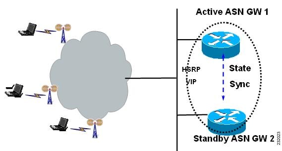
Session Redundancy on the BWG
Subscriber Management
Subscriber information includes session and flows associated with a subscriber context, and is created, updated, or eventually deleted.
Subscriber information includes the following details:
•![]() Authentication info (method, keying info, etc.)
Authentication info (method, keying info, etc.)
•![]() Addressing info (MS MAC, assigned DHCP address, etc.)
Addressing info (MS MAC, assigned DHCP address, etc.)
•![]() VRF name
VRF name
•![]() Username
Username
•![]() Session info (signaling address, and associated timers, etc.
Session info (signaling address, and associated timers, etc.
•![]() Flow info per session (and associated QoS info per flow)
Flow info per session (and associated QoS info per flow)
DHCP and AAA
The BWG supports DHCP relay mode and keeps track of client IP addresses allocated by DHCP servers (and the associated server IP addresses) so that it can relay future DHCP messages from clients to the servers. The client IP address and DHCP server IP address are saved in the subscriber context and are synced to the standby. Once the standby becomes active, it continues to relay DHCP messages from a client to the right server (there can be multiple servers configured: primary/secondary).
IOS AAA is not HA-aware at the moment, so the sync of AAA-related information is part of the session replication.
Dynamic Synchronization
In order for the standby to take over processing from the active in case of a failure, information regarding all sessions and flows on the active are dynamically synchronized to the standby at well defined synchronization points. Separate TLVs are used to synchronize session, flow, and path related information. Dynamic syncing happens for new session/flow events after the standby is at hot-standby state, and after bulk-sync is complete.
The following list identifies current synchronization points:
•![]() During initial network entry, session and flow information is synched to standby only after the Initial Service Flow (ISF) is created.
During initial network entry, session and flow information is synched to standby only after the Initial Service Flow (ISF) is created.
•![]() After the ISF is up, each new flow created on the active is separately synched to the standby.
After the ISF is up, each new flow created on the active is separately synched to the standby.
•![]() Any updates to the service flow will cause the flow to be synched to the standby.
Any updates to the service flow will cause the flow to be synched to the standby.
•![]() Every time an address allocation happens, the flow will be synched to the standby.
Every time an address allocation happens, the flow will be synched to the standby.
•![]() Any changes to the path on the active are synchronized to the standby
Any changes to the path on the active are synchronized to the standby
•![]() During handoff, flow information is synchronized to the standby only after the handoff is complete. Cloned flows are not synched. New flows created on the active as a result of handoff are synchronized to standby by a FLOW UPDATE message that carries modified parameters as result of handoff.
During handoff, flow information is synchronized to the standby only after the handoff is complete. Cloned flows are not synched. New flows created on the active as a result of handoff are synchronized to standby by a FLOW UPDATE message that carries modified parameters as result of handoff.
•![]() Flow synchronization after the transmission of an interim accounting request from the active. This causes FLOW UPDATE messages to be sent from active to standby, and the necessary message carries accounting counters that are sent to AAA as a part of interim accounting update.
Flow synchronization after the transmission of an interim accounting request from the active. This causes FLOW UPDATE messages to be sent from active to standby, and the necessary message carries accounting counters that are sent to AAA as a part of interim accounting update.
Configuring Session Redundancy
The following configuration tasks are required before you can configure session redundancy:
•![]() Configure HSRP on the interface.
Configure HSRP on the interface.
•![]() Configure redundancy inter-device
Configure redundancy inter-device
•![]() Configure SCTP for RF Check pointing
Configure SCTP for RF Check pointing
•![]() Configure Network Time Protocol (NTP) server
Configure Network Time Protocol (NTP) server
•![]() Configure AAA on the active BWG and standby BWG
Configure AAA on the active BWG and standby BWG
To configure session redundancy on the BWG, perform the following tasks:
Configuration Example
This configuration is for AAA only.
On the Active BWG
---------------------------------------------------------------
!
interface Loopback192
ip address 192.168.0.70 255.255.255.255
!
!
aaa group server radius car-sg
server 1.8.70.99 auth-port 1812 acct-port 1813
!
aaa authentication dot1x car_auth_list group car-sg
aaa accounting network car_acct_list start-stop group car-sg
!
!
ip radius source-interface Loopback192
radius-server host 1.8.70.99 auth-port 1812 acct-port 1813
radius-server key r6AAA
radius-server vsa send accounting wimax
radius-server vsa send authentication wimax
!
On the Standby BWG
---------------------------------------------------------------
!
interface Loopback192
ip address 192.168.0.70 255.255.255.255
!
!
aaa new-model
!
!
aaa group server radius car-sg
server 1.8.70.99 auth-port 1812 acct-port 1813
!
aaa authentication dot1x car_auth_list group car-sg
aaa accounting network car_acct_list start-stop group car-sg
!
!
ip radius source-interface Loopback192
radius-server host 1.8.70.99 auth-port 1812 acct-port 1813
radius-server key r6AAA
radius-server vsa send accounting wimax
radius-server vsa send authentication wimax
Sample Configuration of BWG: Active
interface GigabitEthernet0/0.70
description to AAA/DHCP
encapsulation dot1Q 70
ip address 1.8.70.147 255.255.255.0
standby 70 ip 1.8.70.70
standby 70 follow P7_REDUNDANCY
Note ![]() Please reload the BWG if it suffers a time-zone change.
Please reload the BWG if it suffers a time-zone change.
This configuration example includes information about DHCP:
interface Loopback102
ip address 102.0.0.1 255.255.255.0
!
user-group domain eaptls.com2
aaa accounting method-list AAA-ACC1
aaa authentication method-list AAA-AUTHN1
dhcp gateway address 102.0.0.1
dhcp server primary 27.0.0.8
service-flow pre-defined isf profile sf3
service-flow pre-defined secondary 1 profile sf4
vrf VRF_2
Authentication
A subscriber is authenticated using EAP on the active before the sessions/flows are recreated on the standby. The associated MSK, AK context and other credentials need to be transferred to the standby, along with the session stateful data. If geographic redundancy is deployed, this data must be protected. If the standby becomes active after a switchover, and if the same subscriber is re-authenticated on the new active, it follows the same authentication procedure as on the previous active.
Accounting
The accounting start, stop and interim update are only sent from the active. The standby never sends accounting records until it becomes active.
As part of the session/flow recreation on the standby, the IOS AAA database is populated with accounting records for each session/flow. For example, the "class" attribute and accounting session ID are synched from the active to the standby, and are saved to the related accounting record. This ensures that once the standby becomes active, it can send accounting records with the right info.
Synchronization of accounting counters is a function of the AAA interim accounting update feature. If the AAA interim accounting update feature is enabled, then the active BWG sends accounting records to AAA server. And the same event is used as a trigger to initiate a FLOW UPDATE event (which carries accounting counters the same as were sent to AAA server). Conversely, if this feature is disabled on the active, since there is not going to be an accounting update to AAA, there is an absence of triggers to send the accounting update synchronization message to standby. By itself, the BWG SR feature does not implement triggers to synchronize accounting counters.
The accounting session ID is a key attribute used in accounting events (start, stop, interim) and is used to collaborate records on the AAA server. It is a 4-byte unassigned integer, and is assigned uniquely within a ASNWG and increased sequentially until it rolls over. To ensure the new active can continue to generate unique accounting session IDs upon switchover, the new accounting session ID starts from the latest accounting session ID on the prior active.
Subscriber IP Address
Currently, the subscriber IP address is assigned by the DHCP server and a host route is inserted for it. When the standby recreates the subscriber session, the same host route is also inserted on the standby. The standby will not relay any DHCP messages between the DHCP client and the server until it becomes active.
QoS
For BWG Release 1.0 and above, after a flow is created and the QoS parameters for the flow are sent to the BS, the BWG active synchronizes all the QoS parameters to the standby. Out of all of the parameters, the DSCP code for a flow synched to the standby is used to mark the packets once it becomes active.
Statistics and Counters
Statistics and counters are not synched to the standby. Instead, the standby rebuilds them as it processes stateful data from the active to create, modify, and delete sessions/flows. For example, the number of sessions/flows on the standby is updated as the standby processes session/flow creation and deletion. The number of received R6 messages on the standby is accumulated from the moment it becomes active and starts to receive R6 messages.
BWG Load Balancing
When a load balancer is running, it uses the loading information of all the BWGs to select one of them, and forwards an incoming NetEntry message from the BS (with regard to a SS/MS) to the selected BWG.
When Dynamic Feedback Protocol (DFP) is configured, an active BWG periodically sends its loading information to the load balancer. A standby BWG does not send feedback and does not have accurate loading information because it does not process R6 messages and handle user traffic. Once a standby becomes active, it gradually builds accurate load as it processes R6 messages and handles user traffic. So there is an adjusting period before it can send back feedback about its current accurate load.
Data Path and GRE
The data path for a flow is recreated on the standby. The GRE keys for both the upstream and downstream of a flow are synched to the standby. Upon switchover, the new active ensures that any new GRE key allocated locally must not collide with any in-use GRE keys allocated by the previous active.
Version Control
Upgrading from the immediate lower software version to a higher version is supported. Downgrading of software version is not supported. For example, if a redundant pair of BWGs runs on version A, and the next immediate software version is version B, then upgrading from version A to B is supported (but not from B to A). This requires that the higher version understands the stateful data synched from a lower version.
Limitations
The following limitations exist in the Session Redundancy feature on the BWG:
•![]() Synchronization of Accounting Counters
Synchronization of Accounting Counters
This is configurable, and depends upon the AAA interim accounting update feature to be enabled. If the AAA interim accounting feature is disabled, then the default behavior of BWG SR is to not synchronize accounting data/payload counters. This may lead to under charging. For example, if a switchover occurs between two consecutive interim updates, the counts accumulated on the active after the previous interim update are lost, since the new interim update sends only the counts that are accumulated on the new active. Additionally, a STOP could be lost right before the switchover.
Note ![]() Signaling counters are not synched.
Signaling counters are not synched.
Note ![]() For a standalone system, current AAA/Radius counters work accurately. However, when Session Redundancy is enabled, the flow (or session in terms of radius) age can be incorrect if relied upon the current counters. An additional attribute will now be sent from the ASN-GW called "session_elapsed_time" which will reflect the number of seconds since the particular flow started.
For a standalone system, current AAA/Radius counters work accurately. However, when Session Redundancy is enabled, the flow (or session in terms of radius) age can be incorrect if relied upon the current counters. An additional attribute will now be sent from the ASN-GW called "session_elapsed_time" which will reflect the number of seconds since the particular flow started.
•![]() Missing of a Session on the Standby
Missing of a Session on the Standby
Although SCTP provides reliable transport, the stateful data used to replicate a session can be lost due to congestion or max retrials. In this case, the session is not recreated on the standby. In case there is a switchover, this session is lost.
•![]() Stale Session on the Standby
Stale Session on the Standby
For the same reason as above, if a stateful data for a session deletion is lost, then the session is not deleted from the standby while it's gone on the active.
–![]() If there is no switchover before the next session creation of the same subscriber, it's expected that the next synching of creation of a new session for the same subscriber will clean up the stale session.
If there is no switchover before the next session creation of the same subscriber, it's expected that the next synching of creation of a new session for the same subscriber will clean up the stale session.
–![]() If there is a switchover, then the stale session hangs until cleanup by manual intervention or by features like idle/session timeout.
If there is a switchover, then the stale session hangs until cleanup by manual intervention or by features like idle/session timeout.
•![]() Mid-call Abort
Mid-call Abort
If a call setup is in progression but before reaching the first synching point and if there is a switchover, the call setup is aborted, and the subscriber has to retry the call.
Switchover
When switchover occurs, a trap is generated and sent to the NMS system to indicate that the active unit has failed, and the standby has taken over as active. The following behavior is expected:
•![]() Any new GRE key allocated locally must not collide with any in-use GRE keys allocated by the previous active.
Any new GRE key allocated locally must not collide with any in-use GRE keys allocated by the previous active.
•![]() Any new accounting session ID allocated locally must not collide with any in-use accounting session ID allocated by the previous active.
Any new accounting session ID allocated locally must not collide with any in-use accounting session ID allocated by the previous active.
•![]() DHCP relay for a new session is forwarded to a configured DHCP server.
DHCP relay for a new session is forwarded to a configured DHCP server.
•![]() Some of the statistics will have a fresh start.
Some of the statistics will have a fresh start.
•![]() DFP load is rebuilt and sent to the load balancer.
DFP load is rebuilt and sent to the load balancer.
The following list identifies events which will cause a switchover:
•![]() Router reload/crash because of reasons like software crash, CPU hogging, etc.
Router reload/crash because of reasons like software crash, CPU hogging, etc.
•![]() HSRP tracks interfaces based on the configuration. On detecting interface flap <on-off transition> HSRP will enforce reload current active which will cause switchover of activity
HSRP tracks interfaces based on the configuration. On detecting interface flap <on-off transition> HSRP will enforce reload current active which will cause switchover of activity
•![]() Manual intervention to switch activity from current active router to redundant hot standby. This can be accomplished using the following commands:
Manual intervention to switch activity from current active router to redundant hot standby. This can be accomplished using the following commands:
–![]() redundancy switch-activity force
redundancy switch-activity force
This command is used to switch activity from current active to current hot standby. Issuing the command causes the current router to reload, the current hot standby to become active, and when the current active router comes back up it assumes the role of hot standby.
–![]() reload
reload
This is normal router reload command that causes switchover. The current active router will reload, and the current hot standby will become active.
BWG Load Balancing
The purpose of load balancing is scalability of the BWG without distributing intelligence across base stations. This scalability is provided by load balancing across a set of BWGs, while representing the cluster as a single BWG from the perspective of the BS. Thus, the base station will have a single point of contact. And any new BWG that is added to the system will not impact the base station provisioning.
Note ![]() Server Load Balancing and Session Redundancy are only available on Cisco 7600 SAMI platform.
Server Load Balancing and Session Redundancy are only available on Cisco 7600 SAMI platform.
BWG Load Balancing is based on the IOS Server Load Balancing (SLB) feature. BSs are configured with the virtual IP address of the SLB as the BWG ID. The BWG selection flow for load balancing is illustrated below. Both dispatch mode and directed mode are supported. DFP is supported for the SLB to discover the load on the real BWGs.
Note ![]() In Release 1.0 and above, the SLB sticky feature and BWG handover call flows are not supported.
In Release 1.0 and above, the SLB sticky feature and BWG handover call flows are not supported.
The session created on SLB, when the initial context request is processed, is maintained for a configurable time period to handle the re-transmission. During this period, if a re-transmission of context request is detected for a given MS/SS, SLB directs the re-transmission request to the same real BWG, that was selected for the first context request.
DFP is supported for the SLB to discover the load on the real BWGs. Each real BWG has a limit on the number of maximum sessions it supports. Real BWG calculated load on itself is based on the existing number of sessions versus the maximum sessions that it can support, memory usage, and bandwidth usage and reports the load to SLB. SLB directs the initial context request to one of the real BWGs based on either the round robin or least connections method. An BWG will not accept any more sessions if its load as calculated by DFP is 100%. Thus, this mechanism also supports CAC.
Figure 2-2
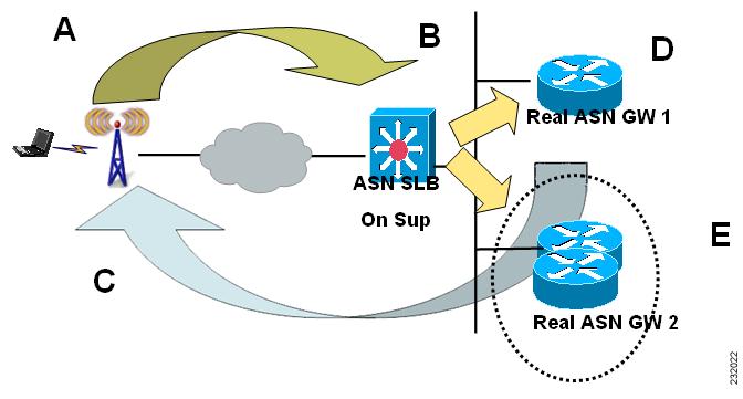
Server Load Balancing on the BWG
BWG Selection
•![]() During Initial Network Entry phase, the BS sends the NetEntry MS Pre-Attachment Request corresponding to the SS/MSS to the BWG configured as the default.
During Initial Network Entry phase, the BS sends the NetEntry MS Pre-Attachment Request corresponding to the SS/MSS to the BWG configured as the default.
•![]() This BWG sends the NetEntry MS Pre-Attachment Response to the BS. The response may contain the IP address of an alternate Authenticator ID that can handle subsequent transactions corresponding to the SS/MSS. The BS, on receiving the NetEntry MS Pre-Attachment Response, sends the NetEntry MS State Change Ack to complete the transaction.
This BWG sends the NetEntry MS Pre-Attachment Response to the BS. The response may contain the IP address of an alternate Authenticator ID that can handle subsequent transactions corresponding to the SS/MSS. The BS, on receiving the NetEntry MS Pre-Attachment Response, sends the NetEntry MS State Change Ack to complete the transaction.
•![]() All subsequent transactions corresponding to the SS/MSS occur between the BS and the BWG specified in the NetEntry MS Pre-Attachment Response Message.
All subsequent transactions corresponding to the SS/MSS occur between the BS and the BWG specified in the NetEntry MS Pre-Attachment Response Message.
Modes of Operation
There are two operation modes on the BWG:
•![]() Dispatched Mode— In this mode packets are sent to the real server without any change to the original packet. A loopback is configured in the real server with an IP equal to virtual IP, and it replies back with virtual IP address as the source address.
Dispatched Mode— In this mode packets are sent to the real server without any change to the original packet. A loopback is configured in the real server with an IP equal to virtual IP, and it replies back with virtual IP address as the source address.
•![]() Directed Mode—The packet's destination IP address is rewritten to choose the BWG's IP address, and no loopback with the virtual ip address is configured on the BWG.
Directed Mode—The packet's destination IP address is rewritten to choose the BWG's IP address, and no loopback with the virtual ip address is configured on the BWG.
In both modes the selected BWG sends the pre-attachment response.
Configuring Load Balancing
This section lists configuration details regarding server load balancing. These configuration details are mainly for Directed Mode unless otherwise specified.
Load Balancing Configuration Task List
This section lists the tasks used to configure load balancing. Required and optional tasks
are indicated.
1. ![]() On the Cisco IOS SLB, complete the following tasks:
On the Cisco IOS SLB, complete the following tasks:
a. ![]() Configuring a Server Farm and Real Server, (Required)
Configuring a Server Farm and Real Server, (Required)
b. ![]() Configuring a Virtual Server, (Required)
Configuring a Virtual Server, (Required)
c. ![]() Configuring DFP Support, (Optional, but recommended)
Configuring DFP Support, (Optional, but recommended)
2. ![]() On the real BWG, complete the following tasks:
On the real BWG, complete the following tasks:
a. ![]() Configuring a Loopback Interface for SLB, (Required if using dispatched mode)
Configuring a Loopback Interface for SLB, (Required if using dispatched mode)
b. ![]() Configuring DFP Support on the BWG, (Optional, but recommended)
Configuring DFP Support on the BWG, (Optional, but recommended)
Configuring Cisco IOS SLB for Load Balancing
This section describes how to configure a Server Farm and a Real Server. To configure a Cisco IOS SLB server farm, use the following commands, beginning in global configuration mode:
Sample Configuration
ip slb serverfarm ASNGW-SR-SF
nat server
probe PINGPROBE
!
real 11.11.11.50
weight 0
inservice
!
real 11.11.11.70
weight 0
inservice
Configuring Real BWG
Configuring the BWG for Load Balancing
To configure load balancing on the BWG, complete the tasks in the following sections:
•![]() Configuring a Loopback Interface for SLB,
Configuring a Loopback Interface for SLB,
•![]() Configuring the BWG as a DFP Agent, (Optional, but recommended)
Configuring the BWG as a DFP Agent, (Optional, but recommended)
Configuring a Loopback Interface for SLB
To enable load balancing, a loopback interface must be configured with the same IP address as the virtual server on the Cisco IOS SLB on each BWG in a farm.
To create a loopback interface, use the following commands, beginning in global configuration mode:
Configuring the BWG as a DFP Agent
To define the port number to be used by the DFP manager (the Cisco IOS SLB in this instance) to connect to the DFP agent; enter the following commands in order, beginning in global configuration mode:
Sample Configuration
ip dfp agent agw
port 5555
inservice
To configure load balancing on the BWG, perform the following task:
BWG Configuration Example
Please note that following sample configuration applies only to SAMI platform.
SLB Related Configuration of Supervisor Card
7606-R6-sup720#show running-configuration | section slb
ip dfp agent slb
port 5555
ip slb probe PINGPROBE ping
interval 3
faildetect 3
ip slb serverfarm ASNGW-SR-SF
nat server
probe PINGPROBE
!
real 11.11.11.50
weight 0
inservice
!
real 11.11.11.70
weight 0
inservice
ip slb vserver V-ASNGW-SR
virtual 50.70.80.100 udp 2231 service asn r6
serverfarm ASNGW-SR-SF
idle asn r6 request 90
inservice
ip slb dfp
agent 11.11.11.50 5555 10 0 5
agent 11.11.11.70 7777 10 0 5
7606-R6-sup720#
Sample configuration of a real BWG for above configuration of Supervisor card.
bwg-real-s4p5# show running-configuration | section dfp
ip dfp agent agw
port 5555
inservice
bwg-real-s4p5#
asngw-real-s4p7#sh runn | section dfp
ip dfp agent agw
port 7777
inservice
bwg-real-s4p7#
Verifying the Configuration
To verify that load balancing is enabled on the BWG, perform the following tasks:
Configuration Example
Here is a sample configuration for SLB show commands on the BWG:
7606-R6-sup720#show ip slb sessions asn r6
vserver MSID Base Station real state
----------------------------------------------------------------------------
7606-R6-sup720#show ip slb sessions asn r6
vserver MSID Base Station real state
----------------------------------------------------------------------------
V-ASNGW-SR 0000AAAAC38ECCCC 50.35.50.1 11.11.11.50 ASNR6_ESTAB
V-ASNGW-SR 0000AAAAC392CCCC 50.35.50.1 11.11.11.50 ASNR6_ESTAB
V-ASNGW-SR 0000AAAAC396CCCC 50.35.50.1 11.11.11.50 ASNR6_ESTAB
V-ASNGW-SR 0000AAAAC39ACCCC 50.35.50.1 11.11.11.50 ASNR6_ESTAB
V-ASNGW-SR 0000AAAAC39ECCCC 50.35.50.1 11.11.11.50 ASNR6_ESTAB
< S N I P P E D >
7606-R6-sup720#show ip slb vserver detail
V-ASNGW-SR, state = OPERATIONAL, v_index = 7, interface(s) = <any>
virtual = 50.70.80.100/32:2231, UDP, service = ASNR6, advertise = TRUE
server farm = ASNGW-SR-SF, delay = 10, idle = 3600
asnr6: request idle = 90, Parse error pkt drops= 56,
Number of reject responses = 0
sticky: <none>
sticky: group id = 0
synguard counter = 0, synguard period = 0
conns = 101, total conns = 509069, syns = 0, syn drops = 0
standby group = None
7606-R6-sup720#show ip slb reals
real farm name weight state conns
-------------------------------------------------------------------
11.11.11.50 ASNGW-SR-SF 92 OPERATIONAL 83
11.11.11.70 ASNGW-SR-SF 92 OPERATIONAL 18
7606-R6-sup720#show ip slb serv
7606-R6-sup720#show ip slb serverfarms
server farm predictor nat reals bind id interface(s)
--------------------------------------------------------------------------
ASNGW-SR-SF ROUNDROBIN S 2 0 <any>
7606-R6-sup720#show ip slb sessions asn r6 de
7606-R6-sup720#show ip slb sessions asn r6 detail
V-ASNGW-SR, client = 50.35.50.1:2231, virtual = 50.70.80.100:2231
state = ASNR6_ESTAB, real = 11.11.11.50
Key = 0000AAAAC38ECCCC, retry = 1
V-ASNGW-SR, client = 50.35.50.1:2231, virtual = 50.70.80.100:2231
state = ASNR6_ESTAB, real = 11.11.11.50
Key = 0000AAAAC392CCCC, retry = 1
V-ASNGW-SR, client = 50.35.50.1:2231, virtual = 50.70.80.100:2231
state = ASNR6_ESTAB, real = 11.11.11.50
Key = 0000AAAAC396CCCC, retry = 1
V-ASNGW-SR, client = 50.35.50.1:2231, virtual = 50.70.80.100:2231
state = ASNR6_ESTAB, real = 11.11.11.50
Key = 0000AAAAC39ACCCC, retry = 1
V-ASNGW-SR, client = 50.35.50.1:2231, virtual = 50.70.80.100:2231
state = ASNR6_ESTAB, real = 11.11.11.50
Key = 0000AAAAC39ECCCC, retry = 1
V-ASNGW-SR, client = 50.35.50.1:2231, virtual = 50.70.80.100:2231
state = ASNR6_ESTAB, real = 11.11.11.50
< S N I P P E D >
7606-R6-sup720#
Configuring a Virtual Server
To configure a Cisco IOS SLB virtual server, use the following commands, beginning in global configuration mode:
Sample Configuration
Router-SLB(config)# ip slb vserver V-ASNGW-SR
Router-SLB(config-slb-vserver)# virtual 50.70.80.100 udp 2231 service asn r6
Router-SLB(config-slb-vserver)#serverfarm ASNGW-SR-SF
Router-SLB(config-slb-vserver)# idle asn r6 request 90
Router-SLB(config-slb-vserver)#inservice
Configuring DFP Support
You can define Cisco IOS SLB as a DFP manager, as a DFP agent for another DFP manager (such as Distributed Director), or as both at the same time. Depending on your network configuration, you might enter the commands for configuring Cisco IOS SLB as a DFP manager and the commands for configuring Cisco IOS SLB as a DFP agent on the same device or on different devices.
To configure Cisco IOS SLB as a DFP manager, and to identify a DFP agent with which Cisco IOS SLB can initiate connections, use the following commands, beginning in global configuration mode:
Sample Configuration
Router-SLB(config) # ip slb dfp
Router-SLB(config-slb-dfp)# agent 11.11.11.50 5555 10 0 5
Router-SLB(config-slb-dfp)# agent 11.11.11.70 7777 10 0 5
SLB Stickiness Support
SLB for BWG supports load balancing of any R4 or R6 control plane messages. Release 1.0 and above supports basic load balancing for only the Pre-Attachment Message.
BWG Release 2.0 supports the following features:
•![]() Any Wimax message types towards the BWG with or without sticky entries, both for R4 and R6 reference points.
Any Wimax message types towards the BWG with or without sticky entries, both for R4 and R6 reference points.
•![]() If "no sticky entry" is available, all Wimax R6/R4 messages to the Wimax port are load balanced based on the current DFP (or weight algorithms) to the specific "real" BWG.
If "no sticky entry" is available, all Wimax R6/R4 messages to the Wimax port are load balanced based on the current DFP (or weight algorithms) to the specific "real" BWG.
•![]() If there is a sticky MSID already present, the BWG SLB forwards any Wimax control plane messages to the respective "real" BWG.
If there is a sticky MSID already present, the BWG SLB forwards any Wimax control plane messages to the respective "real" BWG.
Update Sticky
The BWG sends an update notification to the SLB. Once the authentication is completed, the BWG has the user name (NAI) for the MS. As soon as the ISF (first flow) is created, the BWG sends the sticky update to the SLB server, and includes the NAI value.
Deleting Stickiness
The following two scenarios cause the SLB to delete stickiness:
•![]() The BGW signals when a specific subscriber session is deleted to the SLB, so that the sticky entry is removed.
The BGW signals when a specific subscriber session is deleted to the SLB, so that the sticky entry is removed.
•![]() When the "real" BGW fails, all sticky entries corresponding to the real BWG are deleted.
When the "real" BGW fails, all sticky entries corresponding to the real BWG are deleted.
Stateful Redundancy of SLB
To ensure reliability, the BWG SLB supports stateful switchover of the sticky entries, across the primary and standby supervisors.
Messages Between BWG and SLB
Sticky Update Notification
This message is used by the BWG to notify the SLB about the NAI update for the sticky.
Sticky Deletion Notification
This message is sent when the last PDP in the session gets deleted. This allows the SLB to delete the corresponding sticky entry.
SRC IP |
Virtual Template IP (real IP) |
|
DST IP |
ASNLB's virtual IP |
|
UDP HDR |
SRC_PORT |
XXXX (?) |
DST_PORT |
XXXX |
|
MSG HDR |
MSG_TYPE |
2 |
MSID (6 bytes) |
||
Configuring SLB Support
To configure the BWG to perform SLB with Stickiness, perform the following tasks:
Lawful Intercept
Lawful Intercept (LI) ensures that Cisco meets worldwide LI requirements, including the support for CALEA (Communications Assistance for Law Enforcement Act).
The packet matching is based on the Mobile Subscriber Identity (MSID) of a given subject.
Configuring the BWG for Lawful Intercept
SNMP Host and User Setup
In order to set or view the variables in a MIB, you must first become an authorized user from an authorized host. Configure the following commands on the BWG to run Lawful Intercept.
1. ![]() Create a View Having Access to the Appropriate MIBs
Create a View Having Access to the Appropriate MIBs
2. ![]() Create a Group Having Access to the View:
Create a Group Having Access to the View:
|
|
|
|
Step 1 |
router#snmp-server group group name> v3 priv read view name write view name notify view name |
Configures the BWG create a group that has access to a view. |
3. ![]() Create a User who is a Member of the Group. You must create a user who has read and write privileges for the new group:
Create a User who is a Member of the Group. You must create a user who has read and write privileges for the new group:
|
|
|
|
Step 1 |
router#snmp-server user user name group name v3 auth sha/md5 auth password priv 3des/aes/des priv password |
Creates a user to have read and write privileges for a new group. |
4. ![]() Create a Host from which the User will Connect. You must specify the host from which the user is allowed to connect the BWG:
Create a Host from which the User will Connect. You must specify the host from which the user is allowed to connect the BWG:
|
|
|
|
Step 1 |
router#snmp-server host IP address version 3 priv user name |
Specifies the host from which the user is allowed to connect to the BWG. |
5. ![]() Setup the Engine Identifier for testing purposes, even though one may not be required in a production environment:
Setup the Engine Identifier for testing purposes, even though one may not be required in a production environment:
|
|
|
|
Step 1 |
router#snmp-server engineID local engine
ID
|
Specifies the engine identifier. |
Steps to Setup BWG LI
Here are the steps to set up BWG Lawful Intercept:
1. ![]() Setup the Mediation Device
Setup the Mediation Device
2. ![]() Setup the generic stream
Setup the generic stream
3. ![]() Setup the specific stream
Setup the specific stream
4. ![]() Enable the generic stream
Enable the generic stream
Setup Mediation Device
Set the following variables in the CISCO-TAP2-MIB from an authorized host:
Other transport options are also available. They may require additional fields to be configured.
Setup Generic Stream
Set the following variables in the CISCO-TAP2-MIB from an authorized host:
In our case, set the "Status" variable to 5, which denotes the "Create and Wait" status. Then, set the "Type" variable to 4 to denote the Mobility intercept stream. Finally, set the "InterceptEnable" variable to 2, which denotes false, until you associate a specific stream to the tap.
Setup the Specific Mobility Stream
Set the following variables in the CISCO-MOBILITY-TAP-MIB from an authorized host:
Enable the Generic Stream
Set the generic stream's "Status" variable to 1 to activate the row. Finally, set the generic stream's "InterceptEnable" to "true" to activate the tap.
Intercept Provisioning
The Intercepts are provisioned through SNMPv3.The provisioning occurs in three stages. First, the individual placing the intercepts must configure a valid Mediation Device (MD) by configuring the appropriate variables explained in the CISCO-TAP2-MIB. After the MD is configured, you must configure a generic stream, which is also described in the CISCO-TAP2-MIB. Finally, you must choose a specific stream that will be associated with the generic stream.
In the case of the BWG, the Mobility Stream defined by the CISCO-MOBILITY-TAP-MIB is the specific stream. Currently, the BWG only supports tapping based on the Mobile Subscriber ID for the Mobility Stream. Thus, when configuring the Mobility Stream tap, set the SubscriberID field to the desired MSID, whose traffic you want to intercept. Then, set the SubscriberIDType field to "MSID".
Packet Intercept
Conceptually, the Lawful Intercept requirements on the BWG look like packet replication. After a subscriber/host is identified, the packets for this subscriber/host are decapsulated and the IP packets are replicated. The original packet is then sent to the original destination. The replicated and encapsulated packet is sent to the mediation device. The BWG does not look into the type of the packet, just replicates the received packets in either direction and sends the replicated packets to the mediation device. Thus, the BWG could replicate voice as well as data packets.
WiMAX NWG does not define how the replicated packets should be encapsulated. The CISCO-TAP2-MIB allows you to configure the MD to encapsulate and transport the replicated packets using PacketCable UDP, RTP with Nack resilience, TCP with head of line blocking, and SCTP with head of line blocking. The current implementation of the BWG uses UDP (PacketCableTM) as the encapsulation scheme.
SNMP Options Not Currently Supported for Lawful Intercept
Currently the BWG does not support the Debug User options in the CISCO-TAP2-MIB. Specifically, the following objects in the CISCO-TAP2-MIB are not currently supported:
•![]() cTap2DebugUserTable
cTap2DebugUserTable
•![]() cTap2DebugUserEntry
cTap2DebugUserEntry
•![]() CTap2DebugUserEntry
CTap2DebugUserEntry
•![]() cTap2DebugUserName
cTap2DebugUserName
•![]() cTap2DebugUserTimeout
cTap2DebugUserTimeout
•![]() cTap2DebugUserStorageType
cTap2DebugUserStorageType
•![]() cTap2DebugUserStatus
cTap2DebugUserStatus
Configuring the BWG
This section describes various other configuration tasks that you need to perform to make the BWG function properly. It includes the following topics:
Configuring SNMP on the BWG
This section provides information on how to configure Simple Network Management Protocol (SNMP) on the BWG. It contains the following configuration tasks:
•![]() Configuring SNMP Access in Routers
Configuring SNMP Access in Routers
•![]() Configuring SNMP-Server Trap-Source
Configuring SNMP-Server Trap-Source
Configuring SNMP Access in Routers
To set up the community access string to permit access to the Simple Network Management Protocol (SNMP), perform the following tasks:
Configuring SNMP-Server Host
To specify the recipient of an Simple Network Management Protocol notification operation, perform the following tasks:
This command is disabled by default. No notifications are sent. If you enter this command with no keywords, the default is to send all trap types to the host. No informs will be sent to this host.
If no version keyword is present, the default is version 1. The no snmp-server host command with no keywords will disable traps, but not informs, to the host. In order to disable informs, use the no snmp-server host informs command.
Configuring SNMP-Server Trap-Source
To specify the interface (and the corresponding IP address) that an Simple Network Management Protocol trap should originate from, perform the following task:
Configuring SNMP Traps
To enable the router to send Simple Network Management Protocol traps or informs (SNMP notifications), perform the following task:
Configuration Examples
The following example enables the router to send all traps to the host specified by the name "myhost.cisco.com", using the community string defined as "public":
snmp-server enable traps
snmp-server host myhost.cisco.com public
The following example enables the router to send Frame Relay and environmental monitor traps to the host "myhost.cisco.com" using the community string "public":
snmp-server enable traps frame-relay
snmp-server enable traps envmon temperature
snmp-server host myhost.cisco.com public
The following example will not send traps to any host. The BGP traps are enabled for all hosts, but the only traps enabled to be sent to a host are ISDN traps (which are not enabled in this example).
snmp-server enable traps bgp
snmp-server host bob public isdn
router(config)# [no] logging snmp-authfail
Note ![]() Using the logging snmp-authfail command enables all SNMP authentication failure logging messages. The no version of this command will disable the logging of authentication failure messages.
Using the logging snmp-authfail command enables all SNMP authentication failure logging messages. The no version of this command will disable the logging of authentication failure messages.
Note ![]() If you do not use the SNMP management tools of the router to monitor PPP sessions, you can prevent the virtual-access sub interfaces from being registered with the SNMP functionality of the router and using memory by using the no virtual-template snmp command. For example:
If you do not use the SNMP management tools of the router to monitor PPP sessions, you can prevent the virtual-access sub interfaces from being registered with the SNMP functionality of the router and using memory by using the no virtual-template snmp command. For example:
router(config)# [no] virtual-template snmp
SNMP Configuration Examples on the BWG
Logging
=========
!
logging snmp-authfail
logging queue-limit 100
logging buffered 1000000
enable password lab
!
Virtual Template
=============
!
no virtual-template snmp
!
SNMP Traps
==========
snmp-server community private RW
snmp-server trap-source GigabitEthernet0/2
snmp-server enable traps snmp authentication linkdown linkup coldstart warmstart
snmp-server enable traps vrrp
snmp-server enable traps ds1
snmp-server enable traps tty
snmp-server enable traps eigrp
snmp-server enable traps casa
snmp-server enable traps cnpd
snmp-server enable traps pw vc
snmp-server enable traps syslog
snmp-server enable traps isdn call-information
snmp-server enable traps isdn layer2
snmp-server enable traps isdn chan-not-avail
snmp-server enable traps isdn ietf
snmp-server enable traps ds3
snmp-server enable traps atm subif
snmp-server enable traps channel
snmp-server enable traps ima
snmp-server enable traps srp
snmp-server enable traps flash insertion removal
snmp-server enable traps hsrp
snmp-server enable traps config
snmp-server enable traps entity
snmp-server enable traps fru-ctrl
snmp-server enable traps cpu threshold
snmp-server enable traps config-copy
snmp-server enable traps envmon
snmp-server enable traps aaa_server
snmp-server enable traps agw
snmp-server enable traps bgp
snmp-server enable traps ospf state-change
snmp-server enable traps ospf errors
snmp-server enable traps ospf retransmit
snmp-server enable traps ospf lsa
snmp-server enable traps ospf cisco-specific state-change nssa-trans-change
snmp-server enable traps ospf cisco-specific state-change shamlink interface-old
snmp-server enable traps ospf cisco-specific state-change shamlink neighbor
snmp-server enable traps ospf cisco-specific errors
snmp-server enable traps ospf cisco-specific retransmit
snmp-server enable traps ospf cisco-specific lsa
snmp-server enable traps pim neighbor-change rp-mapping-change invalid-pim-message
snmp-server enable traps ipmulticast
snmp-server enable traps mvpn
snmp-server enable traps msdp
snmp-server enable traps rsvp
snmp-server enable traps frame-relay
snmp-server enable traps frame-relay subif
snmp-server enable traps ipsla
snmp-server enable traps stun
snmp-server enable traps dlsw
snmp-server enable traps bstun
snmp-server enable traps pppoe
snmp-server enable traps l2tun session
snmp-server enable traps l2tun pseudowire status
snmp-server enable traps ipmobile
snmp-server enable traps frame-relay multilink bundle-mismatch
snmp-server enable traps dsp card-status
snmp-server enable traps dsp oper-state
snmp-server enable traps event-manager
snmp-server enable traps alarms informational
snmp-server host 171.71.129.34 public
MIB Support
The BWG supports a Management Information Base (MIB) that describes objects that enable users and network management to remotely monitor the BWG using SNMP commands. The BWG supports two separate MIBs:
One contains global system information and parameters, base-station information, subscriber, flow, traffic and trap notification information.
The second contains information about the R6 signaling protocol information used between the base-station and the BWG. This includes overall gateway R6 information, and information per base-station.
The BWG MIB variables are not synchronized across a fail-over. Many MIB variables can be recreated on the standby from the synchronized state data. The NMS attempts to handle such a situation, and any inconsistencies in MIB data that result from this approach. The existing RF/CF MIB is also available.
Verifying MIB Support
To display various MIB parameters, perform the following tasks:
Configuration Examples
Here is sample output for the show wimax agw command:
router# show wimax agw
Access network gateway version 0.1, service is enabled
AGW listening on UDP control port 2231
Maximum Number of base station 500 allowed
Maximum Number of subscriber 20000 allowed
Number of signalling paths created 0
Number of brearer paths created 0
Number of subscribers connected 0
Number of sessions created 0
Number of flows created 0
Traffic Sent 0 packets, 0 bytes
Traffic Rcvd 0 packets, 0 bytes
Number of framed routes
Number of subscribers using the framed routes
Current number of user auto-provisioned sessions
The traffic is split for IP CS and ETH CS.
Here is sample output for the show wimax agw user-group command:
router# show wimax agw user-group
AGW User-Group-List
There are 3 user-groups configured in list wimax
User group domain name any
User-Group overwritten Counter 0
Service mode operational
Sessions 0 associated
IP-GRE Traffic Sent 0 packets, 0 bytes
IP-GRE Traffic Received 0 packets, 0 bytes
Eth-GRE Traffic Sent 0 packets, 0 bytes
Eth-GRE Traffic Received 0 packets, 0 bytes
Ingress Address filtering 0 packets, 0 bytes
Traffic Received redirected 0 packets, 0 bytes
User group domain name cisco
Service mode operational
Sessions 0 associated
Traffic Sent 0 packets, 0 bytes
Traffic Received 0 packets, 0 bytes
Ingress Address filtering 0 packets, 0 bytes
User group domain name unauthenticated
Service mode operational
Sessions 0 associated
Traffic Sent 0 packets, 0 bytes
Traffic Received 0 packets, 0 bytes
Ingress Address filtering 0 packets, 0 bytes
router#show wimax agw user-group brief ?
Name Sessions Pkts-Tx Bytes-Tx Pkts-Rx Bytes-Rx VRF
any 0 0 0 0 0
cisco 0 0 0 0 0
unauthenticated 0 0 0 0 0
router#show wimax agw user-group any ?
brief Brief output
| Output modifiers
<cr>
router#show wimax agw user-group any
User group domain name any
--------------------------------------
Service mode operational
Sessions 0 associated
Traffic Sent 0 packets, 0 bytes
Traffic Recevied 0 packets, 0 bytes
Ingress Address filtering 0 packets, 0 bytes
router#show wimax agw user-group any brief
Name Sessions Pkts-Tx Bytes-Tx Pkts-Rx Bytes-Rx VRF
any 0 0 0 0 0
router#show wimax agw user-group name ?
WORD Enter User-group Name
router#show wimax agw user-group name cisco ?
brief Brief output
| Output modifiers
<cr>
router#show wimax agw user-group name cisco
User group domain name cisco
--------------------------------------
Service mode operational
Sessions 0 associated
Traffic Sent 0 packets, 0 bytes
Traffic Recevied 0 packets, 0 bytes
Ingress Address filtering 0 packets, 0 bytes
router#show wimax agw user-group name cisco brief ?
| Output modifiers
<cr>
router#show wimax agw user-group name cisco brief
Name Sessions Pkts-Tx Bytes-Tx Pkts-Rx Bytes-Rx VRF
cisco 0 0 0 0 0
router#show wimax agw user-group unauthenticated ?
brief Brief output
| Output modifiers
<cr>
router#show wimax agw user-group unauthenticated
User group domain name unauthenticated
--------------------------------------
Service mode operational
Sessions 0 associated
Traffic Sent 0 packets, 0 bytes
Traffic Recevied 0 packets, 0 bytes
Ingress Address filtering 0 packets, 0 bytes
asn#sh wimax agw user-group unauthenticated b
asn#sh wimax agw user-group unauthenticated brief ?
| Output modifiers
<cr>
router#show wimax agw user-group unauthenticated brief
Name Sessions Pkts-Tx Bytes-Tx Pkts-Rx Bytes-Rx VRF
unauthenticated 0 0 0 0 0
Here is sample output for the show wimax agw statistics command:
router# show wimax agw statistics
AGW Statistics
Message function type Undefined(0/0x0)
Message function type Data Path(3/0x3)
Message type Deregistration Request(4/0x4)
Number of messages sent 0
Number of messages received 0
Number of messages resent 0
Message type Deregistration Response(5/0x5)
Number of messages sent 0
Number of messages received 0
Number of messages resent 0
Message type Deregistration Ack(6/0x6)
Number of messages sent 0
Number of messages received 0
Number of messages resent 0
Message type Registration Request(12/0xC)
Number of messages sent 0
Number of messages received 0
Number of messages resent 0
Message type Registration Response(13/0xD)
Number of messages sent 0
Number of messages received 0
...
Here is sample output for the show wimax agw statistics dhcp-relay command:
router# show wimax agw statistics dhcp-relay
AGW DHCP Statistics
Tx to DHCP server Discover 0, Request 0
Tx to DHCP server Release 0, Decline 0
Tx to DHCP server Inform 0
Rx from DHCP server Offer 0, Ack 0
Rx from DHCP server Nak 0, Unknown 0
This output gives the statistics of DHCP messages that are relayed through the BWG. If the BWG happened to initiate any DHCP messages, these counters are not incremented.
Here is sample output for the show wimax agw statistics internal command:
Router# show wimax agw statistics internal
Last clearing of "show wimax agw statistics internal" counters 3d23h
Signalling plane related statistics
Signal packets processed messages 483
Signal packets has pending messages 0
Signal packets requeued messages 0
Signal packets dropped too many pending messages 0
Signal packets dropped service disabled 0
Signal packets dropped service not ready 0
Signal packets dropped no encapsulation interface 0
Signal packets dropped CAC denied request 0
Signal packets disposed by agw 0
Data plane related statistics
Data packets not ours encapsulation 0
Data packets not ours encapsulation address 0
Data packets not ours service disabled 0
Data packets not ours invalid protocol type 0
Data packets dropped invalid ip len 0
Data packets dropped absent key data 0
Data packets dropped flow not found 21
Data packets dropped flow path not found 0
Data packets dropped flow path invalid src address 0
Data packets dropped session not found 0
Data packets dropped subscriber not found 0
Data packets dropped checksum error 0
Data packets dropped ingress filtering 0
Data packets dropped sequence number mismatch 0
Data packets dropped invalid redirect address 0
Data packets dropped throttling of punts from cef to process 0
Data packets dropped gateway learning from upstream data packets 0
Data packets dropped non-ARP and non-DHCP L2 multicast/broadcast data packets 0
Data packets punted fragmented 0
Data packets punted from cef path to process path 0
Other related statistics
Number of N/w behind MS in usrgrp enabled 0
Total subscriber created 41
Total subscriber deleted 45
Total session created 41
Total session deleted 45
Total flow created 4
Total flow deleted 7
Total host created 0
Total host deleted 0
Total signalling path created 3
Total signalling path deleted 3
Total data path created 2
Total data path deleted 2
Number of hosts rejected 0
Number of packets dropped due to Static IP Host not allowed 0
Number of static hosts aged out 0
Total sessions rejected due to unapproved BS 0
Configuration related statistics
Service flow profile not found 0
QoS profile not found 0
Classifier profile not found 0
Sla profile not found 0
Handoff related statistics
Total handoffs succeeded 0
Total handoff failed 0
Total cmac key update succeeded 0
Total cmac key update failed 0
Total security key exchange succeeded 0
Total security key exchange failed 0
Miscellaneous statistics
Maximum Subscriber exceeded 0
Maximum BS exceeded 0
MIB Enhancements for BWG Release 1.1
The BWG Management Information Base (MIB) is updated to add Ethernet CS related counters of packets/bytes sent/received. The following MIB objects have been updated in BWG Release 1.1:
•![]() Includes the new EthCS related pkt/bytes sent/receive variables.
Includes the new EthCS related pkt/bytes sent/receive variables.
•![]() Includes a description of packets/bytes sent/receive counters that were modified.
Includes a description of packets/bytes sent/receive counters that were modified.
For example, "The total number of Data Packets received" has been modified to "The total number of IP Data Packets received"
ASN GW Global Statistics
•![]() The total number of IP Data Packets received
The total number of IP Data Packets received
•![]() The total number of IP Data Packets Sent
The total number of IP Data Packets Sent
•![]() The total number of IP Data bytes received
The total number of IP Data bytes received
•![]() The total number of IP Data bytes sent
The total number of IP Data bytes sent
•![]() The total number of Ethernet CS Data Packets received
The total number of Ethernet CS Data Packets received
•![]() The total number of Ethernet CS Data Packets Sent
The total number of Ethernet CS Data Packets Sent
•![]() The total number of Ethernet CS Data bytes received
The total number of Ethernet CS Data bytes received
•![]() The total number of Ethernet CS Data bytes sent
The total number of Ethernet CS Data bytes sent
•![]() Total number of hosts rejected
Total number of hosts rejected
•![]() Total number of static hosts aged out
Total number of static hosts aged out
The MIB also includes new objects for statistics related to ARP (total number of ARP requests received, total number of ARP replies sent, total number of ARP packets dropped), rejected host, and aged out static hosts.
GRE Keying
A GRE key is allocated per service flow in each direction. The GRE keys are exchanged using the RR-Request used to create the Data Path bearer. The GRE keys that correspond to the BWG are allocated by the BWG and sent to the BS during creation of the service flow using the RR-Request. Similarly, the GRE key values corresponding to the BS are allocated by the BS and sent to the BWG using the RR-Response message.
During Inter-BS mobility, new keys are allocated by the Base-station. The BWG keeps the same GRE keys.
The BWG allocates the GRE keys such that the values are not assigned immediately upon release.
VRF Support
A user-group can be configured with virtual route forwarding (VRF) support. This allows you to create an internal VRF entity to connect all traffic to/from the specific user-group.
QoS Support
QoS Support refers to both airlink QoS as well as mapping on the network. The ASNGW is responsible for sending down the qos parameters to the Base-station for creating appropriate service flows.
•![]() Certain hosts can be given additional quality of service parameters
Certain hosts can be given additional quality of service parameters
•![]() A new R6 bearer (service flow) may be created corresponding to the hosts IP address. Multiple host can use this service flow
A new R6 bearer (service flow) may be created corresponding to the hosts IP address. Multiple host can use this service flow
•![]() The mapping of the host to the new R6 service flow is created, and communicated to the BS/MS via the RR-Request.
The mapping of the host to the new R6 service flow is created, and communicated to the BS/MS via the RR-Request.
DSCP Marking Per Service Flow
Each service flow is mapped uniquely to a Diffserv Code Point (DSCP). This DSCP value is used to mark the outer IP header for downstream packets by the BWG, and by the BS for upstream packets.
The inner IP header for upstream and downstream packets is set by the BWG as per the mapping for the service flow, unless explicitly disabled by a CLI.
ACLs
ACLs are supported, and can be configured at a per-user group basis. This applies to all users that connect to the same user-group.
Source IP Address Validation
For all uplink packets, the allocated IP address for the corresponding MS or service flow is validated. If a mismatch is found, those packets are discarded.
To configure this feature, use the security subscriber address-filtering ingress command in gateway user group submode.
Support of Split Control and Data End Points for BS
The BS may have different end point IP addresses for the control and the data plane. Depending on the availability of the Data Path End Point ID TLV (sent in path registration response message from the BS for the flow), the BWG can create the GRE path taking the ipv4 from the available TLV.
If the specified TLV is not present, the control plane end point address is used as the remote data end point to create GRE path.
Bearer Accounting
Bearer volume counts are maintained for all service flows. These include the input and output packets and octet counts.
Restrictions
The following restriction apply in Cisco BWG Release 1.0 and above:
•![]() To avoid issues with high CPU usage, we recommend the following configurations:
To avoid issues with high CPU usage, we recommend the following configurations:
–![]() To reduce the CPU usage during bootup, disable logging to the console terminal by configuring the no logging console global configuration command.
To reduce the CPU usage during bootup, disable logging to the console terminal by configuring the no logging console global configuration command.
–![]() To ensure that the HSRP interface does not declare itself active until it is ready to process a peers Hello packets, configure the delay period before the initialization of HSRP groups with the standby delay minimum 100 reload 100 interface configuration command under the HRSP interface.
To ensure that the HSRP interface does not declare itself active until it is ready to process a peers Hello packets, configure the delay period before the initialization of HSRP groups with the standby delay minimum 100 reload 100 interface configuration command under the HRSP interface.
–![]() To minimize issues with high CPU usage for additional reasons, such as periods of high PPP PDP processing (creating and deleting), disable the notification of interface data link status changes on all virtual template interfaces of the BWG using the no logging event link-status interface configuration command.
To minimize issues with high CPU usage for additional reasons, such as periods of high PPP PDP processing (creating and deleting), disable the notification of interface data link status changes on all virtual template interfaces of the BWG using the no logging event link-status interface configuration command.
!
interface Virtual-Template1
description ASNGW-VT
ip unnumbered Loopback0
encapsulation agw
no logging event link-status
access-point-list wimax
end
Hitless Software Upgrade
In BWG Release 2.0, new SR attributes are introduced. After the standby upgrades, it does not receive the new BWG 2.0 SR attributes (the active BWG is still running with BWG 1.1/1.2). The standby BWG should set proper default values for these new BWG 2.0 SR attributes not synced from the older BWG (active).
Assuming the following preconditions exist, follow this procedure for a successful software upgrade.
The Active and Standby BWG are running with BWG 1.2 (N-1) software image. To facilitate discussion here, the original Active BWG is designated as Node A and the original standby BWG is called Node B.
Upgrade Procedure:
•![]() Bring up startup-config on Node A and Node B to conform to BWG 2.0. CLI compatibility for BWG 2.0 and its predecessor is maintained, so this procedure is needed only if some BWG 2.0 features are required at the beginning. If this procedure is required, you should tftp-copy the existing startup-config file to an external tftp device, manually edit it and tftp-copy back to the BWGs.
Bring up startup-config on Node A and Node B to conform to BWG 2.0. CLI compatibility for BWG 2.0 and its predecessor is maintained, so this procedure is needed only if some BWG 2.0 features are required at the beginning. If this procedure is required, you should tftp-copy the existing startup-config file to an external tftp device, manually edit it and tftp-copy back to the BWGs.
•![]() Upgrade the standby (Node B) BWG 1.2 to BWG 2.0 image. The standby BWG 2.0 should still come up as standby BWG. Wait for the bulk sync to finish. Note that all the existing sessions will not have the specific features for BWG 2.0.
Upgrade the standby (Node B) BWG 1.2 to BWG 2.0 image. The standby BWG 2.0 should still come up as standby BWG. Wait for the bulk sync to finish. Note that all the existing sessions will not have the specific features for BWG 2.0.
•![]() Upgrade Node A to BWG 2.0 image, perform a switchover on node A. Node B (BWG 2.0 image) will become active at this point.
Upgrade Node A to BWG 2.0 image, perform a switchover on node A. Node B (BWG 2.0 image) will become active at this point.
•![]() Wait for the bulk sync to finish. After the bulk sync is over Node A should come up as standby.
Wait for the bulk sync to finish. After the bulk sync is over Node A should come up as standby.
Restrictions
The following restrictions apply for the Hitless Software feature:
•![]() BWG 2.0 backwards compatibility is maintained only for the N-1 release.
BWG 2.0 backwards compatibility is maintained only for the N-1 release.
•![]() Downgrade from BWG 2.0 to N-1 release is not supported.
Downgrade from BWG 2.0 to N-1 release is not supported.
Support Two DHCP Servers Per User Group
When the BWG is acting as a DHCP relay, it can relay DHCP packets to two DHCP servers. Any DHCP Discover and DHCP Request packets will be sent to both DHCP servers.
To configure two DHCP servers, add this command under the User Group configuration:
#dhcp server primary A.B.C.D backup E.F.G.H
 Feedback