Configuring Additional VPDN Features
Available Languages
Table Of Contents
Configuring Additional VPDN Features
Information About Configuring Additional VPDN Features
L2TP Security for the Protection of VPDN Tunnels
MTU Tuning for L2TP VPDN Tunnels
MTU Tuning Using IP MTU Adjustments
MTU Tuning Using Path MTU Discovery
MTU Tuning Using TCP MSS Advertising
MTU Tuning Using PPP MRU Advertising
QoS Classification Preservation
IP Precedence for VPDN Tunnels
ToS Classification for VPDN Tunnels
How to Configure Additional VPDN Features
Configuring a Dial-Out L2TP VPDN
L2TP Dial-Out Connection Establishment
L2TP Dial-Out Load Balancing and Redundancy
Prerequisites for Configuring a Dial-Out L2TP VPDN
Restrictions for Configuring a Dial-Out L2TP VPDN
Configuring the Tunnel Server to Request Dial-Out
Configuring the Dialer on the Tunnel Server
Configuring the NAS to Accept Dial-Out
Configuring the Dialer on the NAS
Configuring L2TP Security for VPDN Tunnels
L2TP Security with NAS-Initiated VPDN Tunnels
L2TP Security with Client-Initiated VPDN Tunnels
Prerequisites for L2TP Security
Configuring IPSec Protection of an L2TP Tunnel
Verifying IPSec Protection of L2TP VPDN Tunnels
Verifying Establishment of the Crypto Socket
Verifying the Crypto Map Configuration
Verifying Encryption and Decryption of L2TP Packets
Associating a VPDN Group with a VPDN Template
Disassociating a VPDN Group from the VPDN Template
Configuring the VPDN Source IP Address
Configuring the Global VPDN Source IP Address
Configuring the Source IP Address for a VPDN Group
Configuring VRF-Aware VPDN Tunneling
Configuring VRF-Aware VPDN Tunneling Locally
Configuring VRF-Aware VPDN Tunneling on the Remote RADIUS AAA Server
Performing MTU Tuning for L2TP VPDNs
Manually Configuring the IP MTU for VPDN Deployments
Enabling Automatic Adjustment of the IP MTU for VPDN Deployments
Enabling Path MTU Discovery for VPDNs
Manually Configuring the Advertised TCP MSS
Configuring QoS Packet Classifications for VPDNs
Configuring Preservation of QoS Classifications in the ToS Byte
Manually Configuring the IP Precedence for VPDNs
Manually Configuring the ToS for VPDN Sessions
Configuration Examples for Additional VPDN Features
Configuring a Basic Dial-Out VPDN: Examples
Configuring L2TP Dial-Out Load Balancing: Example
Configuring L2TP Dial-Out Failover Redundancy: Example
L2TP Dial-Out Failover Redundancy with Tunnel Timers: Example
Configuring IPSec Protection of a NAS-Initiated L2TP Tunnel: Example
Configuring IPSec Protection of a Client-Initiated L2TP Tunnel: Example
Configuring a Global VPDN Template: Example
Configuring a Named VPDN Template: Example
Disassociating a VPDN Group from the VPDN Template: Example
Configuring a Global VPDN Source IP Address: Example
Configuring a Source IP Address for a VPDN Group: Example
Configuring VRF-Aware VPDN Tunnels Locally: Example
Configuring VRF-Aware VPDN Tunnels on the Remote RADIUS AAA Server: Examples
Manually Configuring the IP MTU for VPDN Deployments: Example
Enabling Automatic Adjustment of the IP MTU for VPDN Deployments: Example
Enabling Path MTU Discovery for VPDNs: Example
Manually Configuring the Advertised TCP MSS: Example
Configuring MRU Advertising: Example
Configuring Preservation of QoS Classifications in the ToS Byte: Example
Manually Configuring the IP Precedence for VPDNs: Example
Manually Configuring the ToS for VPDN Sessions: Example
Feature Information for Additional VPDN Features
Configuring Additional VPDN Features
This module documents concepts and tasks associated with configuring the following additional virtual private dialup network (VPDN) features:
•
The following optional feature can be configured in isolation, or in combination with a dial-in VPDN deployment:
–
•
–
–
–
–
–
–
All of the tasks documented in this module require that tasks documented elsewhere in the Cisco IOS VPDN Configuration Guide have first been completed.
Module History
This module was first published on October 31, 2005, and last updated on May 10, 2006.
Finding Feature Information in This Module
Your Cisco IOS software release may not support all features. To find information about feature support and configuration, use the "Feature Information for Additional VPDN Features" section.
Contents
•
•
•
•
Information About Configuring Additional VPDN Features
This section contains information about the following additional VPDN features:
•
•
L2TP Dial-Out VPDNs
Dial-out VPDN configurations allow the tunnel server to tunnel outbound calls to the network access server (NAS). The NAS must establish a connection with the remote destination using a medium that supports PPP. Dial-out VPDNs allow a centralized network to efficiently and inexpensively establish virtual point-to-point connections with any number of remote offices.
Dial-out VPDNs are supported with only Layer 2 Tunnel Protocol (L2TP). Cisco routers can carry both dial-in and dial-out calls in the same L2TP tunnel.
Figure 23 shows a basic L2TP dial-out scenario.
Figure 23
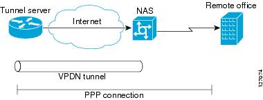
Dial-Out VPDN Scenario
In an L2TP dial-out deployment, the tunnel server receives PPP packets from it's local network to send to a remote network or device. The tunnel server initiates establishment of an L2TP tunnel with the NAS, and the NAS terminates the tunnel. The NAS must then establish a connection to the client.
L2TP Security for the Protection of VPDN Tunnels
L2TP security provides enhanced security for tunneled PPP frames by allowing the robust security features of IP Security (IPSec) to protect the L2TP VPDN tunnel and the PPP sessions within the tunnel. Without L2TP security, only a one-time, optional mutual authentication is performed during tunnel setup, with no authentication of subsequent data packets or control messages.
The deployment of Microsoft Windows 2000 demands the integration of IPSec with L2TP because this is the default VPDN networking scenario. This integration of protocols is also used for LAN-to-LAN VPDN connections in Microsoft Windows 2000. L2TP security provides integration of IPSec with L2TP in a solution that is scalable to large networks with minimal configuration.
The enhanced protection provided by L2TP security increases the integrity and confidentiality of tunneled PPP sessions within a standardized, well-deployed Layer 2 tunneling solution. The security features of IPSec and Internet Key Exchange (IKE) include confidentiality, integrity checking, replay protection, authentication, and key management. Traditional routing protocols such as Routing Information Protocol (RIP), Open Shortest Path First (OSPF), and Interior Gateway Routing Protocol (IGRP) will run transparently because a real PPP interface is associated with the secure tunnel. Additional benefits include built in keepalives and standardized interfaces for user authentication and accounting to authentication, authorization, and accounting (AAA) servers, interface statistics, standardized MIBs, and multiprotocol support.
VPDN Template
Beginning in Cisco IOS Release 12.2(8)T, a VPDN template can be configured with global default values that will supersede the system default values. These global default values are applied to all VPDN groups, unless specific values are configured for individual VPDN groups.
Beginning in Cisco IOS Release 12.2(13)T and Cisco IOS Release 12.2(28)SB, multiple named VPDN templates can be configured in addition to a single global (unnamed) VPDN template. A VPDN group can be associated with only one VPDN template.
Values configured in the global VPDN template are applied to all VPDN groups by default. A VPDN group can be disassociated from the global VPDN template, or associated with a named VPDN template. Associating a VPDN group with a named VPDN template automatically disassociates it from the global VPDN template.
The default hierarchy for the application of VPDN parameters to a VPDN group is as follows:
•
•
•
Individual VPDN groups can be disassociated from the associated VPDN template if desired, allowing the system default settings to be used for any parameters not configured in that individual VPDN group.
VPDN Source IP Address
A tunnel endpoint can be configured with a source IP address that is different from the IP address used to open the VPDN tunnel. When a source IP address is configured on a tunnel endpoint, the router will generate VPDN packets labeled with the configured source IP address. A source IP address may need to be configured if the tunnel endpoints are managed by different companies and addressing requirements necessitate that a particular IP address be used.
The source IP address can be configured globally, or for an individual VPDN group. The VPDN group configuration will take precedence over the global configuration.
VRF-Aware VPDN Tunnels
Prior to Cisco IOS Release 12.2(15)T or Cisco IOS Release 12.2(28)SB, you had to specify IP addresses from the global routing table for the endpoints of a VPDN tunnel. VRF-aware VPDN tunnels provide support for VPDN tunnels that terminate on a virtual private network (VPN) routing and forwarding instance (VRF) by allowing you to use IP addresses from a VRF routing table.
VRF-aware VPDN tunnels enhance the support of VPDN tunnels by allowing VPDN tunnels to start outside a Multiprotocol Label Switching (MPLS) VPN and terminate within the MPLS VPN. For example, this feature allows you to use a VRF address from a customer VRF as the destination address.
You can use VRF-aware VPDN tunnels with multihop, dial-in, and dial-out VPDN tunneling scenarios. In a multihop scenario, this feature is sometimes referred to as VRF-aware VPDN multihop.
MTU Tuning for L2TP VPDN Tunnels
Fragmentation and reassembly of packets is done at the process level in Cisco IOS software. When a tunnel server is aggregating large numbers of sessions and traffic flows, process switching can dramatically reduce performance. For this reason, it is highly desirable to reduce or eliminate the need for packet fragmentation and reassembly in a VPDN deployment, and instead move the burden of any required packet reassembly to the client devices.
Packets are fragmented when they attempt to pass through an egress interface with a maximum transmission unit (MTU) that is smaller than the size of the packet. By default, the MTU of most interface is 1500 bytes. Because of this default MTU size, TCP segments are created with a default payload of 1460 bytes, allowing room for the 40 byte TCP/IP header. Because L2TP encapsulation adds 40 bytes of header information, tunneled packets will exceed the MTU of an interface if MTU tuning is not performed.
In order to reach its final destination, a packet may traverse multiple egress interfaces. The path MTU is defined as the smallest MTU of all of the interfaces that the packet must pass through.
A number of different methods are available to perform MTU tuning. Their end goal is to prevent fragmentation of packets after they have been encapsulated for tunneling. These methods take advantage of distinct mechanisms to accomplish this, as described in the following sections:
•
•
•
•
MTU Tuning Using IP MTU Adjustments
The IP MTU configuration controls the maximum size of a packet allowed to be encapsulated by a Layer 2 protocol. The IP MTU of an interface can be manually lowered to compensate for the size of the L2TP header if the path MTU is known.
A router can also be configured to automatically adjust the IP MTU of an interface to compensate for the size of the L2TP header. The automatic adjustment corrects for the size of the L2TP header based on the MTU of the egress interface of that device. This configuration is effective only in preventing fragmentation when the MTU of that interface is the same as the path MTU.
MTU Tuning Using Path MTU Discovery
If the path MTU between the NAS and the tunnel server is unknown, or if it changes, path MTU discovery (PMTUD) can be used to perform MTU tuning. PMTUD, introduced in Cisco IOS Release 12.2(4)T, uses the Don't Fragment (DF) bit in the IP header to dynamically discover the smallest MTU among all the interfaces along a routing path.
The source host initially assumes that the path MTU is the known MTU of the first egress interface, and sends all packets on that path with the DF bit in the IP header set. If any of the packets are too large to be forwarded without fragmentation by the interface of a device along the path, that device will discard the packet and return an Internet Control Message Protocol (ICMP) Destination Unreachable message to the source host. The ICMP Destination Unreachable message includes code 4, which means "fragmentation needed and DF set," and indicates the IP MTU of the interface that was unable to forward the packet without fragmentation. This information allows the source host to reduce the size of the packet before retransmission to allow it to fit through that interface.
Enabling PMTUD makes VPDN deployments vulnerable to Denial of Service (DoS) attacks that use crafted ICMP messages to set a connection's path MTU to an impractically low value. This will cause higher layer protocols to time out because of a very low throughput, even though the connection is still in the established state. This type of attack is classified as a throughput-reduction attack. For more information on throughput-reduction attacks against L2TP VPDN deployments, see the Security Advisory Crafted ICMP Messages Can Cause Denial of Service.
To protect against a throughput-reduction attack, a range of acceptable values for the path MTU can be specified. If the device receives an ICMP code 4 message that advertises a next-hop path MTU that falls outside the configured size range, the device will ignore the message.
PMTUD can be unreliable, and may fail when performed over the Internet because some routers or firewalls are configured to filter out all ICMP messages. When the source host does not receive an ICMP destination unreachable message from a device that is unable to forward a packet without fragmentation, it will not know to reduce the packet size. The source host will continue to retransmit the same large packet. Because the DF bit is set, these packets will be continually dropped because they exceed the path MTU, and the connection will stop responding.
MTU Tuning Using TCP MSS Advertising
Because PMTUD can be unreliable, an alternate method of performing MTU tuning was introduced in Cisco IOS 12.2(4)T. This method of MTU tuning takes advantage of TCP Maximum Segment Size (MSS) advertisements in the incoming and outgoing synchronize (SYN) packets sent by the end hosts.
The TCP MSS defines the maximum amount of data that a host is willing to accept in a single TCP/IP datagram. The MSS value is sent as a TCP header option only in TCP SYN segments. Each side of a TCP connection reports its MSS value to the other side. The sending host is required to limit the size of data in a single TCP segment to a value less than or equal to the MSS reported by the receiving host.
If you configure a lower TCP MSS than the usual default of 1460, the size of TCP segments will be reduced to compensate for the information added by the L2TP header.
MTU Tuning Using PPP MRU Advertising
Another option for reducing fragmentation in an L2TP VPDN network requires that Maximum Receive Unit (MRU) negotiation is supported by the PPP client. One known client which supports MRU negotiations is the Windows XP PPP client. Unfortunately, other commonly deployed PPP clients do not adhere to the advertised PPP MRU as they should. Refer to the PPP client documentation to determine if your PPP client properly responds to the advertised PPP MRU.
PPP MRU allows a peer to advertise its maximum receive unit, which is derived from the MTU configuration on the virtual template interface. A device will not process a PPP frame with a payload larger than its advertised MRU. The Cisco PPP implementation uses the MTU of the interface as the advertised MRU value during PPP negotiations.
The MTU of a virtual template interface can be manually lowered to compensate for the size of the L2TP header. If the PPP peer listens to the MRU advertised during PPP negotiation, it will adjust its MTU (and indirectly its IP MTU) for that PPP link. This in turn will modify the TCP MSS that the peer advertises when opening up TCP connections.
Because the default MTU for an interface is 1500 bytes, the default MRU is 1500 bytes. Setting the MTU of an interface to 1460 changes the advertised MRU to 1460. This configuration would tell the peer to allow room for a 40-byte L2TP header.
One issue with lowering the MTU on the virtual-template interface is that the IP MTU is automatically lowered as well. It is not possible to configure an IP MTU greater than the MTU on a virtual template interface. This can be an issue if there is a mixture of peer devices that do and do not adjust their MTU based on the advertised MRU. The clients that are unable to listen to MRU advertisements and adjust accordingly will continue to send full-sized packets to the peer. Packets that are larger than the lowered IP MTU, yet smaller than the normal default IP MTU, will be forced to fragment. For example, an L2TP packet that is 1490 bytes would normally be transmitted without fragmentation. If the MTU has been lowered to 1460 bytes, this packet will be unnecessarily fragmented. In this situation, it would be optimal to advertise a lower MRU to those clients that are capable of listening and adjusting, yet still allow full-sized packets for those clients that are unable to adjust.
Clients that ignore the advertised MRU may experience the PMTUD problems described in the "MTU Tuning Using IP MTU Adjustments" section. PMTUD can be turned off by clearing the DF bit on the inner IP packet.
QoS for VPDN Tunnels
Quality of service (QoS) packet classification features provide the capability to partition network traffic into multiple priority levels or classes of service. Packet classifications provide the information required to coordinate QoS from end to end within and between networks. Packet classifications are used by other QoS features to assign the appropriate traffic handling policies, including congestion management, bandwidth allocation, and delay bounds for each traffic class.
For further information on QoS and traffic handling policies, refer to the Cisco IOS Quality of Service Solutions Configuration Guide, Release 12.4.
Packets can be marked for end-to-end QoS using the type of service (ToS) byte in the IP header. The first three bits of the ToS byte are used for IP precedence settings. Four of the remaining five bits are used to set the ToS. The remaining bit of the ToS byte is unassigned.
In a VPDN deployment, IP packets may be classified by an external source such as the customer network or a downstream client. By default, a tunnel endpoint will set the ToS byte in the Layer 2 header to zero, specifying normal service. Depending on the VPDN deployment, you may choose to configure your VPDN network to do one of the following in regard to QoS classifications:
•
•
•
The following sections provide additional information on QoS options for VPDN deployments:
•
•
•
QoS Classification Preservation
When Layer 2 packets are created the ToS byte value is set to zero by default, indicating normal service. This setting ignores the values of the ToS byte of the encapsulated IP packets that are being tunneled. The tunnel server can be configured to copy the contents of the ToS field of the inner IP packets to the ToS byte of the Layer 2 header. Copying the ToS field from the IP header to the Layer 2 header preserves end-to-end QoS for tunneled packets.
IP Precedence for VPDN Tunnels
IP precedence settings mark the class of service (CoS) for a packet. The three precedence bits in the ToS field of the IP header can be used to define up to six classes of service. If you choose to manually configure a specific IP precedence value for Layer 2 packets, QoS will not be preserved end-to-end across the tunnel.
ToS Classification for VPDN Tunnels
The ToS bits mark the ToS classification for a packet. Each of the four bits controls a particular aspect of the ToS—reliability, throughput, delay, and cost. If you choose to manually configure a specific ToS value for Layer 2 packets, QoS will not be preserved end-to-end across the tunnel.
How to Configure Additional VPDN Features
This section contains the following configuration tasks, which may be configured in any order:
•
•
•
•
•
•
•
•
•
•
Configuring a Dial-Out L2TP VPDN
Configuring a dial-out VPDN enables a tunnel server to send outbound calls over a VPDN tunnel using L2TP as the tunneling protocol. Dial-out VPDN configuration allows a centralized network to efficiently and inexpensively establish a virtual point-to-point connection with any number of remote offices.
Cisco routers can carry both dial-in and dial-out calls in the same L2TP tunnels.
The following sections contain additional information about L2TP dial-out configurations:
•
•
•
•
The following tasks must be completed to configure a dial-out L2TP VPDN:
•
•
•
•
L2TP Dial-Out Connection Establishment
Figure 24 shows the steps involved in establishing a dial-out connection for a typical dial-out scenario.
Figure 24
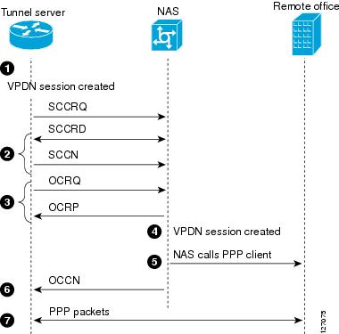
L2TP Dial-Out Process
The following sequence of events occurs during session establishment, and is keyed to Figure 24:
1.
The dialer issues a dial call request to the VPDN group, and the tunnel server creates a virtual access interface. If the dialer is a dialer profile, this interface becomes a member of the dial pool. If the dialer is DDR, the interface becomes a member of the rotary group.
The VPDN group creates a VPDN session for this connection and sets it in the pending state.
2.
3.
If the resource is available, the NAS responds to the tunnel server with an Outgoing Call Reply (OCRP) packet. If the resource is not available, the NAS responds with a Call Disconnect Notification (CDN) packet, and the session is terminated.
4.
5.
6.
7.
If the dialer interface is a DDR and a virtual profile is configured, the PPP endpoint is the tunnel server virtual access interface, not the dialer. All Layer 3 routes point to this interface instead of to the dialer.
L2TP Dial-Out Load Balancing and Redundancy
In Cisco IOS software prior to Release 12.2(15)T or 12.2(28)SB, load balancing and redundancy for dial-out VPDNs could be configured only with L2TP large-scale dial-out (LSDO) using Stack Group Bidding Protocol (SGBP). This method of load balancing and redundancy requires that the primary NAS is up and running for dial-out to take place, because the IP address of only that NAS is configured on the tunnel server. When the primary NAS is down, no dial-out can take place. When the primary NAS is up, the NAS determines among itself and the secondary NASs which NAS has the least congestion, and then inform the tunnel server to use the selected NAS for dial-out. Because the tunnel server cannot contact any other NASs when the primary NAS is down, failover is not supported for dial-out calls by this mechanism. For more information about configuring LSDO, refer to the chapter "Configuring Large-Scale Dial-Out" in the Cisco IOS Dial Technologies Configuration Guide, Release 12.4.
The ability to configure a tunnel server with the IP addresses of multiple NASs was introduced in Cisco IOS Release 12.2(15)T and Cisco IOS Release 12.2(28)SB. Load balancing, redundancy, and failover can all be controlled by assigning each NAS the desired priority settings on the tunnel server. Load balancing occurs between NASs with identical priority settings. When NASs are assigned different priority settings, if the NAS with the highest priority goes down the tunnel server will fail over to a lower priority NAS.
Prerequisites for Configuring a Dial-Out L2TP VPDN
Before performing these tasks, you should configure the required tasks in the "Configuring AAA for VPDNs" module.
Restrictions for Configuring a Dial-Out L2TP VPDN
•
•
•
•
Configuring the Tunnel Server to Request Dial-Out
The tunnel server must be configured to request the establishment of a VPDN tunnel with the NAS when it is directed to tunnel outbound PPP data. The VPDN group is linked to the dialer profile by the dialer pool number.
Perform this task to configure the tunnel server to request the establishment of a dial-out VPDN tunnel and to specify the dialer rotary group or dialer pool that may issue dial requests to the VPDN group.
SUMMARY STEPS
1.
2.
3.
4.
5.
6.
7.
8.
9.
DETAILED STEPS
Step 1
enable
Example:Router> enable
Enables privileged EXEC mode.
•
Step 2
configure terminal
Example:Router# configure terminal
Enters global configuration mode.
Step 3
Router(config)# vpdn-group 1
Creates a VPDN group and enters VPDN group configuration mode.
Step 4
Router(config-vpdn)# description myvpdngroup
(Optional) Adds a description to a VPDN group.
Step 5
request-dialout
Example:Router(config-vpdn)# request-dialout
Creates a request dial-out VPDN subgroup that configures a tunnel server to request the establishment of dial-out L2TP tunnels to a NAS and enters request dial-out VPDN subgroup configuration mode.
Step 6
protocol l2tp
Example:Router(config-vpdn-req-ou)# protocol l2tp
Specifies L2TP as the Layer 2 protocol that the VPDN group will use.
Step 7
pool-member pool-number
Example:Router(config-vpdn-req-ou)# pool-member 1
Assigns a request-dialout VPDN group to a dialer pool.
Step 8
exit
Example:Router(config-vpdn-req-ou)# exit
Exits request dial-out VPDN subgroup configuration mode.
Step 9
initiate-to ip ip-address [limit limit-number] [priority priority-number]
Example:Router(config-vpdn)# initiate-to ip 10.0.58.201 limit 5 priority 1
Specifies the IP address that will be used for Layer 2 tunneling.
•
–
–
Note
What to Do Next
•
•
Configuring the Dialer on the Tunnel Server
A request to tunnel outbound data from the tunnel server must be associated with a dialer profile.
Perform this task to configure the dialer profile on the tunnel server. A dialer profile must be configured for each dial-out destination.
SUMMARY STEPS
1.
2.
3.
4.
5.
6.
7.
8.
9.
10.
11.
DETAILED STEPS
What to Do Next
You must perform the task in the "Configuring the NAS to Accept Dial-Out" section.
Configuring the NAS to Accept Dial-Out
The NAS must be configured to accept outbound tunnels from the tunnel server, and to initiate PPP calls to the destination client. Outbound calls will be placed using the dialer interface specified in the VPDN group configuration.
Perform this task to configure the NAS to accept tunneled dial-out connections from the tunnel server. If multiple NASs are configured on the tunnel server, perform this task on each NAS.
SUMMARY STEPS
1.
2.
3.
4.
5.
6.
7.
8.
9.
10.
11.
DETAILED STEPS
What to Do Next
You must perform the task in the "Configuring the Dialer on the NAS" section.
Configuring the Dialer on the NAS
When the NAS receives outbound data from the tunnel server, it must initiate a PPP call to the destination client. The dialer used to initiate calls is specified in the VPDN group configuration, and must match the dialer rotary group number.
Perform this task to configure the dialer on the NAS for dial-out VPDN.
SUMMARY STEPS
1.
2.
3.
4.
5.
6.
7.
8.
9.
DETAILED STEPS
What to Do Next
You may perform any of the relevant optional tasks in this module or the "VPDN Tunnel Management" module.
Configuring L2TP Security for VPDN Tunnels
L2TP security provides enhanced security for tunneled PPP frames between the NAS and the tunnel server, increasing the integrity and confidentiality of tunneled PPP sessions within a standardized, well-deployed Layer 2 tunneling solution. The security features of IPSec and IKE include confidentiality, integrity checking, replay protection, authentication, and key management. Additional benefits include built-in keepalives and standardized interfaces for user authentication and accounting to AAA servers, interface statistics, standardized MIBs, and multiprotocol support.
L2TP security can be configured for both NAS-initiated L2TP tunneling scenarios and client-initiated L2TP tunneling scenarios.
The following sections contain additional information about L2TP security:
•
•
•
To configure L2TP security for VPDN tunnels, perform the following tasks:
•
•
L2TP Security with NAS-Initiated VPDN Tunnels
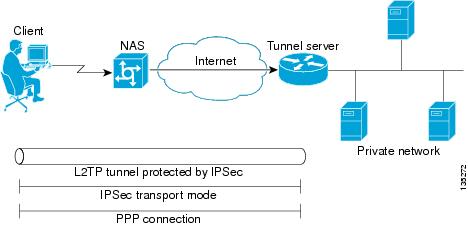
L2TP security can be configured to protect VPDN tunnels between the NAS and the tunnel server in NAS-initiated VPDN deployments. A NAS-initiated tunneling scenario with L2TP security protection is depicted in Figure 25.
Figure 25 L2TP Security for a NAS-Initiated Tunneling
Scenario
The client connects to the NAS through a medium that supports PPP, such as a dialup modem, digital subscriber line (DSL), ISDN, or a cable modem. If the connection from the client to the NAS is considered secure—such as a modem, ISDN, or a DSL connection—the client may choose not to provide additional security. The PPP session is securely tunneled from the NAS to the tunnel server without any required knowledge or interaction by the client. L2TP security protects the L2TP tunnel between the NAS and the tunnel server with IPSec.
L2TP Security with Client-Initiated VPDN Tunnels
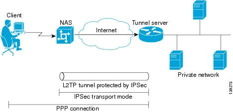
L2TP security can be configured to protect VPDN tunnels between the client and the tunnel server in client-initiated VPDN deployments. A client-initiated tunneling scenario with L2TP security protection is depicted in Figure 26.
Figure 26 L2TP Security for a Client-Initiated
Tunneling Scenario
The client initiates an L2TP tunnel to the tunnel server without the intermediate NAS participating in tunnel negotiation or establishment. The client must manage the software that initiates the tunnel. Microsoft Windows 2000 supports this VPDN scenario. In this scenario, extended services processor (ESP) with authentication must always be used. L2TP security protects the L2TP tunnel between the client and the tunnel server with IPSec.
Prerequisites for L2TP Security
•
•
•
NAS-Initiated Tunnels
•
Client-Initiated Tunnels
•
•
•
Configuring IPSec Protection of an L2TP Tunnel
Perform this task to configure IPSec protection of an L2TP tunnel:
•
•
SUMMARY STEPS
1.
2.
3.
4.
DETAILED STEPS
What to Do Next
You must perform the task in the "Creating the Security Profile" section.
Creating the Security Profile
A security profile must be configured to provide IPSec protection of L2TP tunnels. Perform this task to create the security profile:
•
•
Prerequisites
To create an IKE policy and a crypto profile configuration associated with the VPDN group, you must first configure phase 1 Internet Security Association and Key Management Protocol (ISAKMP) policy and an IPSec transform set. For information on configuring phase 1 ISAKMP policies and IPSec transform sets, refer to the Cisco IOS Security Configuration Guide, Release 12.4.
SUMMARY STEPS
1.
2.
3.
4.
5.
6.
7.
DETAILED STEPS
What to Do Next
You may perform the optional task in the "Verifying IPSec Protection of L2TP VPDN Tunnels" section.
Verifying IPSec Protection of L2TP VPDN Tunnels
Perform the tasks in this section to verify that L2TP tunnels are protected by IPSec.
•
•
•
Verifying Establishment of the Crypto Socket
Perform this task on the NAS or the tunnel server to verify that the crypto socket is created and activated in response to VPDN tunneling events.
SUMMARY STEPS
1.
2.
3.
DETAILED STEPS
Step 1
Enter this command to enable privileged EXEC mode. Enter your password if prompted:
Router> enableStep 2
Enter this command to turn on debug messages for socket messages:
Router# debug crypto socketStep 3
Enter this command to turn on debug messages for protocol-specific VPDN tunneling events. Examine the debug messages to verify that the socket is created and moved to the active state in response to L2TP tunnel events. The example shows debug output from successful crypto socket creation and activation:
Router# debug vpdn l2x-events*Mar 1 00:56:46.959:CRYPTO_SS(L2X Security):Passive open, socket info:local 10.0.0.13/1701, remote 10.0.0.12/1701, prot 17, ifc Fa0/0*Mar 1 00:56:47.291:L2TP:I SCCRQ from user02 tnl 5107*Mar 1 00:56:47.295:L2X:Requested security for socket, UDP socket info:local 10.0.0.13(1701), remote 10.0.0.12(1701)*Mar 1 00:56:47.295:Tnl 13582 L2TP:Got a challenge in SCCRQ, user02*Mar 1 00:56:47.295:Tnl 13582 L2TP:New tunnel created for remote user02, address 10.0.0.12*Mar 1 00:56:47.295:Tnl 13582 L2TP:O SCCRP to user02 tnlid 5107*Mar 1 00:56:47.295:Tnl 13582 L2TP:Control channel retransmit delay set to 1 seconds*Mar 1 00:56:47.299:Tnl 13582 L2TP:Tunnel state change from idle to wait-ctl-reply*Mar 1 00:56:47.299:CRYPTO_SS(L2X Security):Completed binding of application to socket
Verifying the Crypto Map Configuration
Perform this task to verify that the crypto map was dynamically created for the L2TP tunnel.
SUMMARY STEPS
1.
2.
DETAILED STEPS
Step 1
Enter this command to enable privileged EXEC mode. Enter your password if prompted:
Router> enableStep 2
Enter this command to display information about a crypto map. Ensure that the proper interface is using the correct crypto map. The following example displays output for the crypto map with the name l2tpsec and shows that it is being used by the FastEthernet 0/0 interface:
Router# show crypto map tag l2tpsecCrypto Map "l2tpsec" 10 ipsec-isakmpNo matching address list set.Current peer:0.0.0.0Security association lifetime:4608000 kilobytes/3600 secondsPFS (Y/N):NTransform sets={ esp, }Crypto Map "l2tpsec" 20 ipsec-isakmpPeer = 10.0.0.13Extended IP access listaccess-list permit udp host 10.0.0.12 port = 1701 host 10.0.0.13 port = 1701Current peer:10.0.0.13Security association lifetime:4608000 kilobytes/3600 secondsPFS (Y/N):NTransform sets={ esp, }!The output below shows that the interface FastEthernet0/0 is uing the crypto map named !l2tpsec.Interfaces using crypto map l2tpsec:FastEthernet0/0
Verifying Encryption and Decryption of L2TP Packets
Perform this task to verify that L2TP packets are being encrypted and decrypted.
SUMMARY STEPS
1.
2.
DETAILED STEPS
Step 1
Enter this command to enable privileged EXEC mode. Enter your password if prompted:
Router> enableStep 2
Enter this command to display information about active crypto engine connections. The number of encryption and decryption events are displayed.
Router# show crypto engine connections activeID Interface IP-Address State Algorithm Encrypt Decrypt1 FastEthernet0/0 10.0.0.13 set HMAC_SHA+DES_56_CB 0 02000 FastEthernet0/0 10.0.0.13 set HMAC_SHA+DES_56_CB 0 622001 FastEthernet0/0 10.0.0.13 set HMAC_SHA+DES_56_CB 64 0
What to Do Next
You may perform any of the relevant optional tasks in this module or the "VPDN Tunnel Management" module.
Creating a VPDN Template
Beginning in Cisco IOS Release 12.2(8)T, a VPDN template can be configured with global default values that will supersede the system default values. These global default values are applied to all VPDN groups, unless specific values are configured for individual VPDN groups.
Beginning in Cisco IOS Release 12.2(13)T and Cisco IOS Release 12.2(28)SB, multiple named VPDN templates can be configured in addition to a single global (unnamed) VPDN template. A VPDN group can be associated with only one VPDN template.
Values configured in the global VPDN template are applied to all VPDN groups by default. A VPDN group can be disassociated from the global VPDN template, or associated with a named VPDN template. Associating a VPDN group with a named VPDN template automatically disassociates it from the global VPDN template. If you remove a named VPDN template configuration, all VPDN groups that were associated with it will automatically be associated with the global VPDN template.
The hierarchy for the application of VPDN parameters to a VPDN group is as follows:
•
•
•
Perform this task on the NAS or the tunnel server to create a VPDN template.
Prerequisites
•
•
Restrictions
•
•
SUMMARY STEPS
1.
2.
3.
DETAILED STEPS
What to Do Next
•
•
•
•
Associating a VPDN Group with a VPDN Template
VPDN groups are associated with the global VPDN template by default. Individual VPDN groups can be associated with a named VPDN template instead. Associating a VPDN group with a named VPDN template disassociates the VPDN group from the global VPDN template.
Perform this task on the NAS or the tunnel server to associate a specific VPDN group with a named VPDN template, or to reassociate a VPDN group with the global VPDN template if it has been previously disassociated from the global VPDN template.
Prerequisites
•
•
SUMMARY STEPS
1.
2.
3.
4.
DETAILED STEPS
What to Do Next
•
•
Disassociating a VPDN Group from the VPDN Template
Individual VPDN groups can be disassociated from the VPDN template if desired, allowing the system default settings to be used for any parameters not configured in the individual VPDN group.
Perform this task on the NAS or the tunnel server to disassociate a specific VPDN group from any VPDN template.
Prerequisites
You must be running Cisco IOS Release 12.2(8)T, Cisco IOS Release 12.2(28)SB, or a later release.
SUMMARY STEPS
1.
2.
3.
4.
DETAILED STEPS
What to Do Next
You may perform any of the relevant optional tasks in this module or the "VPDN Tunnel Management" module.
Configuring the VPDN Source IP Address
A tunnel endpoint can be configured with a source IP address that is different from the IP address used to open the VPDN tunnel. When a source IP address is configured on a tunnel endpoint, the router will generate VPDN packets labeled with the configured source IP address. Setting a source IP address may be required if the tunnel endpoints are managed by different companies and addressing requirements necessitate that a particular IP address be used.
The source IP address can be configured globally, or for individual VPDN groups. The VPDN group configuration will take precedence over the global configuration.
Perform one of the following tasks to configure a source IP address on a NAS or a tunnel server:
•
•
Configuring the Global VPDN Source IP Address
You may configure a single global source IP address on a device. If a source IP address is configured for a VPDN group, the global source IP address will not be used for tunnels belonging to that VPDN group.
Perform this task on a tunnel endpoint to configure the global source IP address.
SUMMARY STEPS
1.
2.
3.
DETAILED STEPS
What to Do Next
•
•
Configuring the Source IP Address for a VPDN Group
You may configure a source IP address for a specific VPDN group. If a source IP address is configured for a VPDN group, the global source IP address will not be used for tunnels belonging to that VPDN group.
Perform this task on a tunnel endpoint to configure a source IP address for a specific VPDN group.
SUMMARY STEPS
1.
2.
3.
4.
DETAILED STEPS
What to Do Next
•
•
Configuring VRF-Aware VPDN Tunneling
Prior to Cisco IOS Release 12.2(15)T and Cisco IOS Release 12.2(28)SB, you had to specify IP addresses from the global routing table for the endpoints of a VPDN tunnel. VRF-aware VPDN tunnels support VPDN tunnels that terminate on a VRF by allowing you to use IP addresses from a VRF routing table.
VRF-aware VPDN tunneling enhances the support of L2TP VPDNs by allowing VPDN tunnels to start outside an MPLS VPN and terminate within the MPLS VPN. For example, this feature allows you to use a VRF address from a customer VRF as the destination address.
For more information on remote access to MPLS VPNs, refer to the "Overview of Dial Access to MPLS VPN Integration" chapter of the Cisco Remote Access to MPLS VPN Solution Overview and Provisioning Guide, Release 2.0.
You can use VRF-aware VPDN tunnels with multihop, dial-in, and dial-out L2TP VPDN tunneling scenarios. In a multihop scenario, this feature is sometimes referred to as VRF-aware VPDN multihop.
VRF-aware VPDN tunneling can be configured locally on a NAS, tunnel server, or multihop tunnel switch, or it can be configured in the remote RADIUS server profile. Configuring VRF-aware VPDN tunneling in the RADIUS server profile will propagate the configuration only to a NAS or multihop tunnel switch. To configure VRF-aware VPDN tunnels on a tunnel server, you must configure the tunnel server locally.
Perform one of the following tasks to configure a VRF-aware VPDN tunnel:
•
•
Configuring VRF-Aware VPDN Tunneling Locally
VRF-aware VPDN tunneling can be configured locally on a NAS, a tunnel server, or a multihop tunnel switch. Configuring VRF-aware VPDN tunneling on a device specifies that the tunnel endpoint IP addresses configured for that VPDN group belong to the specified VRF routing table rather than the global routing table.
Perform this task on the multihop tunnel switch, the NAS, or the tunnel server to configure a VPDN tunnel to belong to a VRF.
Prerequisites
•
•
•
•
Restrictions
L2TP is the only tunneling protocol supported for VRF-aware VPDN tunneling.
SUMMARY STEPS
1.
2.
3.
4.
DETAILED STEPS
What to Do Next
You may perform any of the relevant optional tasks in this module or the "VPDN Tunnel Management" module.
Configuring VRF-Aware VPDN Tunneling on the Remote RADIUS AAA Server
VRF-aware VPDN tunneling can be configured in the remote RADIUS server profile. Configuring VRF-aware VPDN tunneling on a device specifies that the tunnel endpoint IP addresses configured for that VPDN group belong to the specified VRF routing table rather than the global routing table.
Configuring VRF-aware VPDN tunneling in the RADIUS server profile will propagate the configuration only to a NAS or multihop tunnel switch. To configure VRF-aware VPDN tunnels on a tunnel server, you must configure the tunnel server locally by performing the task in the "Configuring VRF-Aware VPDN Tunneling Locally" section.
Perform this task on the remote RADIUS server. The tunnel attributes configured in the RADIUS server profile will be propagated to the NAS or multihop tunnel switch.
Prerequisites
•
•
•
•
•
•
Restrictions
L2TP is the only tunneling protocol supported for VRF-aware VPDN tunneling.
SUMMARY STEPS
1.
2.
3.
or
Cisco-Avpair = vpdn:vpn-id=vpn-id4.
DETAILED STEPS
What to Do Next
You may perform any of the relevant optional tasks in this module or the "VPDN Tunnel Management" module.
Performing MTU Tuning for L2TP VPDNs
MTU tuning reduces or prevents packet fragmentation and reassembly of L2TP packets in a VPDN deployment. Because the tunnel server is typically the device that aggregates large numbers of sessions and traffic flows in a VPDN deployment, the performance impact of the process switching required for packet fragmentation and reassembly is most dramatic, and least desirable, on this device.
A number of different methods are available to perform MTU tuning. The goal is to prevent fragmentation of packets after they have been encapsulated for tunneling. In Cisco IOS Release 12.2(4)T and later releases, the most reliable method of MTU tuning is manually configuring the advertised TCP MSS.
Perform one of the following tasks to perform MTU tuning:
•
•
•
•
•
Manually Configuring the IP MTU for VPDN Deployments
One method for reducing the amount of fragmentation of tunneled packets is to manually configure the IP MTU to the largest IP packet size that will not exceed the path MTU between the NAS and the tunnel server once the full Layer 2 header is added to the packet.
Perform this task on the tunnel server to lower the IP MTU manually.
Prerequisites
•
•
SUMMARY STEPS
1.
2.
3.
4.
DETAILED STEPS
What to Do Next
You may perform any of the relevant optional tasks in this module or the "VPDN Tunnel Management" module.
Enabling Automatic Adjustment of the IP MTU for VPDN Deployments
A tunnel server can be configured to automatically adjust the IP MTU of an interface to compensate for the size of the Layer 2 header. The automatic adjustment corrects for the size of the Layer 2 header based on the MTU of the egress interface of that device. This configuration is effective in preventing fragmentation only when the MTU of that interface is the same as that of the path MTU.
Perform this task on the tunnel server to enable automatic adjustment of the IP MTU.
Prerequisites
•
•
Restrictions
•
•
•
•
SUMMARY STEPS
1.
2.
3.
4.
DETAILED STEPS
What to Do Next
You may perform any of the relevant optional tasks in this module or the "VPDN Tunnel Management" module.
Enabling Path MTU Discovery for VPDNs
If the path MTU between the NAS and the tunnel server is variable or unknown, PMTUD can be enabled for VPDNs. PMTUD uses the DF bit in the IP header to dynamically discover the smallest MTU among all the interfaces along a routing path.
When PMTUD is enabled, VPDN deployments are vulnerable to DoS attacks that use crafted ICMP messages to set a connection's path MTU to an impractically low value. This will cause higher layer protocols to time out because of a very low throughput, even though the connection is still in the established state. This type of attack is classified as a throughput-reduction attack.
To protect against a throughput-reduction attack, configure a range of acceptable values for the path MTU. If the device receives an ICMP message that advertises a next-hop path MTU that falls outside the configured size range, the device will ignore the message.
For more information on throughput-reduction attacks and for information on detecting a PMTUD attack on an L2TP VPDN deployment, see the Cisco Security Advisory Crafted ICMP Messages Can Cause Denial of Service.
PMTUD may fail when performed over the Internet, because some routers or firewalls are configured to filter out all ICMP messages. When the source host does not receive an ICMP Destination Unreachable message from a device that is unable to forward a packet without fragmentation, it will not know to reduce the packet size. The source host will continue to retransmit the same large packet. Because the DF bit is set, these packets will be continually dropped because they exceed the path MTU, and the connection will stop responding entirely.
Perform this task on the tunnel server to enable PMTUD and to protect the L2TP VPDN deployment against throughput-reduction DoS attacks.
Prerequisites
•
•
•
•
–
–
–
For a complete list of Cisco IOS software rebuild releases that support the vpdn pmtu command, refer to the Cisco Security Advisory Crafted ICMP Messages Can Cause Denial of Service.

Note
SUMMARY STEPS
1.
2.
3.
4.
5.
6.
7.
DETAILED STEPS
What to Do Next
You may perform any of the relevant optional tasks in this module or the "VPDN Tunnel Management" module.
Manually Configuring the Advertised TCP MSS
Manually configuring a lower value for the advertised TCP MSS reduces the size of IP packets created by TCP at the transport layer, reducing or eliminating the amount of packet fragmentation that will occur in a VPDN deployment.
The default advertised TCP MSS is 1460, which allows room for the 40-byte TCP/IP header. To prevent packet fragmentation over a tunnel, additionally reduce the TCP MSS to provide space for the Layer 2 encapsulation header.
Perform this task on the tunnel server to manually lower the TCP MSS.
Prerequisites
•
•
SUMMARY STEPS
1.
2.
3.
4.
DETAILED STEPS
What to Do Next
You may perform any of the relevant optional tasks in this module or the "VPDN Tunnel Management" module.
Configuring MRU Advertising
You can manually configure a lower MTU on the virtual template interface to compensate for the size of the Layer 2 header. The MTU of the interface is advertised to PPP peers as the MRU. If the peer is running a PPP client that is capable of listening to this advertisement, it can adjust its MTU (and indirectly its IP MTU) for that PPP link. This in turn modifies the TCP MSS that the peer advertises when opening up TCP connections.
Because the default MTU for an interface is 1500 bytes, the default MRU is 1500 bytes. Setting the MTU of an interface to 1460 changes the advertised MRU to 1460. This configuration would tell the peer to allow room for a 40-byte Layer 2 header.
Perform this task on the tunnel server to manually lower the MTU of the virtual template interface.
Prerequisites
•
•
Restrictions
•
•
•
•
SUMMARY STEPS
1.
2.
3.
4.
5.
6.
7.
DETAILED STEPS
What to Do Next
You may perform any of the relevant optional tasks in this module or the "VPDN Tunnel Management" module.
Configuring QoS Packet Classifications for VPDNs
QoS packet classification provides the capability to partition network traffic into multiple priority levels or classes of service. Packet classifications provide the information required to coordinate QoS from end to end within and between networks.
In a VPDN deployment, IP packets may be classified by an external source such as the customer network or a downstream client. By default, a tunnel endpoint will set the ToS byte in the Layer 2 header to zero, specifying normal service. Depending on the VPDN deployment, instead of using the default setting you may choose to configure your VPDN network to preserve QoS end to end by copying the contents of the ToS byte from the IP header to the Layer 2 header, or to manually configure custom packet classifications for the VPDN network.
QoS configurations are generally required only on the tunnel server, the device that must manage and prioritize large volumes of outbound traffic.
Perform the following task if you choose to preserve end-to-end QoS:
•
Perform either or both of these tasks to manually configure custom packet classifications for your VPDN deployment:
•
•
Configuring Preservation of QoS Classifications in the ToS Byte
When Layer 2 packets are created the ToS byte value is set to zero by default, indicating normal service. This setting ignores the values of the ToS byte of the encapsulated IP packets that are being tunneled. The tunnel server can be configured to copy the contents of the ToS field of the inner IP packets to the ToS byte of the Layer 2 header. Copying the ToS field from the IP header to the Layer 2 header preserves end-to-end QoS for tunneled packets.
Perform this task to configure a tunnel server to copy the ToS byte from the IP packet to the Layer 2 header.
Prerequisites
A VPDN deployment must be configured.
Restrictions
•
•
•
SUMMARY STEPS
1.
2.
3.
4.
DETAILED STEPS
What to Do Next
You may perform any of the relevant optional tasks in this module or the "VPDN Tunnel Management" module.
Manually Configuring the IP Precedence for VPDNs
IP precedence bits of the ToS byte can be manually configured to set a CoS for Layer 2 packets. If you choose to manually configure a specific IP precedence value for Layer 2 packets, QoS will not be preserved end to end across the tunnel.
Perform this task on the tunnel server to manually configure a CoS for Layer 2 packets.
Prerequisites
A VPDN deployment must be configured.
Restrictions
Manual configuration of an IP precedence value will override the configuration of the ip tos reflect command.
SUMMARY STEPS
1.
2.
3.
4.
DETAILED STEPS
What to Do Next
•
•
Manually Configuring the ToS for VPDN Sessions
The ToS bits can be manually configured to mark the ToS of a packet. If you choose to manually configure a specific ToS value for Layer 2 packets, QoS will not be preserved end-to-end across the tunnel.
Perform this task on the tunnel server to manually configure a CoS for Layer 2 packets.
Prerequisites
A VPDN deployment must be configured.
Restrictions
Manual configuration of a ToS value will override the configuration of the ip tos reflect command.
SUMMARY STEPS
1.
2.
3.
4.
DETAILED STEPS
What to Do Next
You may perform any of the relevant optional tasks in this module or the "VPDN Tunnel Management" module.
Configuration Examples for Additional VPDN Features
This section contains the following configuration examples:
•
•
•
•
•
•
•
•
•
•
•
•
•
•
•
•
•
•
•
•
•
Configuring a Basic Dial-Out VPDN: Examples
The following example enables VPDN, configures a tunnel server to request dial-out VPDN tunnels for outbound PPP calls, and configures the dialer interface to place outbound calls using the VPDN tunnel:
vpdn enablevpdn-group outrequest-dialoutprotocol l2tppool-member 1!initiate-to ip 10.10.10.1local name tunnelserver32
!interface dialer 1ip address 10.1.1.1 255.255.0encapsulation pppdialer remote-name router22dialer string 5550100dialer vpdndialer pool 1dialer-group 1ppp authentication chapThe following example enables VPDN, configures a NAS to accept dial-out VPDN tunnel requests, and configures a dialer interface on the NAS to place outbound calls to the PPP client:
vpdn enablevpdn-group 1accept-dialoutprotocol l2tpdialer 3
!terminate-from hostname tunnelserver32
!
interface dialer 3
ip unnumbered Ethernet0
encapsulation ppp
dialer in-band
dialer aaa
dialer-group 3
ppp authentication chap
Configuring L2TP Dial-Out Load Balancing: Example
The following example configures a preexisting dial-out VPDN group on a tunnel server to load balance calls across multiple NASs. Calls will be load balanced between the NASs because the same priority value has been assigned to each NAS with the initiate-to command:
vpdn-group 1initiate-to ip 10.0.58.201 priority 10initiate-to ip 10.0.58.205 priority 10initiate-to ip 10.0.58.207 priority 10initiate-to ip 10.0.58.209 priority 10Configuring L2TP Dial-Out Failover Redundancy: Example
The following example configures a preexisting dial-out VPDN group on a tunnel server for failover between multiple NASs. If the NAS with the highest priority goes down, the tunnel server will fail over to a NAS with a lower priority. The highest priority value you can assign is 1.
vpdn-group 1initiate-to ip 10.0.58.201 priority 1initiate-to ip 10.0.58.205 priority 10initiate-to ip 10.0.58.209 priority 15L2TP Dial-Out Failover Redundancy with Tunnel Timers: Example
The following example configures a preexisting dial-out VPDN group on a tunnel server for failover using custom L2TP tunnel timers. The tunnel server is configured to retry to connect to a NAS five times, with a minimum wait of 10 seconds between attempts. If the tunnel server is not able to connect to the highest priority NAS after the specified number of retries, failover to the next highest priority NAS will occur. The tunnel server will not attempt to recontact the highest priority NAS until 420 seconds have passed.
vpdn-group 1initiate-to ip 10.0.58.201 priority 1initiate-to ip 10.0.58.207 priority 50initiate-to ip 10.0.58.205 priority 100l2tp tunnel retransmit initial retries 5l2tp tunnel retransmit initial timeout min 10l2tp tunnel busy timeout 420Configuring IPSec Protection of a NAS-Initiated L2TP Tunnel: Example
The following example configures IPSec protection of L2TP tunnels on the NAS and the tunnel server for a NAS-initiated tunneling scenario:
NAS Configuration
! Passwords for the L2TP tunnel authenticationusername NAS password 0 ciscousername TS1 password 0 cisco!! VPDN configuration to tunnel users with the domain cisco.com to the LNS. This ! configuration has l2tp tunnel authentication enabled.!vpdn enablevpdn-group 1request-dialinprotocol l2tpdomain cisco.com!initiate-to ip 10.0.0.13local name NASl2tp security crypto-profile l2tp keep-sal2tp tunnel password cisco!crypto isakmp policy 1authentication pre-share!crypto isakmp key cisco address 10.0.0.13!crypto ipsec transform-set esp-des-sha-transport esp-des esp-sha-hmacmode transport!! Crypto profile configuration which is bound to the vpdn-group shown abovecrypto map l2tpsec 10 ipsec-isakmp profile l2tpset transform-set esp-des-sha-transport!interface FastEthernet0/0ip address 10.0.0.12 255.255.255.0crypto map l2tpsecTunnel Server Configuration
! PPP client username and password needed for CHAP authenticationusername userSerial10@cisco.com password 0 cisco!! Passwords for the L2TP tunnel authenticationusername NAS password 0 ciscousername TS1 password 0 cisco!! Using address pool to assign client an IP addressip address-pool local!! VPDN configurationvpdn enablevpdn-group 1accept-dialinprotocol anyvirtual-template 1!terminate-from hostname NASlcp renegotiation on-mismatchl2tp security crypto-profile l2tp keep-sa!crypto isakmp policy 1authentication pre-sharecrypto isakmp key cisco address 10.0.0.12!crypto ipsec transform-set esp-des-sha-transport esp-des esp-sha-hmacmode transport!crypto map l2tpsec 10 ipsec-isakmp profile l2tpset transform-set esp-des-sha-transport!interface FastEthernet0/0ip address 10.0.0.13 255.255.255.0speed 10half-duplexcrypto map l2tpsecConfiguring IPSec Protection of a Client-Initiated L2TP Tunnel: Example
The following example configures IPSec protection of L2TP tunnels on the tunnel server for a client-initiated tunneling scenario:
! PPP client username and password needed for CHAP authenticationusername userSerial10@cisco.com password 0 cisco! Passwords for the L2TP tunnel authentication.username NAS password 0 ciscousername TS1 password 0 cisco!! Using address pool to assign client an IP addressip address-pool local!! VPDN configurationvpdn enablevpdn-group dial-inaccept-dialinprotocol l2tpvirtual-template 1!l2tp security crypto-profile l2tpno l2tp tunnel authenticationip pmtu!crypto ipsec transform-set esp-des-sha-transport esp-des esp-sha-hmacmode transport!crypto map l2tpsec 10 ipsec-isakmp profile l2tpset transform-set esp-des-sha-transportset security-association lifetime seconds 120!interface FastEthernet0/0ip address 10.0.0.13 255.255.255.0speed 10half-duplexcrypto map l2tpsecConfiguring a Global VPDN Template: Example
The following example configures two VPDN parameters in the unnamed global VPDN template:
vpdn-templatelocal name host43ip tos reflectConfiguring a Named VPDN Template: Example
The following example configures two VPDN parameters in a VPDN template named l2tp. The named VPDN template is associated with the VPDN group named l2tp_tunnels.
vpdn-template l2tpl2tp tunnel busy timeout 65l2tp tunnel password tunnel4me!vpdn-group l2tp_tunnelssource vpdn-template l2tp_tunnelsDisassociating a VPDN Group from the VPDN Template: Example
The following example disassociates the VPDN group named l2f from the VPDN template. The system default settings will be used for all VPDN parameters that are not specified in the VPDN group configuration.
vpdn-group l2fno source vpdn-templateConfiguring a Global VPDN Source IP Address: Example
The following example configures a global source IP address. This source IP address will be used for all tunnels established on the router unless a specific source IP address is configured for a VPDN group.
vpdn source-ip 10.1.1.1Configuring a Source IP Address for a VPDN Group: Example
The following example configures a source IP address for tunnels associated with the VPDN group named tunneling. This source IP address will override any configured global source IP address for tunnels associated with this VPDN group.
vpdn-group tunnelingsource-ip 10.1.1.2Configuring VRF-Aware VPDN Tunnels Locally: Example
The following example configures a multihop tunnel switch to connect a NAS to a remote tunnel server within a VRF:
NAS
interface loopback 0ip address 172.16.45.6 255.255.255.255!vpdn enablevpdn-group group1request-dialinprotocol l2tpdomain cisco.com!initiate-to 10.10.104.9local name nas32source-ip 172.16.45.6l2tp tunnel password secret1Multihop Tunnel Switch
ip vrf cisco-vrfvpn id A1:3F6C!interface loopback 0ip address 10.10.104.22 255.255.255.255!interface loopback 40ip vrf forwarding cisco-vrfip address 172.16.40.241 255.255.255.255!vpdn enablevpdn multihop!vpdn-group mhopinaccept-dialinprotocol l2tpvirtual-template 4!terminate-from hostname nas32source-ip 10.10.104.9l2tp tunnel password secret1!vpdn-group mhopoutrequest-dialinprotocol l2tpdomain cisco.com!vpn vrf cisco-vrfinitiate-to ip 172.16.45.6source-ip 172.16.40.241local name multihop-tsw25l2tp tunnel password secret2Tunnel Server
interface loopback 0ip address 172.16.45.6 255.255.255.255!vpdn enablevpdn-group ciscoaccept-dialinprotocol l2tpvirtual-template 1!terminate-from hostname multihop-tsw25source-ip 172.16.45.6local name ts-12l2tp tunnel password secret2Configuring VRF-Aware VPDN Tunnels on the Remote RADIUS AAA Server: Examples
The following examples configure VRF-aware VPDN tunnels for a service provider network. The AAA RADIUS server user profile defines VPDN tunnel attributes, which can propagate to multiple NASs or tunnel switches.
RADIUS User Profile—VRF Name
The following example specifies that the source and destination IP addresses belong to the VPN named vpn-first:
cisco.com Password = "secret"Service-Type = Outbound-User,cisco-avpair = "vpdn:tunnel-id=LAC",cisco-avpair = "vpdn:tunnel-type=l2tp",cisco-avpair = "vpdn:ip-addresses=10.0.0.1",cisco-avpair = "vpdn:source-ip=10.0.0.9",cisco-avpair = "vpdn:vpn-vrf=vpn-first"cisco-avpair = "vpdn:l2tp-tunnel-password=supersecret"RADIUS User Profile—VRF ID
The following example specifies that the source and destination IP addresses belong to the VPN with the ID A1:3F6C:
cisco.com Password = "secret"Service-Type = Outbound-User,cisco-avpair = "vpdn:tunnel-id=LAC",cisco-avpair = "vpdn:tunnel-type=l2tp",cisco-avpair = "vpdn:ip-addresses=10.0.0.1",cisco-avpair = "vpdn:source-ip=10.0.0.9",cisco-avpair = "vpdn:vpn-id=A1:3F6C"cisco-avpair = "vpdn:l2tp-tunnel-password=supersecret"Manually Configuring the IP MTU for VPDN Deployments: Example
The following example manually configures an IP MTU of 1460 bytes for all tunnels that use the virtual-template named 1:
interface virtual-template 1ip mtu 1460Enabling Automatic Adjustment of the IP MTU for VPDN Deployments: Example
The following example configures tunnels associated with the VPDN group named tunneler to automatically adjust the IP MTU based on the MTU of the egress interface of the device:
vpdn-group tunnelerip mtu adjustEnabling Path MTU Discovery for VPDNs: Example
The following example enables PMTUD for the VPDN group named tunnelme and configures the device to accept path MTU values ranging from 576 to 1460 bytes. The device will ignore code 4 ICMP messages that specify a path MTU outside of this range.
vpdn-group tunnelmeip pmtu!vpdn pmtu maximum 1460vpdn pmtu minimum 576Manually Configuring the Advertised TCP MSS: Example
The following example manually configures a TCP MSS of 1420 bytes for all tunnels that use the virtual template named 2:
interface virtual-template 2ip tcp adjust-mss 1420Configuring MRU Advertising: Example
The following example manually configures an MTU of 1460 bytes for all tunnels that use the virtual template named 3. The VPDN group named mytunnels is configured to perform LCP renegotiation because it uses proxy LCP.
interface virtual-template 3mtu 1460!vpdn-group mytunnelslcp renegotiation alwaysConfiguring Preservation of QoS Classifications in the ToS Byte: Example
The following example configures preservation of the IP ToS field for an existing VPDN group named out1:
vpdn-group out1ip tos reflectManually Configuring the IP Precedence for VPDNs: Example
The following example manually configures an IP precedence value for an existing VPDN group named out2:
vpdn-group out2ip precedence priorityManually Configuring the ToS for VPDN Sessions: Example
The following example manually configures a ToS classification for an existing VPDN group named out3:
vpdn-group out3ip tos 9Where to Go Next
You may perform any of the relevant optional tasks in the "VPDN Tunnel Management" module.
Additional References
The following sections provide references related to additional L2TP VPDN features.
Related Documents
VPDN technology overview
VPDN commands: complete command syntax, command mode, defaults, usage guidelines, and examples
Cisco IOS VPDN Command Reference, Release 12.4T
Information about PPP configurations
"PPP Configuration" part of the Cisco IOS Dial Technologies Configuration Guide, Release 12.4
Dial Technologies commands: complete command syntax, command mode, defaults, usage guidelines, and examples
Cisco IOS Dial Technologies Command Reference, Release 12.4T
Information about IP application configurations
Cisco IOS IP Application Services Configuration Guide, Release 12.4
IP application commands: complete command syntax, command mode, defaults, usage guidelines, and examples
Cisco IOS IP Application Services Command Reference, Release 12.4
Information about MPLS VPNs
"Overview of Dial Access to MPLS VPN Integration" chapter of the Cisco Remote Access to MPLS VPN Solution Overview and Provisioning Guide, Release 2.0
Information about IPSec transform sets, crypto maps, and ISAKMP policies
"Implementing IPSec and IKE" part of the Cisco IOS Security Configuration Guide, Release 12.4
Security commands: complete command syntax, command mode, defaults, usage guidelines, and examples
Cisco IOS Security Command Reference, Release 12.4T
Information about QoS configurations
Cisco IOS Quality of Service Solutions Configuration Guide, Release 12.4
QoS commands: complete command syntax, command mode, defaults, usage guidelines, and examples
Cisco IOS Quality of Service Solutions Command Reference, Release 12.4T
Information on MTU tuning for L2TP tunneling deployments
Information on IP packet fragmentation and PMTUD
Information on throughput-reduction DoS attacks
Standards
MIBs
None
To locate and download MIBs for selected platforms, Cisco IOS releases, and feature sets, use Cisco MIB Locator found at the following URL:
RFCs
Technical Assistance
Feature Information for Additional VPDN Features
Table 10 lists the features in this module and provides links to specific configuration information. Only features that were introduced or modified in Cisco IOS Release 12.2(1) or a later release appear in the table.
Not all commands may be available in your Cisco IOS software release. For details on when support for a specific command was introduced, see the command reference documentation.
For information on a feature in this technology that is not documented here, see the "VPDN Features Roadmap."
Cisco IOS software images are specific to a Cisco IOS software release, a feature set, and a platform. Use Cisco Feature Navigator to find information about platform support and Cisco IOS software image support. Access Cisco Feature Navigator at http://www.cisco.com/go/fn. You must have an account on Cisco.com. If you do not have an account or have forgotten your username or password, click Cancel at the login dialog box and follow the instructions that appear.
Note
Table 10 Feature Information for Configuring Additional VPDN Features
L2TP Dial-Out Load Balancing and Redundancy
12.2(15)T
12.2(28)SBThis feature enables a tunnel server to dial out to multiple NASs. When the NAS with the highest priority goes down, it is possible for the tunnel server to fail over to another lower priority NAS. The tunnel server can also load balance sessions between multiple NASs that have the same priority settings.
The following sections provide information about this feature:
•
•
The following command was modified by this feature: initiate-to.
L2TP Security
12.2(4)T
12.2(28)SBThis feature allows the security features of IP Security (IPSec) to protect the L2TP tunnel and the PPP sessions within the tunnel. In addition, the L2TP Security feature provides built-in keepalives and standardized interfaces for user authentication and accounting to authentication, authorization, and accounting (AAA) servers.
The following sections provide information about this feature:
•
•
•
The following commands were introduced or modified by this feature: crypto map (global IPSec), ip pmtu, l2tp security crypto-profile.
VPDN Default Group Template
12.2(8)T
12.2(28)SBThis feature introduces the ability to configure global default values for VPDN group parameters in a VPDN template. These global default values are applied to all VPDN groups, unless specific values are configured for individual VPDN groups.
The following sections provide information about this feature:
The following commands were introduced by this feature: source vpdn-template, vpdn-template.
VRF-Aware VPDN Tunnels
12.2(15)T
12.2(28)SBThis feature enhances the support of VPDN tunnels by allowing VPDN tunnels to start outside an MPLS VPN and terminate within the MPLS VPN.
The following sections provide information about this feature:
•
The following command was introduced by this feature: vpn.

© 2006 Cisco Systems, Inc. All rights reserved.
This module first published October 31, 2005. Last updated May 10, 2006.
 Feedback