- Read Me First
- Applying QoS Features Using the MQC
- 3-Level User-Defined Queuing Policy Support
- Configuring IP to ATM Class of Service
- QoS Scheduling
- QoS Hierachical Scheduling
- Legacy QoS Command Deprecation
- QoS Packet Marking
- QoS Packet-Matching Statistics Configuration
- Set ATM CLP Bit Using Policer
- EVC Quality of Service
- Quality of Service for Etherchannel Interfaces
- Aggregate EtherChannel Quality of Service
- PPPoGEC Per Session QoS
- IPv6 Selective Packet Discard
- Per ACE QoS Statistics
- QoS Packet Policing
- Queue Limits and WRED
QoS Hierachical
Scheduling
In this chapter we will see how commands and their semantics as covered in the scheduling chapter can be combined in different ways to achieve more complex outcomes.
Two distinct approaches are available to configure complex scheduling hierarchies: hierarchical policy-maps and policy-maps attached to logical interfaces. Here, we illustrate how either can achieve the same outcome and delineate the relative benefits of each approach.
- About Hierarchical Schedules
- Hierarchical Scheduling Operation
- Priority Propagation
- Bandwidth Command in Leaf Schedules
- Bandwidth Command is Only Locally Significant
- Policy-Maps Attached to Logical Interfaces
- Hierarchical Policy-Maps
- Verification
About Hierarchical Schedules
Definitions
We assume that you are now familiar with the role of a schedule and how a schedule entry contains information (packet handle, class queues, etc.) on how the child of that entry should be treated (see the Definitions discussion in the scheduling chapter). Here, we build upon that discussion.
The fundamental difference between what we show here and in the previous chapter is the child schedule, which may be a queue or another schedule. Hierarchical scheduling allows you to build complex structures with bandwidth sharing at multiple layers.
The following figure shows the basic hierarchical scheduling structure:
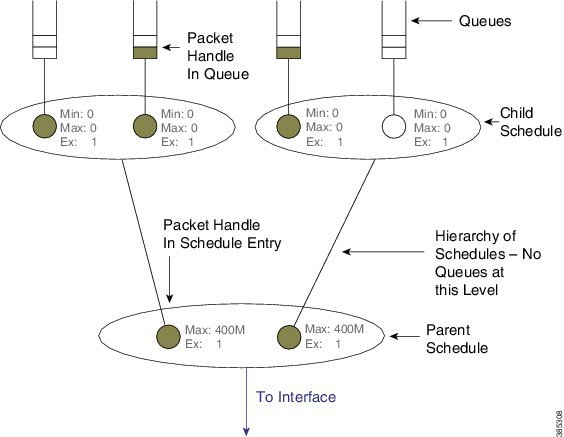
The first thing to notice from the diagram is that we implement a hierarchy of schedules and not a hierarchy of queues. This means that queues exist only at the leaf layers of the hierarchy and that packet handles (the packet representation vehicle) never move from queue to queue. Instead, a single packet handle is loaded into the parent schedule entry (provided a packet is waiting for transmission).
When detailing a scheduling hierarchy we describe schedules as parent or child (or indeed grandchild). These descriptions are relative. A parent schedule is one closer to the root of the hierarchy (closer to the interface). The child of a schedule could be either a schedule or a queue. We may also refer to schedules as a leaf or non-leaf schedule. A leaf schedule has solely queues as children; a non-leaf schedule will have at least one schedule as a child.
Looking at the diagram you can see that the schedule entry in the parent schedule (non-leaf) ) has only two parameters per schedule entry. The Minimum Bandwidth parameter is only supported in leaf schedules – not in non-leaf schedules.
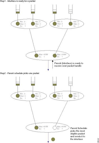
Scheduling Decisions - Root to Leaf
The following sequence of diagrams illustrates how the schedules in a hierarchy work in concert yet make local decisions when selecting the next packet to send through an interface.
Among the packets stored locally, the parent schedule will first decide on the most eligible packet to forward to the interface. After sending the associated packet handle, it will have a free spot in its own schedule entry – no packet handle from the child of that entry exists.
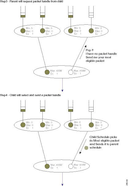
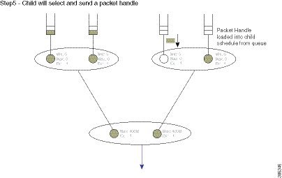
If the child is another schedule, the parent will send it a pop (a message that communicates "you pick your most eligible packet and send me that packet handle"). The child schedule will review the configuration of each entry, decide which packet should be sent next, and forward that packet handle to the parent schedule. The child will now have a free spot in its schedule entry. As the child is a queue no decision is necessary - the packet handle at the head of the queue will be loaded into the (child) schedule entry:
Concept of Priority Propagation
You will notice that thus far the descriptions have been somewhat simplistic in that they have only included bandwidth queues. In truth, for each child, a parent schedule can hold a priority (queue) packet handle and a bandwidth (queue) packet handle (we term this capability passing lanes). When a packet handle is sent from a child schedule to the parent we indicate whether it arose from a priority or a bandwidth class and we also indicate the priority level (we term this behavior priority propagation).
We will examine priority propagation later in this chapter. Here we merely introduce the concept so that the rules of hierarchical scheduling make sense:
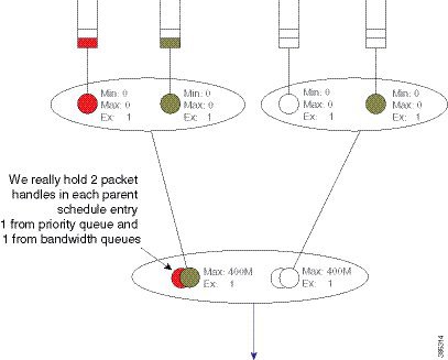
Observe in this hierarchy that priority service does not require configuration in the parent schedule entry; the (parent) schedule entry has only two parameters, Max and Excess Weight.
Hierarchical Scheduling Operation
In the scheduling chapter we describe how scheduling decisions are made for a flat policy attached to a physical interface. Here, we describe the scheduling rules for a leaf schedule (a scenario addressing a schedule with only queues as children). Those rules still hold.
We will now expand on that description to include the rules for the parent-child interaction:
-
Priority traffic counts towards Max (shape command) configured at the parent schedule.
-
Priority traffic is unaltered by Ex (bandwidth remaining ratio command) configured at parent.
-
Priority packets at the parent schedule will always be scheduled before bandwidth packets.
-
Priority will be scheduled proportionally to the shape rate configured at parent. We include this point for completeness; it should not be a factor unless your priority load can oversubscribe the interface.
-
Under priority propagation, a parent will know that a packet came from a priority queue but it will not know whether it was P1 (priority level 1) or P2 (priority level 2).
-
Traffic from queues configured with the bandwidth or the bandwidth remaining commands are treated equally at the parent (no min bandwidth propagation). Henceforward, we refer to traffic from any bandwidth queue as bandwidth traffic.
-
Excess weight configuration at the parent controls the fairness between bandwidth traffic from multiple children competing for any physical bandwidth not consumed by priority traffic.
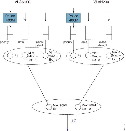
To understand these rules, let's look at the following configuration example. Later, we will detail how a configuration is mapped into a datapath configuration. For now, the diagram and schedule entries shown in the diagram are sufficient to understand the behavior:
policy-map child100
  class priority
    priority
    police cir 400m
  class data
    bandwidth remaining ratio 4
!
policy-map parent100
  class class-default
    shape average 900m
    service-policy child100
!
policy-map child200
  class priority
    priority
    police cir 400m
  class data
    bandwidth remaining ratio 2
!
policy-map parent200
  class class-default
    shape average 900m
    bandwidth remaining ratio 2
    service-policy child200
!
int g1/0/4.100
  encaps dot1q 100
  service-policy out parent100
!
int g1/0/4.200
  encaps dot1q 200
  service-policy out parent200
The following diagram shows the scheduling hierarchy associated with the previous configuration. As described previously, the shape command in the parent policy(s) sets the Max parameter and the bandwidth remaining ratio command sets the Ex parameter in the schedule entry (rules 1 and 2). The latter defaults to 1 if not explicitly set:
Let's now look at the expected throughput for an offered load.
 Note | The following examples ignore overhead accounting – they are intended solely to illustrate how to calculate expected throughput independent of minor details. |
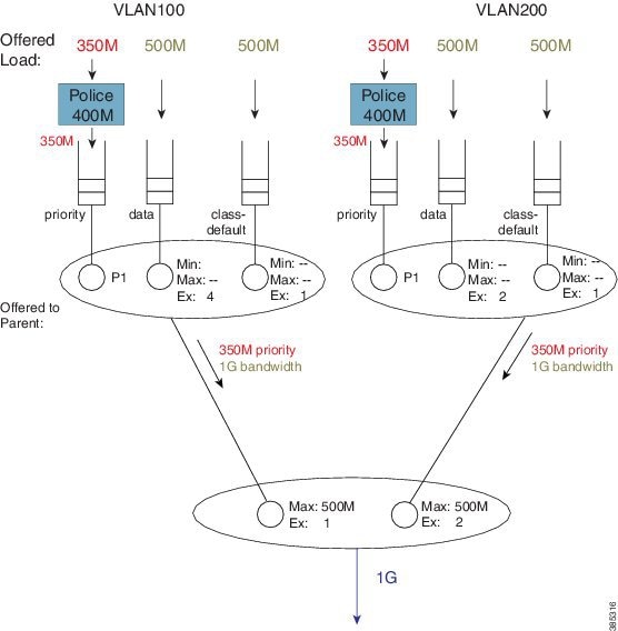
In calculating expected throughput, the first step is to eyeball the offered load per class. The next step is to aggregate them and observe the total loads from priority and bandwidth classes that will be offered to the parent:
Each child schedule is offering 350 Mbps of priority traffic to the parent. Because the interface has 1 Gbps of available bandwidth it will forward the entire 700 Mbps offered priority load.
According to rule 3, we schedule priority traffic before bandwidth traffic. As the Max (rate) for each parent schedule entry exceeds the offered priority load from that entry's child schedule, we forward the entire 350 Mbps of traffic.
With the scheduled priority load (350 Mbps + 350 Mbps of traffic), we can now calculate the (remaining) bandwidth for bandwidth (queue) traffic (300 Mbps or 1 Gbps of total bandwidth available - 700 Mbps consumed by priority load).
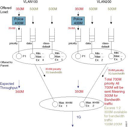
The parent schedule will use the Ex configuration to apportion the 300 Mbps (remaining) bandwidth. With Ex values of 1 and 2, for VLAN100 and VLAN200, respectfully, the bandwidth will be shared 1:2. VLAN100 will receive 100 Mbps and VLAN200 will receive 200 Mbps of bandwidth traffic throughput:
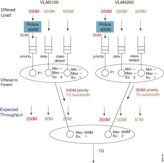
To calculate how this 100 Mbps will be apportioned, we can now examine the bandwidth queue's schedule entries (in the schedule) for VLAN100.
No Min guarantees are configured (the bandwidth command is not supported in parent schedules), so all sharing hinges on the scheduled Ex values in the child schedule. Based on the settings (4 for class data and 1 for class class-default) the 100 Mbps will be shared 4:1 (class data receives 80 Mbps; class class-default receives 20 Mbps).
If we follow the same approach for VLAN200, the 200 Mbps available is split 2:1. Class data will receive 133 Mbps and class class-default will receive 67 Mbps.
You probably noticed that every class was oversubscribed. This means the expected throughput we calculated was also the minimum guaranteed service rate for each class. Under hierarchical scheduling, bandwidth sharing at the parent schedule ensures that we don’t waste bandwidth if any child schedule does not have packets waiting for transmission. Similar to bandwidth sharing in flat policies, bandwidth unused by one child is available to others.
Priority Propagation
Regarding the Concept of Priority Propagation, we will now use the following sample configuration to highlight a few points:
policy-map child
  class voice
    priority
    police cir 600m
  class video
    priority
    police cir 600m
!
policy-map parent100
  class class-default
    shape average 900m
    service-policy child
!
policy-map parent200
  class class-default
    shape average 900m
    bandwidth remaining ratio 2
    service-policy child
!
int g1/0/4.100
  encaps dot1q 100
  service-policy out parent100
!
int g1/0/4.200
  encaps dot1q 200
  service-policy out parent200
Note | We are using the same child policy in both parent policy-maps. Unique policy-maps are unnecessary at any level; if the requirements match, you can share child or even parent policy-maps. |
A hierarchy created for this configuration would look as follows:
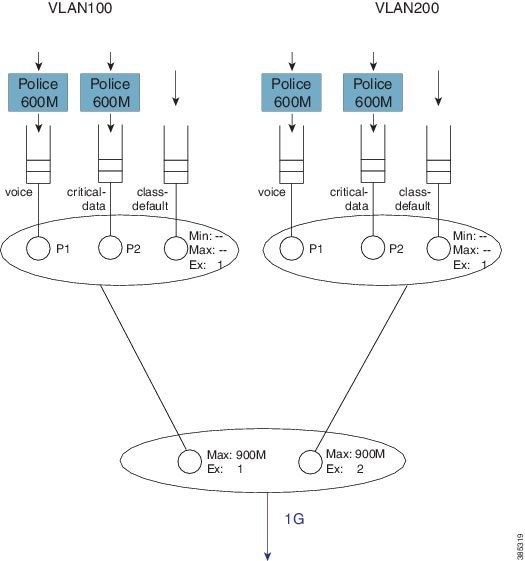
The scenario differs from that in the Concept of Priority Propagation. We now have multi-level priority queuing in the child schedule (e.g., P1 [priority level 1] and P2 [priority level 2] classes). The following diagram shows the load offered to each class:
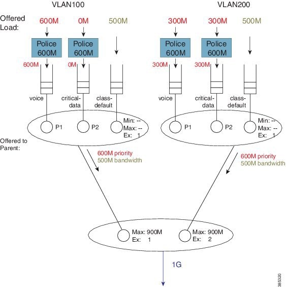
In rule 4 (see Hierarchical Scheduling Operation) we stipulated that a parent will schedule an offered priority load proportional to the shape rate configured in its schedule entry. Here, each child has a Max rate ("shape" in the parent policy) of 900 Mbps and offers 600M priority traffic (i.e. 1.2 Gbps [600M + 300M + 300M traffic] when only 1 Gbps is available). The parent schedule will apportion 500 Mbps to each child. The key point to note here is that P1 from VLAN100 competes equally with P2 traffic from VLAN200. (Recall from rule 5 that priority propagation alerts the parent that a packet arose from a priority queue but does not indicate the priority level.)
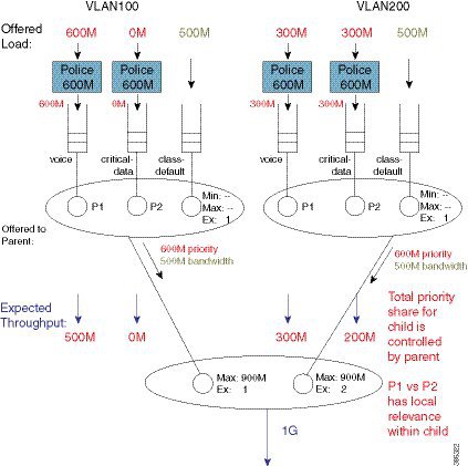
The parent schedule accepts 500 Mbps of priority load from VLAN200. The child schedule is responsible for apportioning bandwidth within that 500 Mbps. The child policy has P1 configured in the voice class, which means that the child schedule will always pick packets from that queue first (i.e., priority levels have local significance within a schedule). The expected throughput for the voice class in VLAN200 is 300 Mbps. The class critical-data will receive 200 Mbps (the unused share of the 500 Mbps – 300 Mbps in this example):
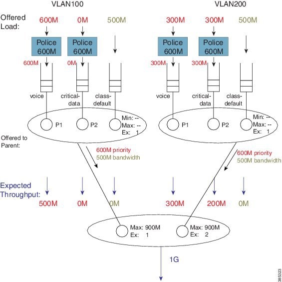
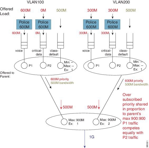
What about the expected throughput from the bandwidth queues? As the offered priority load exceeded the physical bandwidth available, nothing remained for the bandwidth queues. This example effectively highlights that priority classes can starve bandwidth queues completely. If control packets are not in priority queues, you might experience network instability. In fact, failure to place control packets in priority queues could be considered a misconfiguration!
Note | Ensure that the physical bandwidth available exceeds the sum of all priority class policers, so that the latter can’t starve others of service. |
Please be aware that the concept of priority propagation does not end in the scheduling hierarchy. When we mark a packet as stemming from a priority class, that tag is carried to the egress interface. In egress carrier or interface cards, we find multiple places where passing lanes enable priority packets to arrive at the interface as quickly as possible.
Bandwidth Command in Leaf Schedules
We have already stated that although the bandwidth command is not supported in parent schedules (and so a Min setting is absent), it is supported in leaf schedules. With the following configuration, we will explain the operation of the bandwidth command in a child policy-map. (Lines flagged with asterisks indicate how this configuration compares with that presented in Priority Propagation.)
policy-map child100
  class voice
    priority
    police cir 100m
  class critical-data
    bandwidth 300000                 ****
!
policy-map child200
  class voice
    priority
    police cir 100m
  class critical-data
    bandwidth 100000                ****
!
policy-map parent100
  class class-default
    shape average 500m
    service-policy child100
!
policy-map parent200
  class class-default
    shape average 500m
    bandwidth remaining ratio 2
    service-policy child200
!
int g1/0/4.100
  encaps dot1q 100
  service-policy out parent100
!
int g1/0/4.200
  encaps dot1q 200
  service-policy out parent200
A hierarchy created for this configuration would look as follows:
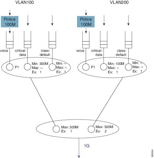
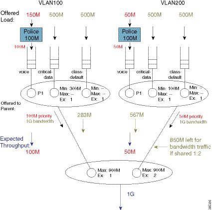
To explain the operation of this hierarchy let's consider the following offered loads (to each class):
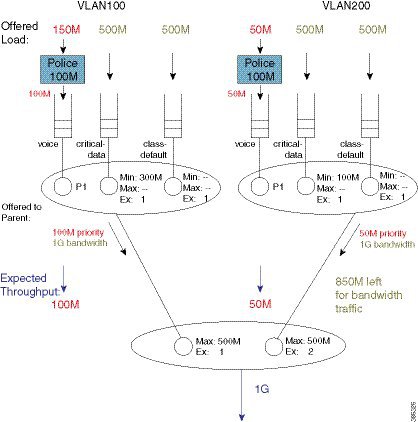
As with the previous example, we first examine the total load offered from the priority and bandwidth queues for each child to the parent.
The total priority load in this example is 150M. Each child is offering less than their Max rate (shape in parent policy) and the aggregate offered-priority load is less than the 1 Gbps total available bandwidth. (Recall the example in Schedule Operation where the total offered priority traffic exceeded the total available bandwidth.) This means the entire priority load offered from each child would be forwarded. With 150 Mbps scheduled from priority queues, we have 850 Mbps available for bandwidth queues.
To calculate how to apportion the bandwidth between each child, let's first look at the excess weight configured in each schedule entry in the parent:
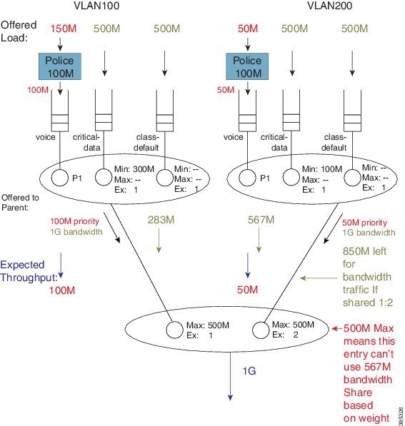
If we focus exclusively on the excess weight, VLAN200 would be apportioned 567 Mbps of the interface bandwidth (2/3 of 850 Mbps). However, we also need to factor in the Max value (500 Mbps) configured in the schedule entry, which includes the 50 Mbps of priority traffic from that child. This means that VLAN 200 will actually forward 450 Mbps of bandwidth traffic and VLAN100 will forward 400 Mbps of bandwidth traffic (850 Mbps - 450 Mbps for VLAN 200):
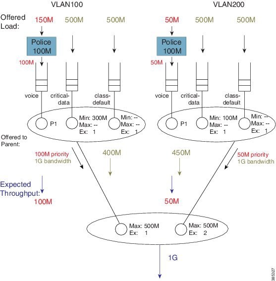
As the sum of the Max values at the parent level is less than or equal to the available physical bandwidth, the Ex values in the parent policies do not add value – each child will receive a total throughput matching its shape rate (e.g., for VLAN100, 100M + 400M = 500M [the shape rate]). Observe that with such a configuration, any bandwidth unused by one child would not be available to another. Any child is always limited to the configured Max value.
With the total throughput for bandwidth classes in each child, we can now calculate the throughput each individual class in that child will receive. Recall from Schedule Operation that Min bandwidth guarantees are always serviced first and any excess bandwidth is shared based on the Ex values, which always default to 1:
For example, the bandwidth apportioned to the class critical-data of VLAN200 would be 275M (100M (Min guarantee) + ½ (450M -100M), where we derive "½" from the Ex ratio of 1:1).
Bandwidth Command is Only Locally Significant
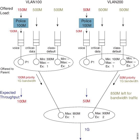
To highlight the risk of using the bandwidth command in hierarchical policies, we will modify the previous configuration example by increasing the parent shapers so that they are no longer the constraining factor. In the revised configuration, the sum of the parent shapers oversubscribes the physical bandwidth available. (Commands flagged with asterisks indicate how this configuration differs from that presented in Bandwidth Command in Leaf Schedules.)
policy-map child100
  class voice
    priority
    police cir 100m
  class critical-data
    bandwidth 300000
!
policy-map child200
  class voice
    priority
    police cir 100m
  class critical-data
    bandwidth 100000
!
policy-map parent100
  class class-default
    shape average 900m                       ****
    service-policy child100
!
policy-map parent200
  class class-default
    shape average 900m                       ****
    bandwidth remaining ratio 2
    service-policy child200
!
int g1/0/4.100
  encaps dot1q 100
  service-policy out parent100
!
int g1/0/4.200
  encaps dot1q 200
  service-policy out parent200
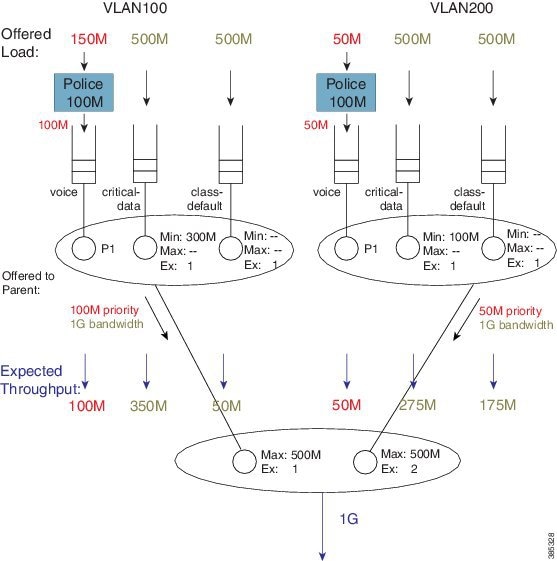
If we apply the offered load profile from Bandwidth Command in Leaf Schedules, the hierarchy and load profile will appear as follows:
Similar to the previous example, 850 Mbps are available (remaining) for bandwidth queues. (Inspecting the sum of priority load and bandwidth traffic share for each child, you notice that the Max value in each parent schedule would not be exceeded.) Based on the excess weights configured in the parent schedule, we calculate the bandwidth share each child would receive (from the parent schedule): 283 Mbps and 567 Mbps.
Note | In contrast to the previous example, because the shape values are no longer constraining, total throughput for each child does not match the shape rate. |
Let's examine the entries in each child schedule to see how bandwidth would be apportioned to each class:
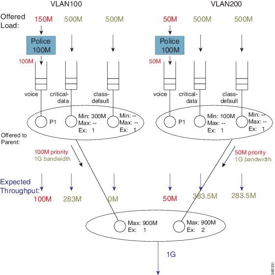
Viewing the child schedule for VLAN100, you notice that the schedule entry for class critical-data has a Min value of 300 Mbps configured. The 283 Mbps bandwidth apportioned to this schedule is insufficient to satisfy this guarantee.
The key point of this discussion is that Min bandwidth guarantees are only locally relevant; Min bandwidth propagation does not exist. Traffic from one child schedule competes equally with excess traffic from another.
Also, please note that using Min in scheduling hierarchies could starve other classes of service (in this example, class-default in VLAN100). To avoid this, use only the bandwidth remaining command in child policies.
Tip
If you oversubscribe parent shapers in a hierarchical policy and want to avoid starving some classes of service, ensure that the sum of policers on your priority queues does not exceed the bandwidth available. Furthermore, consider using the bandwidth remaining over the bandwidth command.
Policy-Maps Attached to Logical Interfaces
Earlier in this chapter, we delineated the two primary methods for creating scheduling hierarchies: QoS policies attached to logical interfaces and hierarchical policy-maps. In prior examples, we outlined polices attached to logical interfaces. Let's explore this scenario in more detail.
- Interface Scheduling
- Shape on Parent, or Queue on Child
- Advantages of Policies on Logical Interfaces
- Multiple Policies Definition and Restrictions
Interface Scheduling
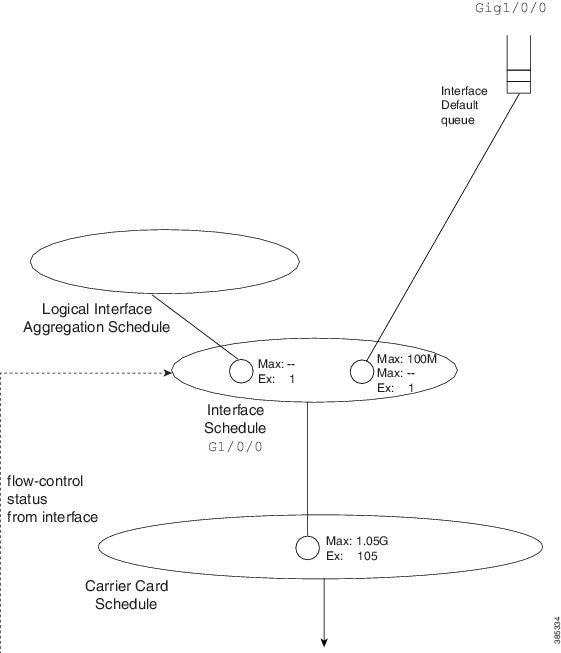
Before looking at how a policy on a logical interface alters the hierarchy, we need to carefully examine the interface schedule and hierarchy that exist before any QoS policy is applied:
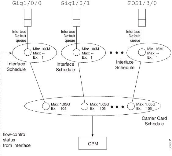
The OPM (Output Packet Module) sits at the root of the scheduling hierarchy. Upon receiving a packet handle, it fetches the actual packet from memory and pushes it towards the physical interface.
Directly below the OPM layer (from a decision-making perspective) you will find the carrier card schedule. On modular platforms we find one such schedule per slot whereas on fixed systems we have one for the entire system.
Consider a modular chassis with one slot housing an SIP10 that has a 10 Gbps link over the backplane to the ESP (Embedded Services Processor – also termed the forwarding processor). The SIP10 can hold 4 SPAs (Shared Port Adapters) where each could have interface(s) totaling at most 10 Gbps capacity. If you combine SPAs in the SIP that exceed the backplane capacity, that link might be a congestion point. Should this occur, the carrier card schedule ensures fairness between interfaces; the excess weight for each interface is proportional to the interface speed.
To condition traffic within a platform, we set the Max value in the carrier card schedule for each interface to slightly exceed the interface’s bandwidth. We want to send enough traffic towards a physical interface such that we never underrun (starve) that interface. Furthermore, we need to quit sending whenever the interface indicates that its egress buffers are filling, which could happen when an interface receives a pause frame from a downstream device, a serial interface expands its data by bit or byte stuffing, etc.
Here is the key: We push traffic towards a physical interface such that it always has data to send down the wire and we temporarily pause sending whenever the interface indicates that it has sufficient data buffered.
An interface directs us to stop sending traffic through a flow-control message. By design, a schedule (not a schedule entry) responds to this message - it stops sending. For this reason we must always have an interface schedule for every physical interface in the box. The interface default queue (the queue used in absence of QoS) is a child of this interface schedule.
Each interface can send distinct high and low priority flow control messages (to the interface schedule), maintaining distinct buffers and queues for priority and bandwidth traffic:
- If the schedule receives a message that bandwidth traffic buffers are filling it will pause such traffic but continue to forward priority traffic.
- If we receive a message that priority buffers are filling we will pause sending any packets until the congestion clears.
This scheme extends the concept of priority propagation to the physical interface (recall that this connotes whether a packet handle stems from a priority or bandwidth class) and minimizes jitter to industry leading levels for latency sensitive traffic.
Shape on Parent, or Queue on Child
Now let’s look at a typical policy that might be attached to a logical interface (a construct referred to as shape on parent or queue on child):
policy-map child100
  class voice
    priority
    police cir 100m
  class critical-data
    bandwidth 300000
!
policy-map parent100
  class class-default
    shape average 900m
    service-policy child100
!
int g1/0/0.100
  encaps dot1q 100
  service-policy out parent100
In this construct, you are required to configure a shaper in the parent policy(shape average 900M). The original intent of this construct was to apportion bandwidth to each logical interface. We consider the shape (Max) rate to be the bandwidth owned by that logical interface and allow the child policy to apportion bandwidth within that owned share.
One useful application of this construct is to condition traffic for a remote site. For example, let's say that your corporate hub has a GigabitEthernet link but is sending traffic to a remote branch with a T1 connection. You want to send traffic at the rate the remote branch can receive it. To avoid potentially dropping packets in the provider device that offers service to that branch, you would configure the parent shaper at a T1 rate and queue packets on the hub. This maintains control of what is forwarded initially if that branch link were a congestion point.
Customers have asked to over-provision the shapers on logical interfaces (representing either individual subscribers or remote sites). The assumption is that all logical interfaces would not necessarily be active at all times. As we want to cap the throughput of an individual subscriber, we don’t want to waste bandwidth if an individual logical interface is not consuming its full allocated share.
So, do we oversubscribe? If yes, to provide fairness under congestion thru excess weight values, you should configure a bandwidth remaining ratio in the parent. Furthermore, be aware of what service any individual logical interface would receive under congestion.
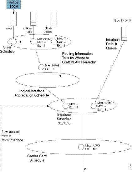
Returning to the configuration, here is the resultant hierarchy:
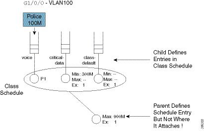
As stated, a child policy defines bandwidth sharing within the logical interface. We usually refer to the queues here (voice, etc.) as class queues (with treatment defined by classes within the policy-map) and the schedule at this layer as the class layer schedule.
In the parent policy we define a parent shaper (Max: 900M) and also the implicit bandwidth share of ‘1’ (Ex: 1). Observe that the QoS configuration does not explicitly specify where we should graft this logical interface to the existing interface hierarchy (note the un-attached schedule entry) and the router must know which physical interface a logical interface is associated with to determine where to build the hierarchy.
For a policy on a VLAN, it is evident which interface is involved - we attach the (logical interface) policy in the subinterface configuration. For other interface types (e.g., a tunnel interface), we may need to examine routing information to determine the egress physical interface for that particular logical interface.
After we know which interface is involved, we can modify the hierarchy for that interface. First we create a schedule (the logical interface aggregation) that will serve as a grafting spot for the logical interface hierarchy defined in the shape on parent (or queue on child) policy.
Initially, the interface schedule had a single child, the interface default queue. Now, we create a second child, the logical interface aggregation schedule. Observe how the excess weight for this schedule matches that of the interface default queue – it defaults to ‘1’ as always.
Notice that in the shape on parent policy, we have only class-default with a child policy:
policy-map parent100
  class class-default
    shape average 900m
    service-policy child100
This is a special case where we just define a schedule entry rather than create a schedule for this policy. We refer to this entity as a collapsed class-default.
To grasp the significance of this concept, let's add a policy to another VLAN (VLAN200). (Relative to the policy-map parent100 listed at the beginning of the topic, we have added asterisks):
policy-map child200
  class voice
    priority
    police cir 100m
  class critical-data
    bandwidth 100000
!
policy-map parent200
  class class-default
    shape average 900m                    ****
    bandwidth remaining ratio 2
    service-policy child200
!
int g1/0/0.200
  encaps dot1q 200
  service-policy out parent200
The complete scheduling hierarchy would now look as follows:
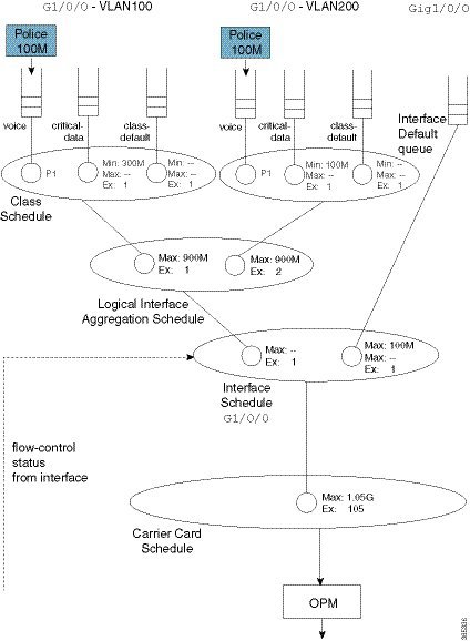
Observe that in the second parent policy (the policy to VLAN200) we specified a bandwidth remaining ratio of 2, controlling fairness between VLANS. Recall from the Qos Scheduling chapter the existence of peers in the parent policy of flat policies, which enable us to use either the bandwidth remaining ratio or bandwidth remaining percent command to specify the excess weight. In the shape on parent policy construct no peers exist. When you configure a QoS policy-map, QoS cannot know what will materialize as peers in the logical interface aggregation schedule. So, neither the bandwidth remaining ratio nor the bandwidth remaining percent command is supported.
This complete scheduling hierarchy truly highlights the benefits of the Cisco Modular QoS CLI (MQC) and the Hierarchical Scheduling Framework (HQF). For any given interface, the hierarchy is deterministic; we know clearly which packet will be forwarded next. As we have schedules to handle all congestion points, no bandwidth is wasted regardless of where congestion may occur.
Advantages of Policies on Logical Interfaces
The ability to attach policy-maps to logical interfaces offers this significant advantage: management in scaled environments and ease of configuration. For each logical interface, you can reuse or create policy-maps. That is, you might attach a policy-map to each of 1000 VLANs configured on an Ethernet-type interface. To review the QoS statistics for an individual logical interface, you can issue the show policy-map interface interface-name.
Be aware that the advantages can also be perceived as dangers. If the physical bandwidth available exceeds the sum of your parent shapers, then examining a single logical interface in isolation suffices. However, if the sum of parent shapers exceeds the physical bandwidth available, you need to consider contention between logical interfaces and how much bandwidth an individual interface is truly guaranteed. Viewing an individual interface in isolation may be misleading.
Multiple Policies Definition and Restrictions
We use Multiple Policies (MPOL) to describe situations where a policy-map is attached to a logical interface while the policy-map is simultaneously attached to the physical interface to which that logical interface is bound (e.g., a VLAN subinterface and the physical Ethernet interface).
MPOL can also refer to instances where policy-maps are attached to different logical interface types that are bound to the same physical interface. For example, imagine a policy attached to both a VLAN subinterface and a tunnel interface, where both exit the same physical interface.
Currently, the ASR 1000 Series Aggregation Service Router supports a very limited implementation of MPOL. If you have a policy-map attached to a logical interface the only policy you can attach to the physical interface is flat with only class-default and a shaper configured, as in the example below. This topology supports scenarios where the service rate (from a provider) differs from the physical access rate. For example, consider a GigabitEthernet interface connection to your provider where you only pay for 200 Mbps of service. As the service provider will police traffic above that rate, you will want to shape everything (you send) to 200 Mbps and apportion that bandwidth locally.
Note | You must attach the policy to the physical interface before you attach it to any logical interface. Furthermore, you can’t attach policy-maps to more than one logical interface type bound to a single physical interface. |
Returning to the previous example of policies attached to two VLAN subinterfaces (see Shape on Parent, or Queue on Child), let's now add a 200 Mbps shaper to the physical interface. The complete configuration would look as follows. The asterisks indicate how this and the previous configuration differ.
policy-map physical-shaper                         ****
  class class-default                              ****
    shape average 200m                             ****
 !
policy-map child100
  class voice
    priority
    police cir 100m
  class critical-data
    bandwidth 300000
!
policy-map child200
  class voice
    priority
    police cir 100m
  class critical-data
    bandwidth 100000
!
policy-map parent100
  class class-default
    shape average 900m
    service-policy child100
!
policy-map parent200
  class class-default
    shape average 900m
    bandwidth remaining ratio 2
    service-policy child200
!
! Note – must attach physical policy before logical policies
!
int g1/0/0                                          ****
  service-policy output physical-shaper             ****
!
int g1/0/0.100
  encaps dot1q 100
  service-policy out parent100
!
int g1/0/0.200
  encaps dot1q 200
  service-policy out parent200
Notice that we have introduced another schedule as well as a queue that will be used for any user traffic sent through the physical interface. The logical interface aggregation schedule has now been created as a child of the physical policy schedule rather than directly as a child of the interface schedule. The combination of traffic through the logical interfaces and user traffic through the physical interface is now shaped to 200 Mbps.
The complete scheduling hierarchy would appear as follows:
Hierarchical Policy-Maps
In the previous sections, we showed how hierarchies are constructed when policy-maps are attached to logical interfaces. A second approach is to use hierarchical policy-maps and explicitly construct the hierarchy you desire. Using this approach you gain some flexibility but loose some scale. (Recall that with policies on logical interfaces you gained management in scaled environments.) The ASR 1000 Series Aggregation Service Router supports up to 1,000 classes in a policy-map, which means that the largest number of logical interfaces you could represent is 1,000.
To belong to a class within a hierarchical policy-map, a packet must match the child and (any) parent classification rules. In an earlier VLAN example we showed how to use VLAN ID-based classification in a parent class and DSCP-based classification in a child class.
The following configuration shows how we might achieve similar behavior to that with a MPOL-physical shaper (see Multiple Policies Definition and Restrictions ). Here we use a three-level hierarchical policy-map (the maximum number of layers we support).
The parent policy has only class-default, which means that all traffic through the interface belongs to this class:
policy-map physicalshaper
  class class-default
    shape average 200m
    service-policy vlansharing
The child level has VLAN-based classification. Traffic belonging to VLAN 100 or VLAN200 will fall into one of the user-defined classes. (Additionally, we have an implicit class-default in this policy that will capture traffic from other VLANs or with no VLAN tag.) Each VLAN class has a policy to further classify traffic based on DSCP:
class-map vlan100
  match vlan 100
class-map vlan200
  match vlan 200
class-map voice
  match dscp ef
class-map critical-data
  match dscp af21
       	!
policy-map child100
 class voice
   priority
   police cir 100m
 class critical-data
   bandwidth 300000
!
policy-map child200
 class voice
   priority
   police cir 100m
 class critical-data
   bandwidth 100000
!
policy-map vlansharing
 class vlan100
   shape average 900m
   bandwidth remaining ratio 1
   service-policy child100
 class vlan200
   shape average 900m
   bandwidth remaining ratio 2
   service-policy child200
!
policy-map physicalshaper
   class class-default
     shape average 200m
    service-policy vlansharing
 !
int g1/0/0
  service-policy output physicalshaper
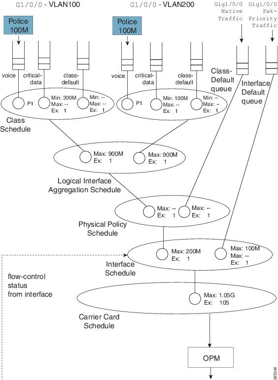
A hierarchy constructed based on the above configuration will look as follows:
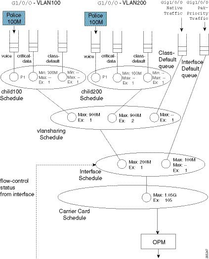
If you compare this hierarchy to the previous MPOL example (Figure 25), you will notice some slight differences.
Firstly, native interface traffic (traffic in neither VLAN 100 nor 200) now shares a vlansharing schedule with the schedule entries for each VLAN. In the MPOL example, the native traffic received an equal share to that of all (both) VLANs (1/2 the available bandwidth). In this hierarchy, in contrast, it is guaranteed only 1/(1 + 2 + 1) of available bandwidth as it competes with the VLANs in the same schedule.
Secondly, with a single policy-map on the physical interface you no longer have the ability to look at statistics for a single VLAN only. Compare this code from the MPOL example:
int g1/0/0
  service-policy output physical-shaper
!
int g1/0/0.100
  encaps dot1q 100
  service-policy out parent100
!
int g1/0/0.200
  encaps dot1q 200
  service-policy out parent200
with this:
int g1/0/0
  service-policy output physicalshaper
The output of the show policy-map interface GigabitEthernet1/0/0 command would reflect all levels of the hierarchical policy-map.
Hierarchical policy-maps can add flexibility that is unachievable with policy-maps on logical interfaces. The following examples illustrate this.
- Example 1. Add Queues for Different Classes of Traffic
- Example 2. Attaching a Policy to Different Logical Interface Types
- A Note on Overhead Accounting
Example 1. Add Queues for Different Classes of Traffic
In the discussion of the MPOL example (and captured in the code snippet below), we noted that the physical interface policy could contain only class-default and a shaper in that class:
policy-map physical-shaper
  class class-default
    shape average 200m
That is, you cannot provide different treatment to unique classes of traffic that were forwarded over the native interface (traffic with no VLAN tag).
In contrast, with an hierarchical construct, we can add queues for different classes of traffic to forward (over the physical interface). For example, if we wanted to add a priority class for voice traffic over the physical interface, we could modify the vlansharing policy-map as follows (see the asterisks):
class-map vlan100
  match vlan 100
class-map vlan200
  match vlan 200
class-map voice
  match dscp ef
class-map critical-data
  match dscp af21
       	!
policy-map child100
 class voice
   priority
   police cir 100m
 class critical-data
   bandwidth 300000
!
policy-map child200
 class voice
   priority
   police cir 100m
 class critical-data
   bandwidth 100000
!
policy-map vlansharing
  class vlan100
    shape average 900m
    bandwidth remaining ratio 1
    service-policy child100
  class vlan200
    shape average 900m
    bandwidth remaining ratio 2
    service-policy child200
  class voice                              ****
    priority                               ****
    police cir 50m                         ****
!
policy-map physicalshaper
  class class-default
    shape average 200m
    service-policy vlansharing
 !

int g1/0/0
  service-policy output physicalshaper
The hierarchy for this configuration would look as follows:
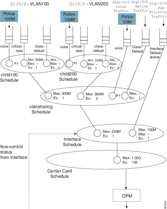
Notice the new capture that captures any traffic marked with the DSCP codepoint of EF but not tagged with VLAN ID of 100 or 200.
Observe in this hierarchy that P1 traffic from a local queue (Gig1/0/0 Voice Traffic) competes with priority propagation traffic in the vlansharing schedule (refer to Concept of Priority Propagation). In such a scenario a local entry configured with priority is serviced before priority propagation traffic. That is, voice packets from a physical interface (Gig1/0/0) have a slightly higher priority than voice packets from VLAN 100 or 200. To avoid starvation of other classes, we use admission control on the priority queues.
Example 2. Attaching a Policy to Different Logical Interface Types
In the section Policy-Maps Attached to Logical Interfaces we indicated that you cannot attach a policy to different logical interface types on the same physical interface. This limitation does not apply to hierarchical class-maps.
Let's say that we want one child schedule for VLAN100 and one child for QoS on a tunnel where both exit the same physical interface. Within the same policy-map, we could classify tunnel traffic using an access list and VLAN traffic using the VLAN ID (see the asterisks):
ip access-list extended tunnel1traffic
  permit ip host 192.168.1.1 host 10.0.0.1
!
class-map vlan100
  match vlan 100
class-map tunnel1traffic
  match access-group name tunnel1traffic
!
class-map voice
  match dscp ef
class-map critical-data
  match dscp af21
       	!
policy-map child
  class voice
    priority
    police cir 100m
  class critical-data
    bandwidth remaining ratio 1
!
policy-map logicalsharing                 ****
  class vlan100
    shape average 900m
    bandwidth remaining ratio 1
    service-policy child
  class tunnel1traffic
    shape average 900m
    bandwidth remaining ratio 2
    service-policy child
!
policy-map physicalshaper
  class class-default
    shape average 200m
    service-policy vlansharing
 !

int g1/0/0
  service-policy output physicalshaper
The hierarchy for this configuration would look as follows:

A Note on Overhead Accounting
In the policing chapter we introduced the concept of policing length (how we perceive a packet's length when a policer evaluates conformance to a configured police rate; see What's Included in the Policer-Rate Calculation (Overhead Accounting)). Similarly, in the scheduling chapter we introduced the concept of scheduling length (how we consider a packet's length when evaluating conformance to a configured scheduler rate; see What's Included in Scheduling Rate Calculations (Overhead Accounting).) By convention, in both cases we include the Layer 2 header and datagram lengths and exclude CRC or interpacket overhead.
With an hierarchical scheduling construct, you might encounter instances where the policing and scheduling lengths differ. To understand this let's examine the execution order of features.
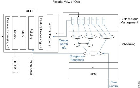
On the ASR 1000 Series Aggregation Services Router, queuing and scheduling is performed in hardware. After we enqueue a packet, hardware assumes control and no further processing is performed – the packet must have all headers and be prepared to traverse the wire. As expected, non-queuing features are performed in microcode on one of the processing elements (with hardware assists, in some instances).
Consider two scenarios.
Configuring a QoS-queuing policy on a GRE tunnel
When we classify an incoming IP packet (ultimately encapsulated in an outer IP/GRE header), we examine just the original IP packet. Consequently, classification statistics will exclude the outer IP/GRE headers as they are missing at the time. As the pictorial view indicates, we perform marking and evaluate policers at this time. Similar to the classification length, the policing length will include neither the outer IP/GRE headers nor any egress Layer 2 header, as we don’t yet know which physical interface or encapsulation type the packet will egress. After QoS non-queuing features we continue processing the packet by adding the outer IP/GRE header and appropriate Layer 2 header for the final egress interface. When all processing concludes, we pass the packet to the WRED/Enqueue block. This action places the packet on the appropriate egress queue in hardware with all headers added; the scheduling length now includes the outer IP/GRE and Layer 2 headers.
Configuring the QoS policy on the physical egress interface
The results differ. When we examine features on the tunnel no QoS is configured and so we proceed to feature processing. Before reaching the QoS policy, we complete all tunnel processing and add egress headers. So, the classification statistics and policing length will now include the outer headers; policing and scheduling lengths will match.
Verification
In all QoS configuration work, the primary tool to verify hierarchical scheduling configurations is the show policy-map interface interface-name command. The output of this command is organized hierarchally, reflecting how we stratify the configuration.
For example, with a hierarchical policy attached to a physical interface you could use the show policy-map interface interface-name| include Class | to display that hierarchy:
show policy-map int g1/0/0 | inc Class

    Class-map: class-default (match-any)
        Class-map: vlan100 (match-all)
            Class-map: voice (match-all)
            Class-map: critical-data (match-all)
            Class-map: class-default (match-any)
        Class-map: vlan200 (match-all)
            Class-map: voice (match-all)
            Class-map: critical-data (match-all)
            Class-map: class-default (match-any)
        Class-map: vlan300 (match-all)
            Class-map: voice (match-all)
            Class-map: class-default (match-any)
        Class-map: voice (match-all)
        Class-map: class-default (match-any)
In this example we have attached a 3-level hierarchical policy to interface GigabitEthernet1/0/0. Indentation in the class-map conveys that hierarchy. Within any class that includes a child policy, the Service-policy: <policy-map name> indicates that the next-indented section pertains to the child policy:
  Class-map: vlan100 (match-all)
          0 packets, 0 bytes
          5 minute offered rate 0000 bps, drop rate 0000 bps
          Match: vlan  100
          Queueing                                                ****
          queue limit 3748 packets                                ****
          (queue depth/total drops/no-buffer drops) 0/0/0         ****
          (pkts output/bytes output) 0/0
          shape (average) cir 900000000, bc 3600000, be 3600000
          target shape rate 900000000
          bandwidth remaining ratio 1

          Service-policy : child100

            queue stats for all priority classes:
              Queueing
              queue limit 512 packets
              (queue depth/total drops/no-buffer drops) 0/0/0
              (pkts output/bytes output) 0/0

            Class-map: voice (match-all)
              0 packets, 0 bytes
              5 minute offered rate 0000 bps, drop rate 0000 bps
              Match:  dscp ef (46)
              Priority: Strict, b/w exceed drops: 0

              police:
                  cir 100000000 bps, bc 3125000 bytes
                conformed 0 packets, 0 bytes; actions:
                  transmit
                exceeded 0 packets, 0 bytes; actions:
                  drop
                conformed 0000 bps, exceeded 0000 bps

            Class-map: critical-data (match-all)
              0 packets, 0 bytes
              5 minute offered rate 0000 bps, drop rate 0000 bps
              Match:  dscp af11 (10)
              Match:  dscp af21 (18)
              Queueing
              queue limit 1249 packets
              (queue depth/total drops/no-buffer drops) 0/0/0
              (pkts output/bytes output) 0/0
              bandwidth 300000 kbps

            Class-map: class-default (match-any)
              0 packets, 0 bytes
              5 minute offered rate 0000 bps, drop rate 0000 bps
              Match: any

              queue limit 3748 packets
              (queue depth/total drops/no-buffer drops) 0/0/0
              (pkts output/bytes output) 0/0
Regarding show command output for a policy containing hierarchical scheduling, observe that any queue-related information in the parent class is meaningless (highlighted by asterisks in the example above). The output format for the show policy-map interface command was created at a time when IOS truly implemented a hierarchy of queues in software. The ASR 1000 Series Aggregation Services Router hardware implements a hierarchy of schedules and queues, which only exist at the leaf. Although the IOS control plane still calculates and displays a queue-limit, it never uses it. So tuning this value is fruitless.
 Feedback