Cisco WDM Series Passive Optical System Installation Note
Available Languages
Table Of Contents
Cisco CWDM Passive Optical System Installation Note
8-Channel Multiplexer/Demultiplexer (CWDM-MUX-8A=)
4-Channel OADM (CWDM-OADM4-1= and CWDM-OADM4-2=)
Dual Single-Channel OADMs (CWDM-OADM1-xxxx)
WDM Splitter Cable (WDM-1300-1550-S=)
CWDM GBIC and CWDM SFP Transceivers
Statement 1071—Warning Definition
Installing the CWDM Passive Optical System
Installing the 2-Slot Chassis (CWDM-CHASSIS-2=)
Installing the CWDM OADM Modules
Installing and Removing CWDM GBIC and CWDM SFP Transceivers
Connecting the CWDM Passive Optical System to Your System
Connecting Cables to the Dual Single-Channel OADM Module
Connecting Cables to the CWDM 4-Channel OADM Module
Connecting Cables to the CWDM 8-Channel Multiplexer/Demultiplexer Module
Statement 1030—Equipment Installation
Statement 1040—Product Disposal
Statement 1053—Class 1M Laser Radiation
Statement 1055—Class I and Class 1M Laser
Statement 1056—Unterminated Fiber Cable
Statement 1057—Hazardous Radiation Exposure
Obtaining Documentation and Submitting a Service Request
Cisco CWDM Passive Optical System Installation Note
This document provides installation instructions for the Cisco Coarse Wave Division Multiplexer (CWDM) passive optical system. The CWDM passive optical system product numbers are listed in Table 1.
Contents
This installation note contains the following sections:
•
Installing the CWDM Passive Optical System
•
Connecting the CWDM Passive Optical System to Your System
•
Obtaining Documentation and Submitting a Service Request
Overview
The Cisco CWDM passive optical system provides optical networking support for high-speed data communication for metropolitan area networks (MANs) over a grid of eight CWDM optical wavelengths in both ring configurations or point-to-point configurations.
The Cisco CWDM passive optical system includes these components:
•
2-slot chassis for Cisco Optical Add/Drop Multiplexers (OADMs)
•
CWDM OADMs
–
8-channel multiplexer/demultiplexer
–
Two 4-channel OADMs
–
Eight dual single-channel OADMs
•
1300 nm/1550 nm WDM splitter cable
•
CWDM GBIC and CWDM SFP transceivers
CWDM 2-Slot Chassis
The CWDM 2-slot chassis (CWDM-CHASSIS-2) is a standard 19-inch chassis that is one rack unit (RU) in height. Each CWDM 2-slot chassis can hold two CWDM OADM modules. You can install the CWDM 2-slot chassis in the same equipment rack as your system or in an adjacent rack so that you can connect the OADMs to the CWDM GBIC transceivers or the CWDM SFP transceivers.
CWDM OADMs
The CWDM OADMs are passive devices that can multiplex/demultiplex or add/drop wavelengths from multiple fibers onto one optical fiber. The OADM connectors are interfaced to the color-matching CWDM GBIC or CWDM SFP transceivers on the equipment side. All OADMs are the same size. Two OADM modules can be installed in a CWDM 2-slot chassis (CWDM-CHASSIS-2). There are three different types of CWDM OADM modules
8-Channel Multiplexer/Demultiplexer (CWDM-MUX-8A=)
The 8-Channel Multiplexer/Demultiplexer (CWDM-MUX-8A=) allows you to multiplex/demultiplex eight separate channels into one pair of fiber. Dual fiber is used for both the network connection and the CWDM GBIC or CWDM SFP transceiver connections. The eight available wavelengths are 1470-nm, 1490-nm, 1510-nm, 1530-nm, 1550-nm, 1570-nm, 1590-nm, and 1610-nm. The multiplexer/demultiplexer, shown in Figure 1, is equipped with a monitor port that allows you to attach a power meter or an optical spectrum analyzer to assist you in monitoring and troubleshooting the network.
Figure 1 8-Channel Multiplexer/Demultiplexer (CWDM-MUX8) Front Panel

4-Channel OADM (CWDM-OADM4-1= and CWDM-OADM4-2=)
The 4-Channel OADM (CWDM-OADM4-1= and CWDM-OADM4-2=) allows you to add/drop four channels (with different wavelengths) into one direction of an optical ring. The other wavelengths are passed through the OADM. The 4-channel OADMs are transparent to the 1300-nm wavelength and includes a 1300-nm/1500-nm filter to mix legacy SONET/SDH/ATM ring installations with CWDM installations on the same optical fiber. Dual fiber is used for both the network and the GBIC or SFP connections. The two 4-channel OADMs, shown in Figure 2 and Figure 3, support the following wavelengths:
•
CWDM-OADM4-1—1470-nm, 1490-nm, 1510-nm, and 1530-nm.
•
CWDM-OADM4-2—1550-nm, 1570-nm, 1590-nm, and 1610-nm.
The 4-channel OADM modules are equipped with a monitor port that allows you to attach a power meter or an optical spectrum analyzer to assist you in monitoring and troubleshooting the network.
Figure 2 4-Channel OADM (CWDM-OADM4-1) Front Panel

Figure 3 4-Channel OADM (CWDM-OADM4-2) Front Panel

Dual Single-Channel OADMs (CWDM-OADM1-xxxx)
The Dual Single-Channel OADMs (CWDM-OADM1-xxxx) allows you to add/drop two channels of the same wavelength into the two directions of an optical ring. The other wavelengths are passed through the OADM. The dual single-channel OADMs are transparent to the 1300-nm wavelength and includes a 1300-nm/1500-nm filter to mix legacy SONET/SDH/ATM ring installations with CWDM installations on the same optical fiber. Dual fiber is used for both the network and the CWDM GBIC and CWDM SFP connections. Eight versions of this OADM are available, one for each wavelength of light. (See Table 2.) The dual single-channel OADMs, shown in Figures 4 through 11, are color coded and match the color coding of the CWDM GBIC and CWDM SFP transceivers. The dual single-channel OADM modules are equipped with a monitor port that allows you to attach a power meter or an optical spectrum analyzer to assist you in monitoring and troubleshooting the network.
Table 3 provides a comparison of the CWDM passive device types.
The OADM module ports are color coded to help with installation. Each color indicates the wavelength of the port. For more information about the color codes, see the "Connecting the CWDM Passive Optical System to Your System" section.
Figure 4 Dual Single-Channel OADM Front Panel (1610 nm)

Figure 5 Dual Single-Channel OADM Front Panel (1590 nm)

Figure 6 Dual Single-Channel OADM Front Panel (1570 nm)

Figure 7 Dual Single-Channel OADM Front Panel (1550 nm)

Figure 8 Dual Single-Channel OADM Front Panel (1530 nm)

Figure 9 Dual Single-Channel OADM Front Panel (1510 nm)

Figure 10 Dual Single-Channel OADM Front Panel (1490 nm)

Figure 11 Dual Single-Channel OADM Front Panel (1470 nm)

WDM Splitter Cable (WDM-1300-1550-S=)
The WDM splitter cable provides bidirectional, multiplexing/demultiplexing for 1310-nm and 1550-nm signals. The WDM splitter cable is a Y cable (see Figure 12) with a 1310-nm branch terminating in an SC connector and a 1550-nm branch terminating in an LC connector. The common trunk branch of the Y cable is terminated in an SC connector. The WDM splitter cable is 1 meter in length.
Figure 12 WDM Splitter Cable

CWDM GBIC and CWDM SFP Transceivers
The CWDM GBIC and CWDM SFP transceivers are hot-swappable input/output devices that link your switching module to the CWDM passive optical system using a pair of single-mode fiber-optic cables. The two transceiver types have different form factors and use different fiber-optic cable connectors. Figure 13 shows a CWDM GBIC transceiver which uses an SC connector, and Figure 14 shows a CWDM SFP transceiver which uses an LC connector.
Figure 13 CWDM GBIC
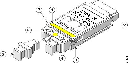
Color label identifying laser wavelength
Optical bore dust plug
Alignment groove
Receive optical bore
Spring clip
Color dot identifying laser wavelength
Transmit optical bore

Warning
Use of controls, adjustments, or performing procedures other than those specified may result in hazardous radiation exposure. Statement 1057
Figure 14 CWDM SFP
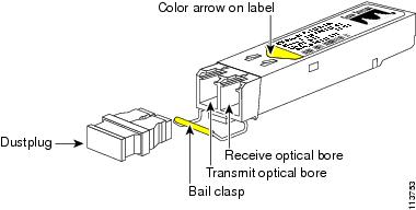
The CWDM GBIC and CWDM SFP transceivers are available in eight wavelengths. (See Table 4.) Each CWDM GBIC and CWDM SFP transceiver is color coded to match the connector colors on the OADM modules.
For information on installing, removing, and maintaining the CWDM GBIC and SFP transceivers, refer to the Cisco CWDM GBIC and CWDM SFP Installation Note that accompanies the CWDM GBIC and CWDM SFP transceivers.
Safety Overview
Throughout this publication, safety warnings appear in procedures that, if performed incorrectly, can harm you. A warning symbol precedes each warning statement.
Statement 1071—Warning Definition

Warning
Only trained and qualified personnel should be allowed to install, replace, or service this equipment. Statement 1030

Warning
Ultimate disposal of this product should be handled according to all national laws and regulations. Statement 1040

Warning
Class I (CDRH) and Class 1M (IEC) laser products. Statement 1055

Warning
Use of controls, adjustments, or performing procedures other than those specified may result in hazardous radiation exposure. Statement 1057

Note
The maximum output is less than 10 mW when measured through a 3.5-mm apeture located at a distance of 100 mm and the wavelength is 1470-nm to 1610-nm from the multichannel MUX or OADM module output connectors. Other fiber-optic ports have been tested and comply with the Class 1 limits of IEC 60825-1 and Class 1 limits of 21 CFR 1040.10 (with considerations pursuant to FDA Laser Notice 50, dated July 26, 2001).
Installing the CWDM Passive Optical System
The following sections provide installation procedures for the CWDM passive optical system components:
•
Installing the 2-Slot Chassis (CWDM-CHASSIS-2=)
•
Installing the CWDM OADM Modules
•
Removing the CWDM OADM Module
•
Installing and Removing CWDM GBIC and CWDM SFP Transceivers
Required Tools
You will need these tools to install the CWDM passive optical system:
•
Number 2 Phillips screwdriver for the 10-32 or the 12-24 chassis installation screws.
•
Wrist strap or other personal grounding device to prevent ESD occurences.
•
Antistatic mat or antistatic foam to set the equipment on.
•
Fiber-optic end-face cleaning tools and inspection equipment. For complete information on inspecting and cleaning fiber-optic connections, refer to the white-paper document at this URL:
http://www.cisco.com/en/US/tech/tk482/tk607/technologies_white_paper09186a0080254eba.shtml
•
Level (optional)
•
Tape measure (optional)
Installing the 2-Slot Chassis (CWDM-CHASSIS-2=)

Note
Ensure that you install the 2-slot chassis in the same rack or an adjacent rack to your system so that you can connect all the cables between your CWDM OADM modules and the CWDM GBIC and CWDM SFP transceivers in your system.

CautionWhen performing the following procedures, wear a grounding strap to avoid ESD damage to the OADM module. Some platforms have an ESD connector for attaching the wrist strap.
To mount the 2-slot chassis in an equipment rack, follow these steps:
Step 1
Remove the 2-slot chassis from the shipping packaging.
Step 2
Position the 2-slot chassis in the rack where you are going to install it. Align the mounting holes in the chassis L brackets with the mounting holes in the equipment rack to ensure that the 2-slot chassis is mounted straight and level. Use a level or tape measure to verify that the chassis is positioned level in the rack.
Step 3
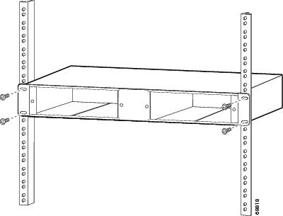
Secure the 2-slot chassis using four (two per side) 12-24 x 3/4-inch screws or four 10-32 x 3/4-inch screws. Thread the screws through the elongated holes in the L bracket and into the threaded holes in the mounting post. (See Figure 15.)
Figure 15 Mounting the 2-Slot Chassis in the Rack
Installing the CWDM OADM Modules

CautionWhen performing the following procedures, wear a grounding strap to avoid ESD damage to the OADM module. Make sure the other end of the ground strap is securely attached to a grounded point.
To install the CWDM OADM modules, follow these steps:
Step 1
Align the CWDM OADM module with the slot on the 2-slot chassis. (See Figure 16.)
Figure 16 Installing a CWDM OADM Module

Step 2
Gently push the OADM module into the 2-slot chassis. Ensure that you line up the captive screws on the OADM module with the screw holes on the 2-slot chassis.
Step 3
Tighten the two captive screws with the Number 2 Phillips screwdriver. Do not overtighten.
Step 4
Do not remove the optical bore dust plugs at this time.
Removing the CWDM OADM Module

CautionWhen performing the following procedures, wear a grounding strap to avoid ESD damage to the OADM module.
To remove the OADM module or the multiplexer/demultiplexer module, follow these steps:
Step 1
Disconnect all network interface cables from the OADM module and immediately install dust plugs in the network interface cable connectors and the OADM connectors.
Step 2
Loosen the captive screw on each side of the OADM module or the multiplexer/demultiplexer module using a Phillips screwdriver.
Step 3
Gently pull on both captive screws to release the OADM module or the multiplexer/demultiplexer module from the 2-slot chassis.
Step 4
Pull the OADM module or the multiplexer/demultiplexer module out of the 2-slot chassis, and place it on an antistatic mat or antistatic foam pad.
Installing and Removing CWDM GBIC and CWDM SFP Transceivers
For information on installing, removing, and maintaining the CWDM GBIC transceivers and CWDM SFP transceivers, refer to the Cisco CWDM GBIC and CWDM SFP Installation Note that accompanies the CWDM GBIC and CWDM SFP transceivers.

CautionCWDM SFP and CWDM GBIC transceivers are static-sensitive devices. Always use an ESD wrist strap or similar individual grounding device when handling or coming in contact with CWDM SFP and CWDM GBIC transceivers.

Note
To prevent contamination, do not remove the optical bore dust plugs from the CWDM SFP and CWDM GBIC transceivers until directed to do so.
Connecting the CWDM Passive Optical System to Your System
This section is divided into the following topics:
•
Connecting Cables to the Dual Single-Channel OADM Module
•
Connecting Cables to the CWDM 4-Channel OADM Module
•
Connecting Cables to the CWDM 8-Channel Multiplexer/Demultiplexer Module

Note
Use the CWDM passive optical system connector color codes shown in Table 2 to help you connect the CWDM passive optical system to your system.
See Figure 2 through Figure 13 for the OADM and multiplexer/demultiplexer module front panels.

Warning
Class 1M laser radiation when open. Do not view directly with optical instruments. Statement 1053
Connecting Cables to the Dual Single-Channel OADM Module

Note
Make sure that the CWDM GBIC or CWDM SFP transceiver color code matches the color of the OADM port to which it is connected.
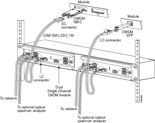
To connect the cables to the dual single-channel OADM module, follow these steps (see Figure 17):
Step 1
Insert the CWDM GBIC or CWDM SFP transceivers into the appropriate modules on your switch or router system if you have not already done so. For more information on CWDM SFP and CWDM GBIC GBIC transceivers, refer to the Cisco CWDM GBIC and CWDM SFP Installation Note that accompanied your transceivers.

Note
Always use single-mode fiber-optic patch cables to connect dual single-channel OADM ports to the CWDM GBIC or the CWDM SFP transceivers.

Note
CWDM GBIC transceivers are equipped with SC connectors. To make connections to the LC connectors on the OADM modules, you must use an LC to SC patch cable (Cisco part number CAB-SM-LCSC-1M= [1 meter cable], CAB-SM-=LCSC-5M= [5 meter cable], or an equivalent patch cable).

Warning
Invisible laser radiation may be emitted from the end of the unterminated fiber cable or connector. Do not view directly with optical instruments. Viewing the laser output with certain optical instruments (for example, eye loupes, magnifiers, and microscopes) within a distance of 100 mm may pose an eye hazard. Statement 1056
Figure 17 Cabling a CWDM Dual Single-Channel OADM Module

Note
Before removing the dust plugs and making any optical connections, observe the following guidelines:
•
Always keep the protective dust plugs on the unplugged fiber-optic cable connectors and the transceiver optical bores until you are ready to make a connection.
•
Always inspect and clean the SC connector end-faces just before making any connections. Refer to the Tip on this page for a pointer to a fiber-optic inspection and cleaning white paper.
•
Always grasp the SC connector housing to plug or unplug a fiber-optic cable.
Step 2
Remove the dust plugs from the network interface cable connector and the transceiver optical bore. Save the dust plugs for future use.
Step 3
Inspect and clean the connector's fiber-optic end-faces. Refer to the Tip below for a pointer to the fiber-optic inspection and cleaning white paper.

Tip
For complete information on inspecting and cleaning fiber-optic connections, refer to the whitepaper at this URL:
http://www.cisco.com/en/US/tech/tk482/tk607/technologies_white_paper09186a0080254eba.shtml
Step 4
Connect the single-mode fiber-optic patch cable from the CWDM GBIC or CWDM SFP transceiver to the OADM module EQUIPMENT connector. Connect the Tx ports to the Rx ports and the Rx ports to the Tx ports to ensure that the system operates correctly.
a.
If you are using CWDM SFP transceivers, use an LC-to-LC patch cable.
b.
If you are using CWDM GBIC transceivers, you must use an SC-to-LC patch cable (CAB-SM-LCSC-1M= or CAB-SM-LCSC-5M=).

Note
CWDM GBIC transceivers are equipped with SC connectors. To make connections to the LC connectors on the OADM modules, you must use an LC to SC patch cable (Cisco part number CAB-SM-LCSC-1M= [1 meter cable], CAB-SM-=LCSC-5M= [5 meter cable], or an equivalent patch cable).
Step 5
If you use both channels of the module, repeat Step 4 for the second channel.
Step 6
Connect the network west backbone single-mode fiber-optic cable to the NETWORK WEST connector on the OADM module, and connect the east backbone single-mode fiber-optic cable to the NETWORK EAST connector on the OADM module.
Step 7
If you are planning to monitor your network with an optical power meter or an optical spectrum analyzer, connect your meter or analyzer to the MONITOR port on the OADM.
Connecting Cables to the CWDM 4-Channel OADM Module

Note
Make sure that the CWDM GBIC or CWDM SFP transceiver color code matches the color of the OADM port to which it is connected.
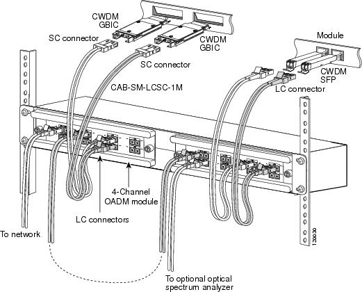
To connect the cables to the CWDM 4-channel OADM module, follow these steps (see Figure 18):
Step 1
Insert the CWDM GBIC transceivers or CWDM SFP transceivers into the appropriate modules on your switch or router system if you have not already done so. For more information on installing CWDM GBIC or CWDM SFP transceivers, refer to the Cisco CWDM GBIC and CWDM SFP Installation Note.

Note
Always use single-mode fiber-optic patch cables to connect the CWDM OADM ports to the CWDM GBIC transceivers or CWDM SFP transceivers.

Note
CWDM GBIC transceivers are equipped with SC connectors. To make connections to the LC connectors on the OADM modules, you must use an LC to SC patch cable (Cisco part number CAB-SM-LCSC-1M= [1 meter cable], CAB-SM-=LCSC-5M= [5 meter cable], or an equivalent patch cable).

Warning
Invisible laser radiation may be emitted from the end of the unterminated fiber cable or connector. Do not view directly with optical instruments. Viewing the laser output with certain optical instruments (for example, eye loupes, magnifiers, and microscopes) within a distance of 100 mm may pose an eye hazard. Statement 1056
Figure 18 Cabling a 4-Channel OADM Module

Note
Before removing the dust plugs and making any optical connections, observe the following guidelines:
•
Always keep the protective dust plugs on the unplugged fiber-optic cable connectors and the transceiver optical bores until you are ready to make a connection.
•
Always inspect and clean the SC connector end-faces just before making any connections. Refer to the Tip on this page for a pointer to a fiber-optic inspection and cleaning white paper.
•
Always grasp the SC connector housing to plug or unplug a fiber-optic cable.
Step 2
Remove the dust plugs from the network interface cable connector and the transceiver optical bore. Save the dust plugs for future use.
Step 3
Inspect and clean the connecor's fiber-optic end-faces. Refer to the Tip below for a pointer to the fiber-optic inspection and cleaning white paper.

Tip
For complete information on inspecting and cleaning fiber-optic connections, refer to the whitepaper at this URL:
http://www.cisco.com/en/US/tech/tk482/tk607/technologies_white_paper09186a0080254eba.shtml
Step 4
Connect the single-mode fiber-optic cables from the CWDM GBICs (Tx/Rx; up to four channels) to the 4-channel module equipment connectors (Tx/Rx; up to four wavelengths, 1470-nm, 1490-nm, 1510-nm, 1530-nm) for OADM4-1 or 1550-nm, 1570-nm, 1590-nm, and 1610-nm for OADM4-2.

Note
Connect the Tx ports to the Rx ports and the Rx ports to the Tx ports to ensure that the system operates correctly.
Step 5
Connect the one backbone single-mode fiber-optic cable to the NETWORK connector on the OADM module, and connect the other backbone single-mode fiber-optic cable to the PASS connector on the OADM module.
Step 6
If you are planning to monitor your network with an optical power meter or an optical spectrum analyzer, connect your meter or analyzer to the MONITOR port on the OADM.
Connecting Cables to the CWDM 8-Channel Multiplexer/Demultiplexer Module

Note
Make sure that the CWDM GBIC transceiver color code or CWDM SFP transceiver color code matches the color code of the OADM port to which it is connected.
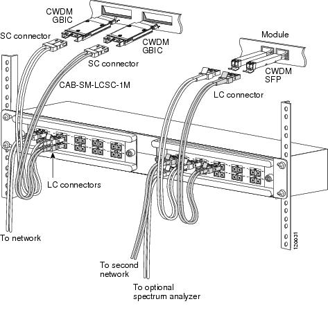
To connect cables to a CWDM 8-channel multiplexer/demultiplexer module, follow these steps (see Figure 19):
Step 1
Insert the CWDM GBIC or CWDM SFP transceivers into the appropriate modules on your switch or router system if you have not already done so. For more information on installing CWDM GBIC transceivers and SFP transceivers, refer to the Cisco CWDM GBIC and CWDM SFP Installation Note.

Note
Clean all fiber-optic plugs on the cables before inserting the plugs into the fiber-optic connectors.

Note
Always use single-mode fiber-optic patch cables to connect the 8-channel multiplexer/demultiplexer ports to the CWDM GBIC transceivers and CWDM SFP transceivers.

Warning
Invisible laser radiation may be emitted from the end of the unterminated fiber cable or connector. Do not view directly with optical instruments. Viewing the laser output with certain optical instruments (for example, eye loupes, magnifiers, and microscopes) within a distance of 100 mm may pose an eye hazard. Statement 1056
Figure 19 Cabling a CWDM 8-Channel Multiplexer/Demultiplexer Module

Note
Before removing the dust plugs and making any optical connections, observe the following guidelines:
•
Always keep the protective dust plugs on the unplugged fiber-optic cable connectors and the transceiver optical bores until you are ready to make a connection.
•
Always inspect and clean the SC connector end-faces just before making any connections. Refer to the Tip on this page for a pointer to a fiber-optic inspection and cleaning white paper.
•
Always grasp the SC connector housing to plug or unplug a fiber-optic cable.
Step 2
Remove the dust plugs from the network interface cable connector and the transceiver optical bore. Save the dust plugs for future use.
Step 3
Inspect and clean the connecor's fiber-optic end-faces. Refer to the Tip below for a pointer to the fiber-optic inspection and cleaning white paper.

Tip
For complete information on inspecting and cleaning fiber-optic connections, refer to the white-paper document at this URL:
http://www.cisco.com/en/US/tech/tk482/tk607/technologies_white_paper09186a0080254eba.shtml
Step 4
Connect the single pair fiber-optic cables from the CWDM GBIC transceivers or CWDM SFP transceivers (Tx/Rx; up to eight channels) to the 8-channel multiplexer/demultiplexer module equipment connectors (Tx/Rx; up to eight wavelengths).

Note
CWDM GBIC transceivers are equipped with SC connectors. To make connections to the LC connectors on the multiplexer/demultiplexer device, you must use an LC to SC patch cable (Cisco part number CAB-SM-LCSC-1M= [1 meter cable], CAB-SM-LCSC-5M= [5 meter cable], or an equivalent patch cable).

Note
Connect the Tx ports to the Rx ports and the Rx ports to the Tx ports to ensure that the system operates correctly.
Step 5
Connect the network backbone single pair fiber-optic cable to the multiplexer/demultiplexer NETWORK connector on the OADM module.
Step 6
If you are planning to monitor your network with an optical power meter or an optical spectrum analyzer, connect your meter or analyzer to the MONITOR port on the OADM.
Specifications
Table 5 lists the environmental specifications for the CWDM OADM and multiplexer/demultiplexer modules. Table 6 lists the optical specifications for the CWDM OADM and multiplexer/demultiplexer modules.
Translated Safety Warnings
This section contains the translations to the warnings that appear in this publication.
Statement 1030—Equipment Installation
Statement 1040—Product Disposal
Statement 1053—Class 1M Laser Radiation
Statement 1055—Class I and Class 1M Laser
Statement 1056—Unterminated Fiber Cable
Statement 1057—Hazardous Radiation Exposure
Obtaining Documentation and Submitting a Service Request
For information on obtaining documentation, submitting a service request, and gathering additional information, see the monthly What's New in Cisco Product Documentation, which also lists all new and revised Cisco technical documentation, at:
http://www.cisco.com/en/US/docs/general/whatsnew/whatsnew.html
Subscribe to the What's New in Cisco Product Documentation as a Really Simple Syndication (RSS) feed and set content to be delivered directly to your desktop using a reader application. The RSS feeds are a free service and Cisco currently supports RSS Version 2.0.

Contact Cisco
- Open a Support Case

- (Requires a Cisco Service Contract)


 Feedback