Catalyst 6500 Series Switch and Cisco 7600 Series Router Network Analysis Module Release 3.4 Configuration Note
Bias-Free Language
The documentation set for this product strives to use bias-free language. For the purposes of this documentation set, bias-free is defined as language that does not imply discrimination based on age, disability, gender, racial identity, ethnic identity, sexual orientation, socioeconomic status, and intersectionality. Exceptions may be present in the documentation due to language that is hardcoded in the user interfaces of the product software, language used based on RFP documentation, or language that is used by a referenced third-party product. Learn more about how Cisco is using Inclusive Language.
- Updated:
- March 22, 2005
Chapter: Troubleshooting the NAM
Troubleshooting the Network Analysis Module
This chapter describes how to troubleshoot the NAM and includes these sections:
•![]() Web Username and Password Guidelines
Web Username and Password Guidelines
•![]() Local Interfaces in the NAM ifTable
Local Interfaces in the NAM ifTable

Note ![]() Additional troubleshooting help is available to the NAM Traffic Analyzer application users in the online help "Troubleshooting" section.
Additional troubleshooting help is available to the NAM Traffic Analyzer application users in the online help "Troubleshooting" section.
Netflow Data Export
This section contains troubleshooting information for NDE.
Web Application
Explanation When you are on the Monitor > Hosts, Monitor > Apps, or Monitor > Conversations page, the data shows only every other or more auto-refresh cycles. This problem is caused by the implementation operation of the NDE source device. Entries in the NetFlow cache are expired after being inactive for a time, when the end of a connection is detected, or when the expiration time has been reached. The expired flow is exported to the destination. If the aging time is longer than the NAM refresh interval, there will be no expired flows and NetFlow packets flow in one refresh interval of the NAM.
Recommended Action To solve the problem, either increase the auto refresh interval on the Setup > Preferences menu, or change the aging time of the NetFlow entries. Before you make any change to the aging time at the NDE source device, refer to the NDE usage guidelines for performance issues.
Cisco IOS Software
For the MSFC or routers, use the following command to specify the aging time:
Router(config)# ip flow-cache timeout "active"||"inactive" seconds
Router(config)# mls aging "fast time" | "long" | "normal" seconds
Catalyst Operating System Software
For the PFC, use the following commands to specify the aging time:
Console(enable) set mls agingtime [long-duration | fast | ip]
To set the aging time for flows that are long active, use the long-duration keyword.
To set the aging time for flows that do not exceed the packet threshold, use the fast keyword.
To set the aging time for IP flows, use the ip keyword.
Explanation The Monitor > Hosts and Monitor > Conversations page does not contain the data of an active flow. This problem could be caused if the active flow is not expired yet, if the device has an NDE filter, or if a full cache is preventing insertion of new entries. The active flow is not in the NetFlow packets that are exporting to the NAM.
Recommended Action Check the filter long duration aging time or dropped flow packets as follows:
Verify the long duration aging time with these commands:
Console(enable) show ip cache flow
or
Console(enable) show mls netflow aging
or
Console(enable) show mls
Active flows that have their active time below the long duration aging time are not expired yet, and they have not been exported to the NAM. You can set the aging time to a lower value. Refer to the NDE usage guidelines for the device.
Verify the dropped flow packets with these commands:
Console(enable) show ip cache flow
or
Console(enable) show mls netflow aging
or
Console(enable) show mls
Flows could drop because they are not entered into the caches allowing their export to the NAM when they are expired. The NetFlow cache might be full because of busy networks. To correct the problem, you could increase the cache size, or adjust NDE export with the NDE flow mask or version 8 aggregation cache. Refer to the NDE usage guidelines for the device.
Explanation There is no data for the default NetFlow data source of the device.
Recommended Action In the GUI, go to the Setup > Data Sources > NetFlow > Listening Mode page and click on Start. Wait for a few auto refresh cycles. If the device is not displayed in the table, the NAM is not receiving any NetFlow packets from the device. This condition could be a network problem, or the device may not be configured correctly.
To verify that a NetFlow device is configured to send NetFlow packets to UDP port 3000 of the NAM, use the following commands:
Console> show ip flow export
or
Console> show mls nde
Displayed information should show whether or not NetFlow export is enabled or disabled and show the IP address and port to which the NetFlow packets are being exported. If the information is not correct, refer to the configuration section in the User Guide for the Network Analysis Module Traffic Analyzer Release 3.3.
Explanation There is no data for NetFlow data sources that are configured for specific interfaces, but the default NetFlow data source for the device has data.
Recommended Action This problem could occur because a NetFlow record that contains contains nformation about the specified interfaces does not exist. To find out which interfaces the NetFlow records have, follow these steps:
Step 1 ![]() Go to the Setup > Data Sources > NetFlow > Listening Mode screen.
Go to the Setup > Data Sources > NetFlow > Listening Mode screen.
Step 2 ![]() Click Start to initiate the listening process.
Click Start to initiate the listening process.
Step 3 ![]() Wait until the row for the device has more than three NDE packets counted.
Wait until the row for the device has more than three NDE packets counted.
Step 4 ![]() Select the device.
Select the device.
Step 5 ![]() Click Details. A window appears displaying a list of interfaces that the NAM has seen in the NDE packets.
Click Details. A window appears displaying a list of interfaces that the NAM has seen in the NDE packets.
Step 6 ![]() Make sure that the interfaces selected for the NetFlow devices are included in the list. If the interfaces are not included in the list, configure the NetFlow source devices using the following commands:
Make sure that the interfaces selected for the NetFlow devices are included in the list. If the interfaces are not included in the list, configure the NetFlow source devices using the following commands:
For the IP routed cache, use these commands:
Console(config) interface type slot/port
Console(config-if) ip route cache flow
For the MLS cache, use these commands for Cisco IOS software:
Console(config)# mls nde interface
For the MLS cache, use these commands for the Catalyst operating system software:
Console>(enable) set mls nde destination-ifindex enable
or
Console(enable) set mls nde source-ifindex enable
Make sure that the flow mask is set to full, interface-destination-source, or interface-full.
If the information is not correct, refer to the configuration section in the User Guide for the Network Analysis Module Traffic Analyzer Release 3.3.
Explanation When creating a NetFlow data source from the Setup > Data Sources > NetFlow > Custom Data Sources screen, only the local device's address appears in the drop-down box.
Recommended Action A device is created in the Setup > Data Sources > NetFlow > Devices screen. After adding a device from this screen, a default NetFlow data source for the device appears in the Setup > Data Sources > Netflow > Custom Data Sources screen. Now, the drop-down box displays the device address included in the list.
Explanation When creating a NetFlow data source, no available interfaces list is displayed.
To make sure that the community string is correct, follow these steps:
Step 1 ![]() Go to the Setup > Data Sources > NetFlow > Devices menu.
Go to the Setup > Data Sources > NetFlow > Devices menu.
Step 2 ![]() Click on the radio button of the device to display information about the interfaces.
Click on the radio button of the device to display information about the interfaces.
Step 3 ![]() Click Test.
Click Test.
A popup window appears displaying the status of the device. If there is an error in this window, the community string may not be correct. Correct the community string by selecting the device, click Edit, and provide the correct community string. Also, ensure that the remote device accepts SNMP connections.
Explanation The Monitor > Conversations page has the source column as 0.0.0.0 for all entries. This problem occurs when the NDE device flow mask is set to destination.
Cisco IOS Software
If using Cisco IOS software to set the flow mask to full, interface-destination-source, or interface-full, enter this command:
Router(config)# mls flow ip "full"||"interface-destination-source"||"interface-full"
Catalyst Operating System Software
If using Catalyst operating system software to set the flow mask to full, interface-destination-source, or interface-full, enter this command:
Console(enable)# set mls flow "destination-source" || "full"
Note ![]() The NAM supports NDE versions 1, 5, 6, 7, 8, source-prefix, destination-prefix, prefix, and protocol-port aggregations.
The NAM supports NDE versions 1, 5, 6, 7, 8, source-prefix, destination-prefix, prefix, and protocol-port aggregations.
NDE Flow Records Interfaces
Explanation An NDE packet has multiple NDE flow records. Each flow record has fields of flow input SNMP if-index and flow output SNMP if-index. The information may not be available due to an unsupported NDE feature of the Cisco IOS or Catalyst operating system version or misconfiguration of the NDE flow masks.
Figure 5-1 and Figure 5-2 show the network configuration for this situation, and Table 5-1 and Table 5-2 show the reporting flow records.
Figure 5-1 NDE Configuration
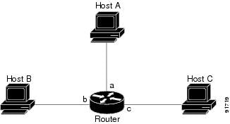
The configuration is as follows:
Router# configuration terminal
Router(config)# interface a
Router(config-if)# ip route cache flow
Router(config-if)# exit
Router(config)# ip flow export destination NAM-Address 3000
Router config)# exit
Router#
|
|
|
|
|---|---|---|
a |
b |
Yes |
a |
c |
Yes |
b |
c |
No |
b |
a |
No |
c |
a |
No |
c |
b |
No |
Figure 5-2 NDE Configuration
Router# configuration terminal
Router(config)# interface a
Router(config-if)# ip route cache flow
Router(config-if)# exit
Router(config)# interface b
Router(config-if)# ip route cache flow
Router(config-if)# exit
Router(config)# ip flow export destination NAM-Address 3000
Router(config)# exit
Router#
|
|
|
|
|---|---|---|
a |
b |
Yes |
a |
c |
Yes |
b |
c |
Yes |
b |
a |
Yes |
c |
a |
No |
c |
b |
No |
Recommended Action In most cases, turning on NetFlow on an interface will populate the NetFlow cache in a switch or router with flows that are in the input direction of the interface. As a result, the input SNMP if-index field in the flow record will have the if-index of the interface that has NetFlow turned on.
Interface Special (0)
Explanation NDE packets sometimes have NetFlow records reporting either or both input if-index and output if-index fields as 0. This problem may be due to one or more of the following reasons:
–![]() Flows that are terminated at the device.
Flows that are terminated at the device.
–![]() Configurations of the device.
Configurations of the device.
–![]() Unsupported NetFlow feature of the platform at the device.
Unsupported NetFlow feature of the platform at the device.
Recommended Action Remove flows that terminate at the device, check the device configuration, and make sure that there are no unsupported features on this platform at the device.
NDE Flow Mask and Version 8 Aggregation Cache
This section describes how some of the flow masks and NDE version 8 aggregation flows affect the data collection screens in the NAM. Table 5-3 lists the effects on the data collection screens. Due to a lack of information, some collections may display "Others" only in the Monitor > Apps, 0.0.0.0 in Monitor > Hosts and Monitor > Conversation pages.
Error Messages
Symptom When a reset command is entered from the supervisor CLI, the system always boots into the maintenance image.
Possible Cause If the boot device is configured in the supervisor engine as cf:1, typing a reset module command always boots to the maintenance image.
Recommended Action Override the configured boot device in the supervisor engine by entering the boot string during reset.
•![]() In Cisco IOS software, to boot to the application image, use the hw-module mod 9 reset hdd:1 command.
In Cisco IOS software, to boot to the application image, use the hw-module mod 9 reset hdd:1 command.
•![]() In Catalyst operating system software, to boot to the application image, use the reset 9 hdd:1 command.
In Catalyst operating system software, to boot to the application image, use the reset 9 hdd:1 command.
Symptom You receive a verification failed message when installing a patch on the NAM.
Possible Cause The cause could be that the time and date on the NAM are not correct, the patch is not the same as an official Cisco patch, the patch might be from a previous release of the NAM, the FTP process may have failed, or the FTP image being pointed to is not a patch (it may be a full application image).
Recommended Action Make sure that the signature verification is used to ensure that the patch is an authentic Cisco patch and that the patch is for the correct NAM release. For example, a patch for the NAM 2.2 release cannot be applied to a NAM running the NAM 3.3 software. Make sure that the date and time on the NAM is set to synchronize with the switch or with the Network Time Protocol (NTP). Make sure that the URL location is valid for the patch (verify the username)
Symptom You are unable to log into the maintenance image with the same password for the NAM application image.
Note ![]() This message is applicable only for the WS-SVC-NAM-1 and the WS-SVC-NAM-2 modules.
This message is applicable only for the WS-SVC-NAM-1 and the WS-SVC-NAM-2 modules.
Possible Cause The NAM application image and the maintenance image have different password databases for the root and guest accounts. The default passwords for root and guest differ between the maintenance image and the NAM application image. Any password change performed in the NAM application image does not change the maintenance image password and vice versa.
Recommended Action Use the maintenance image password.
Symptom You lost your password for the maintenance image and want to recover it.
Possible Cause The maintenance image does not support resetting passwords from the switch. Upgrading the maintenance image sets the password for root and guest to default in the maintenance image.
Recommended Action Use the default maintenance image passwords. Refer to Table 4-1 on page 4-2 or Table 4-4 on page 4-12.
Symptom When attempting to load the new NAM 3.3 image on the NAM, the following message displays:
Incompatible image! Upgrade aborted.
Possible Cause This image is not supported on the specified NAM. Two NAM 3.3 images are available: One each for the WS-SVC-NAM-1 and WS-SVC-NAM-2. This symptom occurs only if an incompatible image is used.
Recommended Action The newer NAM shares a common format and the same image filename for upgrades can be used.
Symptom When attempting to load the wrong image on a WS-SVC-NAM-1 or WS-SVC-NAM-2, the following message displays:
ERROR: /tmp/upgrade:No space left on device
Possible Cause This image is not supported on the specified NAM. Two NAM 3.3 images are available: One each for the WS-SVC-NAM-1 and WS-SVC-NAM-2. This symptom occurs only if an incompatible image is used.
Recommended Action The application and maintenance file image formats are different between the previous NAM releases and the newer WS-SVC-NAM-1 and WS-SVC-NAM-2. The newer NAM shares a common format, and the same image filename for upgrades can be used between these newer modules.
Symptom A SPAN session does not show up in the Traffic Analyzer Active SPAN window.
Possible Cause In Catalyst operating system software, a SPAN session becomes inactive if the module containing the destination port is removed from the switch chassis. The NAM is not seen by the SPAN session because the SPAN configuration is removed from the SNMP agent by the supervisor engine.
Recommended Action Replace the module.
Symptom In Cisco IOS software, a SPAN create request failed for a partially configured SPAN session.
Possible Cause The NAM does not see this partial SPAN session, or the SPAN create request can fail if there is a conflict in either the source type or destination port.
Recommended Action Because the SPAN session can be partially defined with either source or destination only, reconfigure the SPAN session with both a source and destination.
Symptom When the NAM initially boots, by default it runs a partial memory test and you want to run a complete memory test.
Possible Cause The partial memory test is the default configuration.
Recommended Action To perform a full memory test, enter the hw-module module module_number reset device:partition mem-test-full command.
Note ![]() A full memory test takes significantly more time to complete.
A full memory test takes significantly more time to complete.
This command is specific to Cisco IOS software and is not available in Catalyst operating system software. (See the "Resetting the NAM with Catalyst Operating System Software" section on page 4-14.)
You can also use the hw-module module module_number mem-test-full command as follows:
Router(config)# hw-module module 5 mem-test-full
For the Catalyst operating system software, you can enable a full memory test when you use the set boot device bootseq mod# mem-test-full command. This option is disabled by default. This example shows how to enable a full memory test:
Console (enable) set boot device cf:1 4 mem-test-full
Device BOOT variable = cf:1
Memory-test set to FULL
Warning:Device list is not verified but still set in the boot string.
Console> (enable) show boot device 4
Device BOOT variable = cf:1
Memory-test set to FULL
This example shows how to reset the partial memory test:
Console> (enable) set boot device cf:1 4
Device BOOT variable = cf:1
Memory-test set to PARTIAL
Warning:Device list is not verified but still set in the boot string.
Console> (enable)
Console> (enable) show boot device 4
Device BOOT variable = cf:1
Memory-test set to PARTIAL
Symptom When you click the Test button in the Set up > Switch Parameters menu window, the popup window indicates that both the SNMP read and write to the switch failed.
Possible Cause Verify that the SNMP read-write community string is the same as the SNMP read-write community string defined for the switch.
Note ![]() The password is case sensitive.
The password is case sensitive.
Recommended Action If the community string is correct and the test still fails, check that the switch has enabled the IP permit list as follows:
Step 1 ![]() Log in to the switch in enable mode.
Log in to the switch in enable mode.
Step 2 ![]() Enter the show IP permit command.
Enter the show IP permit command.
If the IP permit list is enabled, make sure that the NAM internal address is added to the IP permit list. The NAM address is 127.0.0.X, where X is the NAM module number multiplied by 10 plus 1. For example, if the NAM is at module 4, then its address should be 127.0.0.41.
After you determine the NAM internal IP address, go to Step 3.
Step 3 ![]() Enter the set IP permit NAM-address SNMP command.
Enter the set IP permit NAM-address SNMP command.
Symptom When a NAM is running in a switch with Catalyst operating system software, the NAM may be shown as unreachable when you use the ping command or the NAM Traffic Analyzer application.
Possible Cause The NAM IP address and the IP address of the switch (interface sc0) are not in the same subnet. This problem can occur if you change the switch IP address and the NAM VLAN assignment. The NAM automatically synchronizes its VLAN assignment to the same VLAN in which the switch (interface sc0) resides. When this occurs, the NAM IP address resides on a different subnet from the VLAN assigned to the NAM. The router then drops any packet destined to the NAM IP address. You cannot add a static route to the router because of route overlap caused by improper VLAN assignments and subnetting.
Recommended Action Make sure that the NAM IP address and the switch are in the same subnet and in the same VLAN.
Symptom You cannot connect to the NAM.
Possible Cause The initial configuration is incorrect or not configured.
Recommended Action Reconfigure the NAM as described in the "Configuring the NAM" section on page 3-1.
Symptom You cannot connect to the NAM Traffic Analyzer application.
Possible Cause The configuration for the HTTP server is not correct.
Recommended Action Check the NAM configuration for the HTTP server as described in the "Configuring the HTTP or HTTP Secure Server" section on page 3-13.
Symptom The NAM fails to upgrade.
Possible Cause The URL to the server or the image name is incorrect.
Recommended Action Make sure that the URL you specified is valid. Make sure that the image name you specified in the URL is an official Cisco image name.
Symptom You cannot enable the HTTP server.
Possible Cause No web users are configured, or a secure server is already enabled.
Recommended Action Configure web users as described in the "Configuring the HTTP or HTTP Secure Server" section on page 3-13.
Symptom After configuration, the TACACS+ authentication and authorization fails.
Possible Cause There are three possible causes: The name and password do not match the login configuration in the TACACS+ server, the TACACS+ secret key configured in the NAM does not match the secret key configured in the server, or the wrong TACACS+ server IP address is configured in the NAM.
Recommended Action To determine the cause of the problem, follow these steps:
Step 1 ![]() Log in as a local user.
Log in as a local user.
Step 2 ![]() Choose Admin > Diagnostics > Tech Support.
Choose Admin > Diagnostics > Tech Support.
Step 3 ![]() Scroll down to view the /var/log/messages area.
Scroll down to view the /var/log/messages area.
Step 4 ![]() Look for the following messages near the end of the log and take the recommended actions:
Look for the following messages near the end of the log and take the recommended actions:
...PAM-tacplus[612]:auth failed:Login incorrect
Possible Cause The name and password do not match the login configuration in the TACACS+ server.
Recommended Action Log in to the TACACS+ server and configure the authentication and authorization for the NAM user. (See the TACACS+ documentation for information on login configuration.)
...httpd:tac_authen_pap_read:invalid reply content, incorrect key?
...PAM-tacplus[616]:auth failed:Authentication error, please contact administrator.
Possible Cause The TACACS+ secret key configured in the NAM does not match the key in the TACACS+ server.
Recommended Action Choose Admin > User > TACACS+ and enter the correct secret key.
...httpd:tac_connect:connection to 172.18.122.183 failed:Connection timed out
...httpd:tac_connect:all possible TACACS+ servers failed
...PAM-tacplus[613]:connection failed srv 0:Connection timed out
...PAM-tacplus[613]:no more servers to connect
Possible Cause The wrong TACACS+ server IP address is configured on the NAM.
Recommended Action Choose Admin > User > TACACS+ and enter the correct TACACS+ server address.
Symptom The TACACS+ user can log in successfully but receives the "Not authorized..." error messages when accessing the NAM Traffic Analyzer application.
Possible Cause You do not have the necessary access rights.
Recommended Action Log in to the TACACS+ server and grant access rights to the affected users. (See the TACACS+ documentation for information on login configuration.)
Symptom When importing a configuration using the configure network command, the configuration file download succeeds, but the import operation fails and displays an error.
Possible Cause The configuration file is not correct.
Recommended Action Use the show log config command to determine where the configuration failed. You could either ignore or correct the configuration file and enter the config network command again.
Symptom When upgrading an application image from a NAM-1 or a NAM-2 to a maintenance image, this message displays:
Image verification failed.
Possible Cause The image that you are trying to upgrade is not a valid maintenance image or is not compatible with this release.
Recommended Action You need to use the correct maintenance image for the NAM-1 or the NAM-2. Do not use the WS-X6380-NAM maintenance image.
Symptom When upgrading from a WS-X6380-NAM application image, this message displays:
Incompatible image! Upgrade aborted.
Possible Cause The WS-X6380-NAM image cannot be used on the NAM-1 or NAM-2.
Recommended Action You need to use the correct maintenance image for the WS-X6380-NAM. Do not use the NAM-1 or NAM-2 maintenance image.
Symptom When upgrading the WS-X6380-NAM maintenance image, this message displays:
restore operation failed.
Possible Cause There was a problem with the upgrade process.
Recommended Action Load the WS-X6380-NAM application image to correct this problem.
Web Username and Password Guidelines
Observe the following web username and password guidelines:
•![]() You cannot use the CLI username (root or guest) and password to log into the NAM Traffic Analyzer application because they are administered separately. You also cannot use your NAM Traffic Analyzer username and password to log into the NAM CLI.
You cannot use the CLI username (root or guest) and password to log into the NAM Traffic Analyzer application because they are administered separately. You also cannot use your NAM Traffic Analyzer username and password to log into the NAM CLI.
You can create web users with a local database or using TACACS+. You can create a web user with the same username and password as used on the CLI. However, you must still make password changes in both places.
•![]() You can use TACACS+ in addition to a local database or instead of a local database. (The local database is always checked first.) To use only TACACS+, eliminate the local database users by either of these methods:
You can use TACACS+ in addition to a local database or instead of a local database. (The local database is always checked first.) To use only TACACS+, eliminate the local database users by either of these methods:
–![]() Use the NAM CLI rmwebusers command to remove only local users, not TACACS+ users, because they are administered separately on the TACACS+ server.
Use the NAM CLI rmwebusers command to remove only local users, not TACACS+ users, because they are administered separately on the TACACS+ server.
–![]() From the Admin tab, click Users, and then delete all local database users individually.
From the Admin tab, click Users, and then delete all local database users individually.

•![]() You can recover the password in situations where you have forgotten the local web admin user password, or when another user with account permission logged in and changed the local web admin user password.
You can recover the password in situations where you have forgotten the local web admin user password, or when another user with account permission logged in and changed the local web admin user password.
To recover the passwords, follow these steps:
Step 1 ![]() Access the NAM CLI.
Access the NAM CLI.
Step 2 ![]() Enter these commands:
Enter these commands:
web-user
user name name
exit
Step 3 ![]() At the prompt, enter the new password.
At the prompt, enter the new password.
Step 4 ![]() Enter Y to confirm the new password.
Enter Y to confirm the new password.
When the NAM TACACS+ setting is misconfigured and a local database user account is not available to fix this problem from the web interface, you may be able to fix the TACACS+ configuration by using the CLI interface.
To recover the passwords, follow these steps:
Step 1 ![]() Access the NAM CLI.
Access the NAM CLI.
Step 2 ![]() Enter this command:
Enter this command:
ip http tacacs+ enable tacacs+ server
Step 3 ![]() Follow the commands to enter the TACACS+ secret key.
Follow the commands to enter the TACACS+ secret key.
Supported MIB Objects
Table 5-4 lists the RMON and RMON2 MIB objects supported by the supervisor engine and the NAM. The supervisor engine implements some objects from the RMON MIBs as specified in Table 5-4. The supervisor engine RMON implementation is completely independent of the NAM implementation, and no MIB objects are shared.
To collect etherStats from a physical interface on the switch, configure the etherStatTable on the supervisor engine instead of on the NAM. The etherStats are collected accurately on multiple physical interfaces simultaneously.
If you are interested in the etherStats for a specific VLAN, configure the etherStatsTable on the NAM. For the data source, use the ifIndex corresponding to that VLAN.
Any alarmVariable configured on the supervisor engine must reference a MIB object on the supervisor engine. An alarmVariable configured on the NAM must reference a MIB object on the NAM.
Note ![]() You cannot configure an alarmVariable on the NAM that references a MIB object on the supervisor engine or configure an alarmVariable on the supervisor engine that references a MIB object on the NAM.
You cannot configure an alarmVariable on the NAM that references a MIB object on the supervisor engine or configure an alarmVariable on the supervisor engine that references a MIB object on the NAM.
Local Interfaces in the NAM ifTable
This section explains the differences between the newer NAM-1 and NAM-2 and the previous version of the WS-X6380-NAM. The three versions of the Network Analysis Module (NAM) are as follows:
•![]() WS-X6380-NAM
WS-X6380-NAM
•![]() WS-SVC-NAM-1
WS-SVC-NAM-1
•![]() WS-SVC-NAM-2
WS-SVC-NAM-2
The WS-X6380-NAM appears in the supervisor engine CLI and ifTable as two ports. The first port, the data port, is used for receiving SPAN traffic. The second port is the management port. On the NAM, these two ports show up in the ifTable as the first two ports (with ifIndex.1 for data and ifIndex.2 for management).
The WS-SVC-NAM-1 appears in the supervisor engine CLI (in the Catalyst operating system) and ifTable as three ports. The first port is unused. The second port is the management port. The third port is the data port (for receiving SPAN traffic). The supervisor engine CLI (in Cisco IOS software) parses the ports to ("analysis module . . ."). On the NAM's ifTable, the management port appears as the first port (ifIndex.1) and the data port appears as the second (ifIndex.2).
The WS-SVC-NAM-2 appears in the supervisor engine CLI (in the Catalyst operating system) and ifTable as eight ports. Ports 1, 3, 4, 5, and 6 are unused. Port 2 is the management port (the same as on WS-SVC-NAM-1). Ports 7 and 8 are both data ports and can be SPAN targets. The supervisor engine CLI (in the Cisco IOS software) parses the ports to ("analysis module . . ."). On the NAM's ifTable, the interfaces are as follows:
•![]() ifIndex.1: Is designated the management port.
ifIndex.1: Is designated the management port.
•![]() ifIndex.2: Represents the traffic from both data ports (also known as "All SPAN").
ifIndex.2: Represents the traffic from both data ports (also known as "All SPAN").
•![]() ifIndex.3: Represents the traffic from the first data port (named "data port 1")
ifIndex.3: Represents the traffic from the first data port (named "data port 1")
•![]() fIndex.4: Represents the traffic from the second data port (named "data port 2")
fIndex.4: Represents the traffic from the second data port (named "data port 2")
Note ![]() For the WS-SVC-NAM-1 and WS-SVC-NAM-2, the data ports are IEEE 802.1Q trunk ports. Packets are received with an 802.1Q header (except for packets with the ports native VLAN ID), affecting offsets (for example, the filters on the IP headers) in the packets.
For the WS-SVC-NAM-1 and WS-SVC-NAM-2, the data ports are IEEE 802.1Q trunk ports. Packets are received with an 802.1Q header (except for packets with the ports native VLAN ID), affecting offsets (for example, the filters on the IP headers) in the packets.
Table 5-5 lists the local interface designations for the NAM.
 Feedback