Installing Cisco uBR-MC3GX60V Cable Interface Line Cards - Quick Start Guide
Available Languages
Contents
- Installing Cisco uBR-MC3GX60V Cable Interface Line Cards
- Overview
- Cable Bundles for the Line Card
- SFP Transceiver Modules for the Line Card
- Safety Information and Warnings
- Electrical Equipment Guidelines
- Preventing Electrostatic Discharge Damage
- Installing the Line Card in the Card Slot
- Cabling the Line Card
- Installing Cables
- Installing the UCH2
- Installing the SFP Module on the Line Card
- SFP Module Interface Cables
- RJ-45 Connector
- SC Fiber-Optic Connector
- LC Fiber-Optic Connector
- Connecting a Network Cable to an SFP Module
- Removing the Line Card
- Removing the UCH2
- Removing Cables
- Removing the Line Card
- Removing the SFP Module From the Line Card
- Troubleshooting the Line Card Installation
- Technical Specifications and Component Part Numbers
- Part Numbers
- Physical Specifications and Compliance Information
- Related Documentation
- Obtaining Documentation and Submitting a Service Request
Installing Cisco uBR-MC3GX60V Cable Interface Line Cards
First Published: November 2010, OL-24911-01
Revised: November 2010, OL-24911-01
Overview
The Cisco cable interface line card transmits and receives RF signals between the subscriber and the headend over the hybrid fiber-coaxial (HFC) system. This DOCSIS 3.0 compliant line card is designed specifically for the Cisco uBR10012 universal broadband router and conforms to the Modular CMTS (M- CMTS) architecture.
The Cisco cable interface line card has the capacity to support 72 downstream (DS) and 60 upstream (US) channels, depending on the license purchased. The line card supports 15 cable MAC domains (cable interfaces), and the DS and US channels can be associated with any of these 15 MAC domains. Each MAC domain supports a maximum of 32 DS and 8 US channels.
The Cisco cable interface line card has 20 US spigots for RF connectivity, which are organized into 5 groups of 4 connectors each. Each connector group supports up to 12 frequency-stacked US channels, with a default configuration of 3 US channels per RF connector. The line card also provides the flexibility to configure lesser number of US spigots. For example, you can configure 10 US spigots with a frequency-stacking of 6 US channels per spigot.
The Cisco cable interface line card has six Gigabit Ethernet (GE) interface ports organized into three pairs for DS connectivity. Each pair supports 1+1 redundancy and supports 24 DS channels in Annex B mode by default. The GE interfaces connect to an external Edge Quadrature Amplitude Modulation (EQAM) device and provide M-CMTS compliant Downstream External PHY Interface (DEPI) data. This data is directed to only one GE interface, though both the GE interfaces can be active at the same time.
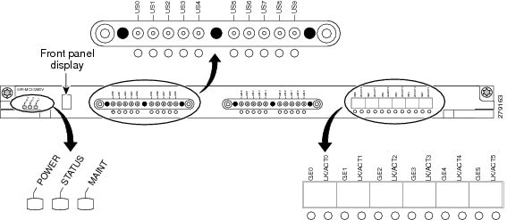
The Cisco cable interface line card uses a front panel display (FPD) to show the licensing status information of the US and DS channels.
Figure 1 shows the face plate of the line card. The product ID (PID) of this card is UBR-MC3GX60V.
Table 1 shows some of the US and DS channel combinations supported on the Cisco line card and their corresponding license type.
For more information on the Software Licensing feature, refer to the Cisco uBR-MC3GX60V Cable Interface Line Card Hardware Installation Guide.
Note
You must ensure that two DOCSIS Timing, Communication and Control (DTCC) cards are configured in the DOCSIS Timing Interface (DTI) mode on the Cisco uBR10012 router to make the Cisco cable interface line card work with an EQAM device.Cable Bundles for the Line Card
The Cisco cable interface line card uses bundled cables. The cables come in bundles of five cables. Quad-shield coaxial cable bundles for the Cisco cable interface line card can be purchased from Cisco, with the Universal Cable Holders (UCH) already connected to the coaxial cable bundles. Alternatively, custom-length quad-shield coaxial cable bundles can be purchased from third-party vendors, with the UCH either connected to the cable bundles or provided as separate components.
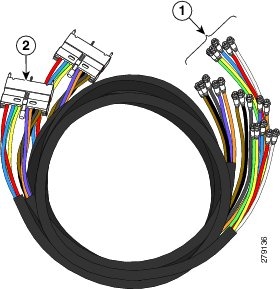
Figure 1 shows the cable bundle for Cisco cable interface line card to EQAM or hybrid fiber-coaxial (HFC) plant that has 20 F connectors attached to one end and 2 UCH2 units attached to the other end. This cable is 9.84 feet (3 m) long and its part number is CABRFSW3G60QTIMF2.
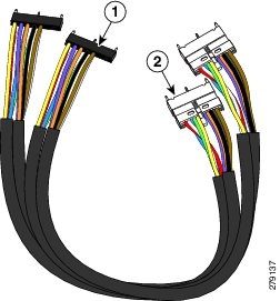
Figure 2 shows the cable bundle for the Cisco cable interface line card to the RF Switch, which has two UCH2 units attached to one end and two RF Switch header blocks attached to the other end. This cable is 3.2 feet (1 m) long and its part number is CABRFSW3G60QTIMM2.
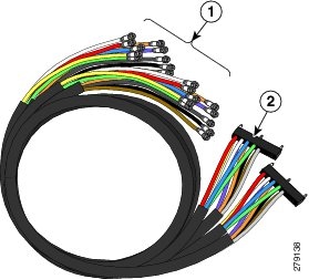
Figure 3 shows the cable bundle for the RF Switch to HFC plant, which has 2 RF Switch header blocks attached to one end and 20 F connectors attached to the other end. This cable is 9.84 feet (3 m) long and its part number is CABRFSW3G60QTPMF2.
Note
Customers purchasing custom-length quad-shield coaxial cable bundles from third-party vendors can purchase spare Universal Cable Holders and spare RF Switch header blocks from Cisco. For the applicable Cisco part numbers, see Part Numbers.
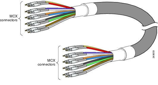
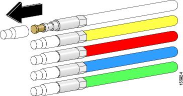
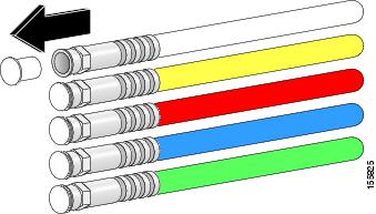
Figure 4 shows a Cisco dual-shielded cable bundle. This dual-shielded cable configuration can be used when you are cabling the Cisco line card directly to the cable plant.
If you are cabling the line card to the Cisco uBR 3X10 RF Switch, you must have MCX connectors at either end of the cable. See Figure 4.
Caution
The Cisco cable interface line card must be used with the provided UCH2 for all cable connections to the line card. Failure to use the UCH2 may cause permanent damage to the line card connectors, resulting in low or no RF output in the downstream or upstream.
Note
The cable used with the dense connector UCH2 must be 75–ohm precision miniature video cable. For the applicable Cisco part numbers, see Table 1.
SFP Transceiver Modules for the Line Card
The Cisco cable interface line card has three pairs of GE ports that use small form-factor pluggable (SFP) modules for fiber-optic and copper links. The SFP modules are I/O devices that plug into a GE port, linking the port to an EQAM device or network through a network cable.
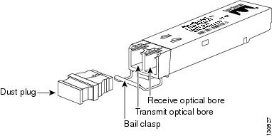
Figure 1 shows the SFP transceiver module that is used with fiber-optic LC connectors.
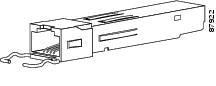
Figure 2 shows the 1000Base-T SFP transceiver module that is used with RJ-45 connectors.
You can use any SFP module that the Cisco line card supports. Table 1 lists the SFP modules that are supported on the Cisco line card. The only restrictions are that each SFP module must match the wavelength specifications on the other end of the cable and that the cable must meet the stipulated cable length range for reliable communications.
Table 2 SFP Modules for the Cisco Line Card SFP Module Product Number SFP Module Description SFP-GE-T RJ-45 copper SFP module (1000BASE-T) Provides full-duplex Gigabit Ethernet connectivity to high-end workstations, and between wiring closets over an existing copper network infrastructure. GLC-SX-MM Short wavelength (1000BASE-SX) Contains a Class 1 laser of 850 nm for 1000BASE-SX (short-wavelength) applications. GLC-LH-SM Long wavelength/long haul (1000BASE-LX/LH) Contains a Class 1 laser of 1310 nm for 1000BASE-LX/LH (long-wavelength) applications. GLC-ZX-SM Extended distance (1000BASE-ZX) Contains a Class 1 laser of 1550 nm for 1000BASE-ZX (extended-wavelength) applications.
Note
Use only Cisco SFP transceiver modules on your Cisco device. Each SFP transceiver module has an internal serial EEPROM that is encoded with security information. This encoding allows Cisco to identify and validate that the SFP transceiver module meets the requirements for the device.The SFP transceiver modules provide duplex single-mode and multimode connections in supported devices. Table 2 lists the cable specifications for SFP module ports.
Table 3 SFP Transceiver Module Cabling Specifications SFP Module Model Speed
Wavelength (nanometers)
Fiber Type Core Size (micron)
Modal Bandwidth (MHz/km)
Cable Distance SFP-GE-T (1000BASE-T)
— Copper — — 328 feet (100 m) GLC-SX-MM (1000BASE-SX)
850 MMF1 62.5
62.5
50.0
50.0
160
200
400
500
722 feet (220 m)
902 feet (275 m)
1640 feet (500 m)
1804 feet (550 m)
GLC-LH-SM (1000BASE-LX/LH)
1300 MMF2 SMF3
62.5
50.0
50.0
G.652
500
400
500
—
1804 feet (550 m)
1804 feet (550 m)
1804 feet (550 m)
32,810 feet (10 km)
GLC-ZX-SM (1000BASE-ZX)4
1550 SMF G.652 — 43.4 to 62 miles (70
to 100 km)
1 Multimode fiber (MMF)2 A mode-conditioning patch cord is required at all times as per IEEE specifications.3 Single-mode fiber (SMF)4 For the GLC-ZX-SM, the minimum attenuation between the transmit bore (TX) and the receive bore (RX) is 8 dB. When using shorter distances of single-mode fiber cable, you might need to insert an inline optical attenuator in the link to avoid overloading the receiver.Safety Information and Warnings
Follow these safety guidelines when working with any equipment that connects to electrical power.
Electrical Equipment Guidelines
Follow these basic guidelines when working with any electrical equipment:
- Before beginning any procedures requiring access to the chassis interior, locate the emergency power-off switch for the room in which you are working.
- Disconnect all power and external cables before moving a chassis.
- Do not work alone when potentially hazardous conditions exist.
- Never assume that power has been disconnected from a circuit; always check.
- Do not perform any action that creates a potential hazard to people or makes the equipment unsafe.
- Carefully examine your work area for possible hazards such as moist floors, ungrounded power extension cables, and missing safety grounds.
Preventing Electrostatic Discharge Damage
Electrostatic discharge (ESD) damage, which occurs when electronic cards or components are improperly handled, can result in complete or intermittent failures. The AC input power shelf and its AC power modules contain a printed circuit card that is fixed in a metal carrier. Electromagnetic interference (EMI) shielding and connectors are integral components of the carrier. Although the metal carrier helps to protect the cards from ESD, use an anti-static wrist strap each time you handle the modules.
Follow these guidelines for preventing ESD damage:
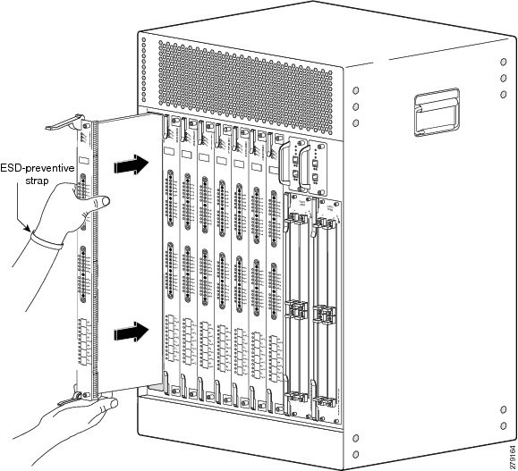
- Always use an ESD-preventive wrist or ankle strap and ensure that it makes good skin contact. Before removing a card from the chassis, connect the equipment end of the strap to a bare metal, unpainted surface on the chassis or rack-mount. Ensure that the chassis and/or rack has a grounding cable installed. For more information, see the Cisco uBR10012 Universal Broadband Router Hardware Installation Guide.
- Handle components by the carrier edges only; avoid touching the card components or any connector pins.
- When removing a module, place it on an anti-static surface or in a static-shielding bag. If the module is returned to the factory, immediately place it in a static-shielding bag.
- Avoid contact between the modules and clothing. The wrist strap protects the card from ESD voltages only on the body; ESD voltages on clothing can still cause damage.
Caution
For safety, periodically check the resistance value of the anti-static strap. The measurement should be between 1 and 10 megaohms (Mohm).Installing the Line Card in the Card Slot
ProcedureTo install a Cisco line card:
Caution
Ensure that you are properly grounded with an ESD-preventative ground strap.
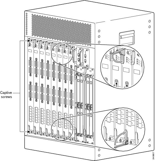
Step 1 Carefully align the upper and lower edges of the card with the upper and lower guides in the chassis.
Caution The Cisco cable interface line card weighs 11.6 lbs. Use both hands when handling the card. Do not drop the card or otherwise damage the carrier rails. Bent or damaged rails can damage the card guides and prevent line card installation. When installing cards for the first time, or when all the captive screws of the card are loose, insert cards first in slot 5/1 and work towards slot 8/0 to prevent uneven gasket pressure. Step 2 Slide the card into the slot until you can feel it seat in the backplane connectors. (See Figure 19.) Step 3 Close the ejector levers to secure the card in the backplane. (See Figure 20.) Step 4 Engage and begin tightening the captive screws first by hand. Then, use either a T-10 Torx (included in the line card accessory kit) or a common flathead screwdriver to tighten the captive screws between 5 to 7 in-lbs.
Caution Always tighten the captive screws on each line card, but not more than the maximum of 7 in-lbs. These screws prevent accidental removal and provide proper grounding for electromagnetic interference (EMI) shielding.
Note When fully inserted, the line card cycles through its power-on self-test, and the POWER and STATUS LEDs turn on. (If either of those LEDs is flashing, see Troubleshooting the Line Card Installation section).
Cabling the Line Card
The Cisco cable interface line card uses 75–ohm precision video coaxial cables and 75–ohm MCX connectors for the upstream connection to the RF Switch or HFC plant. The SFP modules are used to connect the GE ports for the downstream connection to the EQAM device.
The following procedures are for the customized RF cables and SFP modules, and for the maintenance of the Cisco preconfigured cable bundles.
Installing Cables
ProcedureCisco cables are color-coded for easy reference and installation. The cable color corresponds to a specific port on the card. Table 1 lists the cable ports and associated cable color applicable when using Cisco dual-shielded cables or quad-shielded cabling.
Note
Precision miniature video coaxial cables come in various colors and you can use any cable color combination. However, when you are connecting the Cisco cable interface line card to the Cisco RF Switch, we recommend that you install the cables in the UCH2 as listed in Table 1.
Table 4 Cisco Dual-shielded and Quad-shielded Cable Ports and Cable Colors Universal Cable Holder (1) RF Switch Header (1) Universal Cable Holder (2) RF Switch Header (2) Line Card Port Cable Color RF Switch Port Cable Color Line Card Port Cable Color RF Switch Port Cable Color US0 Red A Red US10 Red A Red US1 White B White US11 White B White US2 Blue C Blue US12 Blue C Blue US3 Green D Green US13 Green D Green US4 Yellow H Yellow US14 Yellow H Yellow US5 Violet I Violet US15 Violet I Violet US6 Orange J Orange US16 Orange J Orange US7 Black K Black US17 Black K Black US8 Gray E Gray US18 Gray E Gray US9 Brown L Brown US19 Brown L Brown
Note
The cable kits and cabling color scheme of the Cisco cable interface line card is different from the earlier line cards like the Cisco UBR-MC20X20V and Cisco uBR10-MC5X20S/U/H. However, you can also use legacy cable kits with the Cisco cable interface line card. For applicable color schemes and cabling information for legacy cable kits, refer to Cabling the Cisco uBR10-MC5X20S/U/H Cable Interface Line Card with UCH2 - Quick Start Guide.To replace cables or install new cables in a UCH2:
Caution
The UCH2 must be used for all cable connections to the line card. Failure to use a UCH2 may cause permanent damage to the line card connectors, resulting in low or no RF output in the downstream or upstream.
Note
Do not attempt to remove or install cables in the UCH2, when the UCH2 is attached to the faceplate.
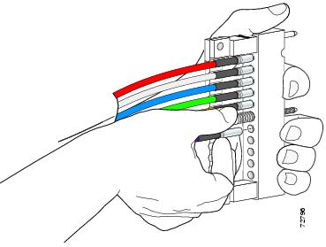
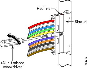
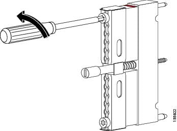
Step 1 Use the T-10 TORX driver tool to loosen the lock bar on the side where you want to install a cable. (See Figure 1.) Step 2 Use a flathead screwdriver as a lever to slide open the lock bar. (See Figure 2.) Step 3 Remove the ESD cap from a cable (see Figure 1 and Figure 2) and insert the cable into the hole in the UCH2. (See Figure 3.) Use Table 1 to determine the correct color and location for each colored cable. Step 4 Insert and wiggle the connector into the hole.
Note The cables fit loosely in the holes, and are not locked into place until the lock bar is closed in 6 Step 5 Repeat Step 3 and Step 4 for the remaining cables you are installing.
Note Ensure the cables are aligned correctly and inserted completely or the slide bar will not close. Step 6 Slide the lock bar close completely in the UCH2, and use the T-10 TORX driver tool to tighten the screws clockwise (torque 10 in-lbs, 1.13 Newton meters [Nm]).
Note Clamp bar maximum torque is 15 in-lbs (1.70Nm).
Installing the UCH2
ProcedureAfter the cables are installed in the UCH2, perform the following steps to install UCH2 on the line card:
Note
Before proceeding, remove the protective sticker covering the line card DS ports.
Caution
Ensure that you are properly grounded with an ESD-preventative ground strap.
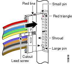
Step 1 Attach a jumper cable to the ground point on the chassis. Step 2 Briefly touch the center of each cable connector with the jumper cable to remove any built-up ESD potential. Step 3 Position the UCH2 so that the red line is on the same side as the red triangle on the faceplate. See Figure 1. Step 4 Align the end pins with the pin holes in the faceplate of the line card, and guide the UCH2 onto the faceplate. Step 5 Hold the cables and UCH2 in place while tightening the lead screw with your fingers. Do not bend the cables at right angles. Step 6 Use the flathead screwdriver to tighten the lead screw to 10 in–lbs (maximum torque 15 in-lbs).
Caution Torquing the lead screw to more than the maximum of 20 in-lbs can cause the lead screw to fail.
Installing the SFP Module on the Line Card
ProcedureTo insert an SFP transceiver module into the GE interface port of the Cisco cable interface line card:
Caution
Ensure that you are properly grounded with an ESD-preventative ground strap.
Step 1 Remove the SFP transceiver module from its protective packaging. Step 2 Find the transmit (Tx) and receive (Rx) markings that identify the top side of the SFP transceiver module.
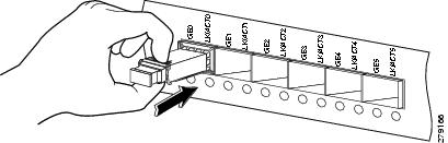
Note On some SFP transceivers, the Tx and Rx markings might be replaced by arrowheads pointing from the SFP transceiver connector (transmit direction or Tx) and towards the connector (receive direction or Rx). Step 3 Position the SFP transceiver module in front of the socket opening. Step 4 Insert the SFP transceiver module into the socket until you feel the SFP module connector snap into the socket connector (See Figure 23), and close the SFP latch. Step 5 Remove the dust cap from the SFP transceiver module and save for future use. Step 6 Inspect and clean the LC connector fiber-optic end-faces. Step 7 Remove the dust plugs from the SFP transceiver optical bores.
SFP Module Interface Cables
After installing the SFP module in the GE port, you must attach the cables to the SFP module. The connector types used to attach interface cables to the SFP Module are given below:
RJ-45 Connector
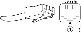
The RJ-45 connector, shown in Figure 1, is used to provide full-duplex GE connectivity to high-end workstations and between wiring closets over an existing copper network infrastructure.
SC Fiber-Optic Connector
The SC Fiber-Optic connector, shown in Figure 1, is used to connect fiber-optic module ports or transceivers with the external SMF or MMF network.
Note
Ensure that the optical connectors are clean before making the connections. Contaminated connectors can damage the fiber and cause data errors.
Note
Always insert the network connector completely into the socket. A secure connection is especially important when you are establishing a connection between a module and a long distance (1.24 miles or 2 km) network or a module and a highly attenuated network. If the link LED does not light up, try removing the network cable plug and reinserting it firmly into the module socket. It is possible that dirt or skin oils have accumulated on the plug faceplate (around the optical-fiber openings) generating significant attenuation and reducing the optical power levels below threshold levels so that a link cannot be made.LC Fiber-Optic Connector
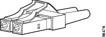
The LC fiber-optic connector, shown in Figure 1, is a small form-factor fiber-optic connector that provides high density fiber connectivity. The line card connector can be used with either MMF or SMF cables. The line card connector uses a latching clip mechanism that is similar to the one used on the RJ-45 copper connector.
Note
Ensure that the optical connectors are clean before making the connections. Contaminated connectors can damage the fiber and cause data errors.Connecting a Network Cable to an SFP Module
Procedure
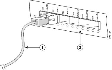
Step 1 Insert the network cable (RJ-45 Connector, SC Fiber-Optic Connector, or LC Fiber-Optic Connector) into the SFP module port, and listen for the click sound to ensure proper seating. (See Figure 1.) Step 2 Pull the network cable gently outwards to ensure that the cable connector is firmly in place. Step 3 Insert the other end of the network cable into the receptacle of the EQAM device.
Removing the Line Card
Shut down the card interface before removing the card from the chassis. For information about shutting down and restarting the interface, refer to the “Shutting Down and Restarting the Interface” in the Cisco uBR10012 Software Configuration Guide.
If the maintenance LED is on, you can remove the card without affecting system operations.
This section describes how to remove the Cisco cable interface line card from the chassis.
Removing the UCH2
ProcedureTo remove the UCH2 from the Cisco cable interface line card:
Caution
Ensure that you are properly grounded with an ESD-preventative ground strap.
Step 1 Loosen the lead screw (counterclockwise) on the UCH2 until it is completely disengaged from the faceplate. See Figure 1 Step 2 Pull the UCH2 straight away from the faceplate using the lead screw.
Caution Do not use the cables to pull the holder from the faceplate. Be careful not to bend the cables at right angles to the holder.
Removing Cables
Procedure
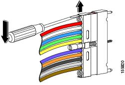
Step 1 Use the T-10 TORX driver tool to loosen the UCH2 lock bar on the side from where you want to remove the cable. (See Figure 1.) Step 2 Slide open the lock bar by hand, or with a flathead screwdriver if the bar is tight or hard to access. (See Figure 2.) Step 3 Carefully pull the cable completely out of the UCH2.
Caution Be careful not to bend the cables at right angles.
Note If the cable does not come loose from the UCH2, make sure the lock bar is completely open. Step 4 Repeat Step 1 to Step 3 for each cable you are removing.
Removing the Line Card
Procedure
Removing the SFP Module From the Line Card
Procedure
Step 1 Disconnect the network cable from the SFP module connector. For optical SFP transceivers, immediately reinstall the dust plugs in the SFP transceiver optical bores. Step 2 Unlock and remove the SFP module from the socket connector.
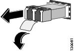
- If the SFP transceiver has a Mylar tab latch, pull the tab gently in a slightly downward direction until the transceiver disengages from the socket connector, and then pull the SFP transceiver straight out of the socket. Do not twist or pull the Mylar tab as you could detach it from the SFP transceiver. (See Figure 1.)
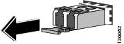
- If the SFP transceiver has an actuator button latch, gently press the actuator button on the front of the SFP transceiver until it clicks and the latch mechanism releases the SFP transceiver from the socket connector. Grasp the actuator button between your thumb and index finger, and carefully pull the SFP transceiver straight from the module slot. (See Figure 2.)
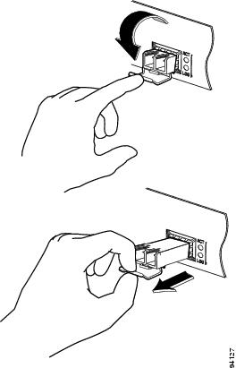
- If the SFP transceiver has a bale-clasp latch, pull the bale out and down to eject the SFP transceiver from the socket connector. If the bale-clasp latch is obstructed and you cannot use your index finger to open it, use a small, flat-blade screwdriver or a long narrow instrument to open the bale-clasp latch. Grasp the SFP transceiver between your thumb and index finger, and carefully remove it from the socket. (See Figure 3.)
Step 3 Place the removed SFP module in an antistatic bag.
Troubleshooting the Line Card Installation
If the Cisco cable interface line card is not working properly, check the following:
- Verify that the LEDs (see Table 1 for LED description) light up and go through the power on self test (POST) when the card is inserted in the chassis.
- Verify that the UCH2 is securely in place on the faceplate. Check that the lead screw is secure.
Note
The recommended maximum torque for a lead screw is 15 in-lbs (1.69 Nm).
Note
Use the MCX to F connector adapter to easily adapt the MCX connection for testing the cables.- Verify that the lock bar on the UCH2 is in place and tightened.
- Verify that the correct level of software licensing is available for the card.
Table 5 Cisco Line Card LEDs LED Status Description POWER Green
Off
Card is powered on.
Card is not powered on.
STATUS Green
Yellow
Off
Processor has booted and passed diagnostics, or is on standby.
In bootup mode.
No power to the line card.
MAINT Yellow
Off
It is safe to remove the line card.
No action necessary.
US0 through US19 Green
Off
Upstream-enabled path is configured and able to pass traffic.
Upstream port is not enabled.
GE0 through GE5 Green
Off
DEPI port is configured and able to pass traffic.
DEPI port is not enabled.
LK/ACT0-LK/ACT5 Green (steady)
Green (blinking)
Off
Port is enabled; the link is working, and there is no US or DS traffic activity.
Port is enabled; the link is working, and there is US or DS traffic activity.
Ethernet link is not working.
Front Panel Display — Number of licenses for US and DS channels (See Table 1 for license information) Technical Specifications and Component Part Numbers
The following tables provide technical specifications and part number information for the Cisco cable interface line card.
Part Numbers
Table 1 lists the part numbers for the Cisco cable interface line card, cable kits, cables, connectors, tubing, and tools.
Table 6 Part Numbers Description Part Numbers
Universal Cable Holder (UCH)
Cable Bundles
- Cable bundle for RF card to HFC plant—Two UCH2 units attached to one end and 20 F connectors attached to the other end, 9.84 feet (3 m) long.
- Cable bundle for RF card to RF Switch—2 UCH2 units attached to one end and 2 RF Switch header blocks attached to the other end, 3.2 feet (1 m) long.
- Cable bundle for RF switch to HFC plant—2 RF Switch header blocks attached to one end and 20 F connectors attached to the other end, 9.84 feet (3 m) long.
RF Switch header blocks for MCX connectors, qty 2 pcs CAB-RFSW-MULT-HB Small Form-Factor Pluggable (SFP)
MCX fixed pin connector
75–ohm precision miniature video cable
MCX connector strip tool
MCX connector to F connector adapter PN-53140137, White Sands Engineering F connector strip tool
MCX and F connector crimper tool PN-ACT- 483, White Sands Engineering F connector
Shrink tubing
- Size—1/4 inch
- Shrink ratio—2:1
- Recovered wall thickness—0.025 inch
- Inside diameter after recovery—0.125 inch
Note Do not use shrink tubing with Cisco quad-shielded cables. — Physical Specifications and Compliance Information
Table 6 lists the physical specifications for the Cisco uBR-MC3GX60V cable interface line card.
Table 7 Cisco Cable Interface Line Card Specifications Description Specification Card Dimensions Weight 11.6 lb (5.26 kg) Power Consumption
246W5 (839 BTU/hr6) Thermal Heat Dissipation
246W (839 BTU/hr) Mean Time Between Failure (MTBF)
Supports 5 9s availability. 100,748 hours Temperature Range Relative Humidity Operating Altitude -196 to 13,123 ft. (-60 to 4000 m) Standards, Compliance, Protocols
Software Requirements
Cisco IOS Release 12.2(33)SCE or a later release 5 W = Watts6 BTU/hr = British thermal units per hourRelated Documentation
For more information about the Cisco cable interface line cards, Cisco uBR10012 universal broadband router chassis, and software configuration, see the following documents:
- Configuring the Cisco Cable Interface Line Card http://www.cisco.com/en/US/docs/interfaces_modules/cable/broadband_processing_engines/ubr_mc3gx60v/configuration/guide/mc3g60_cfg.html
- Cisco uBR10012 Universal Broadband Router Hardware Installation Guide http://www.cisco.com/en/US/docs/cable/cmts/ubr10012/installation/guide/hig.html
- Cisco uBR10000 Series Universal Broadband Router Release Notes http://www.cisco.com/en/US/products/hw/cable/ps2209/prod_release_notes_list.html
- Cisco uBR10012 Router Software Features http://www.cisco.com/en/US/products/hw/cable/ps2209/products_feature_guides_list.html
- Cisco uBR10012 Universal Broadband Router Software Configuration Guide http://www.cisco.com/en/US/docs/cable/cmts/ubr10012/configuration/guide/scg.html
- Cisco IOS CMTS Cable Software Configuration Guide, Release 12.2SC
- Cisco IOS CMTS Cable Command Reference http://www.cisco.com/en/US/docs/ios/cable/command/reference/cbl_book.html
Obtaining Documentation and Submitting a Service Request
For information on obtaining documentation, submitting a service request, and gathering additional information, see the monthly What’s New in Cisco Product Documentation, which also lists all new and revised Cisco technical documentation, at: http://www.cisco.com/en/US/docs/general/whatsnew/whatsnew.html
Subscribe to the What’s New in Cisco Product Documentation as a Really Simple Syndication (RSS) feed and set content to be delivered directly to your desktop using a reader application. The RSS feeds are a free service and Cisco currently supports RSS Version 2.0.
Cisco and the Cisco logo are trademarks or registered trademarks of Cisco and/or its affiliates in the U.S. and other countries. To view a list of Cisco trademarks, go to this URL: http://www.cisco.com/go/trademarks. Third-party trademarks mentioned are the property of their respective owners. The use of the word partner does not imply a partnership relationship between Cisco and any other company. (1110R)
Copyright © 2012, Cisco Systems, Inc. All rights reserved.


 Feedback