Cisco APIC M1/M2/M3/L1/L2/L3 to M4/L4 Cluster Migration, Release 6.0(2)
Available Languages
Bias-Free Language
The documentation set for this product strives to use bias-free language. For the purposes of this documentation set, bias-free is defined as language that does not imply discrimination based on age, disability, gender, racial identity, ethnic identity, sexual orientation, socioeconomic status, and intersectionality. Exceptions may be present in the documentation due to language that is hardcoded in the user interfaces of the product software, language used based on RFP documentation, or language that is used by a referenced third-party product. Learn more about how Cisco is using Inclusive Language.
- US/Canada 800-553-2447
- Worldwide Support Phone Numbers
- All Tools
 Feedback
 Feedback
Guidelines and Limitations for Migrating Cisco APIC Servers
Replacing the In-service Cisco APIC Servers
Replacing APIC Servers with APIC Servers Running a Different Software Release
Commissioning APIC Servers Without CIMC Connections
Decommissioning the Standby Cisco APIC Servers to be Replaced by a Normal Cluster
This document provides details on how to perform an in-service replacement of older generation Cisco APIC servers with the L4/M4 model. As announced on cisco.com[1], the Cisco APIC L1/M1 and L2/M2 servers have reached their end-of-sale and end-of-life date. At the time of this writing, the suggested Cisco APIC server replacement is Cisco APIC L4/M4.
Note: This document is for the Cisco APIC 6.0(2) and later releases. For cluster migration information for the 5.3 releases, see Cisco APIC M1/M2/M3/L1/L2/L3 to M4/L4 Cluster Migration, Release 5.3(1).
The Cisco APIC L4/M4 requires the Cisco APIC software 5.3(1) release or later or the 6.0(2) release or later. This document uses the Cisco APIC M4/L4 and Cisco APIC 6.0(2h) release as an example. Cisco APIC servers forming a cluster must all run the same software release. You cannot have different software releases inside one cluster; doing so will result in the cluster not converging. There is one exception to this rule: during a software upgrade process, there will be a temporary divergence in software releases within the cluster. This means that before you attempt to replace the existing Cisco APIC M1/L1, M2/L2, or M3/L3 server with a Cisco APIC M4/L4 server, you must bring the running cluster to a supported release.
To determine which release you are currently running on the Cisco APIC server, power on your M4/L4. Cisco APIC M4/L4 servers shipping at the time of this writing are shipped with Cisco APIC release 6.0(2h).
Cisco APIC release 6.0(2) and later supports Auto Firmware Update when replacing or installing a new APIC. With this feature, any new APIC is automatically upgraded to the release of the other APICs in the cluster.
You can mix Cisco APIC M1/L1, M2/L2, M3/L3, and M4/L4 using any possible combination. There are no restrictions other than the minimum software release mentioned in the Software Release Requirements.
Table 1. Table Caption
|
|
APIC-M1/L1 |
APIC-M2/L2 |
APIC-M3/L3 |
APIC-M4/L4 |
| APIC-M1/L1 |
X
|
X
|
X
|
x
|
| APIC-M2/L2 |
X
|
X
|
X
|
X
|
| APIC-M3/L3 |
X
|
X
|
X
|
X
|
| APIC-M4/L4 |
X
|
X
|
X
|
X
|
When a cluster has a mix of hardware models, its performance aligns to the lowest common denominator. For example, a Cisco APIC-M2 cluster scales up to 1000 edge ports while an APIC-M3 cluster increases that number to 1200[2].
Guidelines and Limitations for Migrating Cisco APIC Servers
● The Cisco APIC L1/M1 server is no longer supported. However, you can still use the procedures in this document to migrate Cisco APIC L1/M1 servers to a newer server model.
● When you decommission a Cisco APIC, the APIC loses all fault, event, and audit log history that was stored in it. If you replace all Cisco APICs, you lose all log history. Before you migrate a Cisco APIC, we recommend that you manually backup the log history.
● Do not decommission more than one Cisco APIC at a time.
● Wait until the cluster reaches the fully fit state before proceeding with a new replacement.
● Do not leave a decommissioned Cisco APIC powered on.
Replacing the In-service Cisco APIC Servers
This section describes how to replace a Cisco APIC cluster on every existing M1/L1, M2/L2, or M3/L3 server with an M4/L4 server model in service with no impact to the data plane nor the control plane. The procedure is fully supported by Cisco. This procedure focuses on a 3-node Cisco APIC cluster and the process is similar for larger clusters.
Procedure
Step 1. Validate that the existing cluster is fully-fit.
Ensure your existing cluster is fully fit before attempting this procedure. You must not upgrade or modify a Cisco APIC cluster that is not fully fit. To verify that your existing cluster is fully fit:
a. In the menu bar, choose System > Controllers.
b. In the Navigation pane, expand Controllers and choose any Cisco APIC.
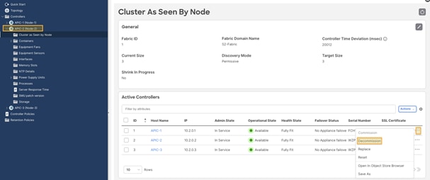
c. Expand the Cisco APIC and choose Cluster as seen by node.
Figure 1
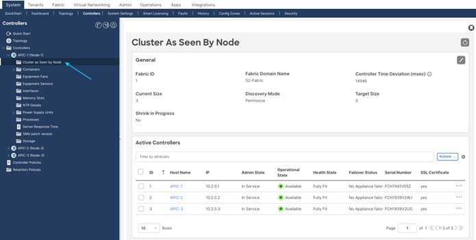
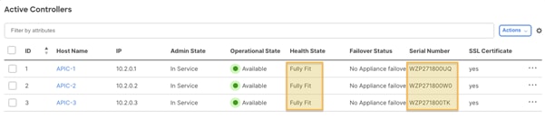
d. Check the operational state of all nodes. The nodes must be "Available" and the health state must be "Fully Fit."
e. In Figure 2, Figure 3, and Figure 4, the initial cluster contains three Cisco APIC M2s.
Figure 2
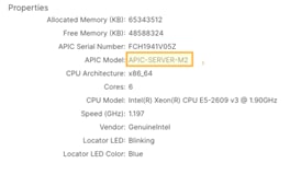
Figure 3
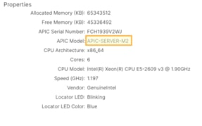
Figure 4
Step 2. Cable the replacement Cisco APIC M4/L4 servers.
In this scenario, you are replacing all three Cisco APIC M2 servers with Cisco APIC M4 servers. The process is the same as when replacing four, five, six, or seven servers. Physically install the replacement servers in the data center and cable them to the existing Cisco ACI fabric as you would with any server. Cable the Out-of-band (OOB) management connection. There is no need to set aside new IP addresses for the replacement Cisco APIC servers, because each Cisco APIC will simply take over the IP address of the server it is replacing.
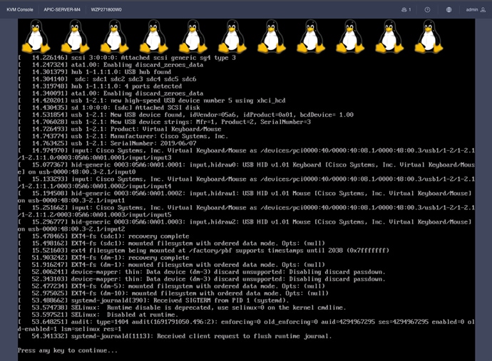
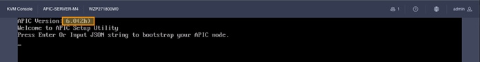
Step 3. Power up the Cisco APIC M4/L4 server that will replace an existing Cisco APIC server.
Bring up a Serial over LAN (SoL), vKVM console connection, or physical VGA connection so you can monitor their boot process. After a few minutes, you will be prompted to press any key to continue. Pressing any key at the prompt will show the APIC release installed on the M4/L4 server.
Figure 5
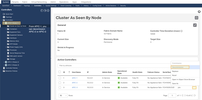
Step 4. Decommission Cisco APIC 3 (or the highest number APIC in the cluster).
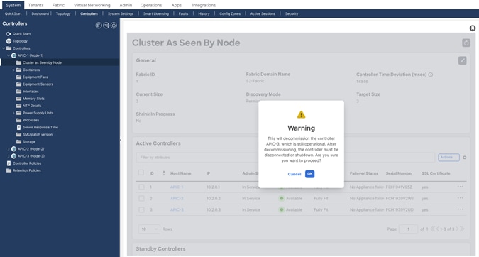
From Cisco APIC number 1 or 2, within the "cluster as seen by node" view (Figure 6), decommission the last Cisco APIC by right-clicking on that Cisco APIC and choosing Decommission as shown in Figure 6.
Figure 6
After choosing Decommission, you are prompted to confirm the selection. A message displays instructing you to disconnect or power down the APIC after decommissioning it.
Figure 7
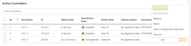
After decommissioning the APIC, the GUI shows the APIC as "Out of Service" and "Unregisitered."
Figure 8

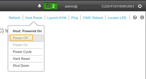
Wait roughly 5 minutes, then log into that Cisco APIC's CIMC to initiate a power off sequence or use the server power off button to power off the server after having decommissioned the Cisco APIC server. You will see the status change from "In Service" to "Out of Service."
You can power off the Cisco APIC from the CIMC GUI or CLI. The example in Figure 9 shows powering off the Cisco APIC from the CIMC GUI.
Figure 9
Step 5. Register the new Cisco APIC for the cluster membership.
Cisco APIC release 6.0(2) and later allows you to replace a Cisco APIC server directly from the GUI, as long as the APIC has access to the replacement APIC server's CIMC. You do not need to perform any bootstrapping of the replacement server from the server console.
The commission step bootstraps the replacement M4/L4 APIC with the following settings:
● CIMC Address
● CIMC username
● CIMC password
● APIC Name (this will be pre-populated when doing commission)
● Admin Password: (cluster password)
● Controller ID: (this will be pre-populated when doing commission)
● Pod-ID
● Serial Number: (will be discovered automatically when APIC connects to CIMC)
● Out-of-Band Address
● Out-of-Band gateway
● On the APIC server that was decommissioned, Right-click on the server and select commission.
Figure 10
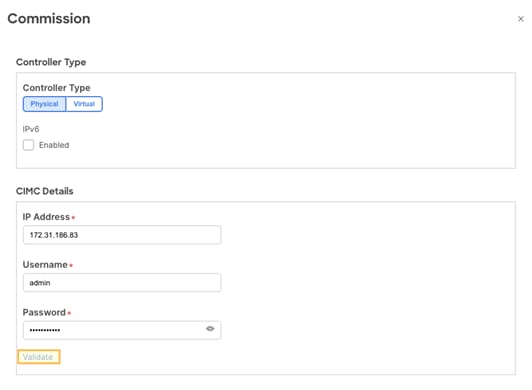
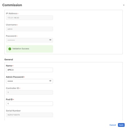
Step 6. Enter the APIC-M4 CIMC address and login credentials and click Validate:
Figure 11
After successful validation, complete the General section:
Figure 12
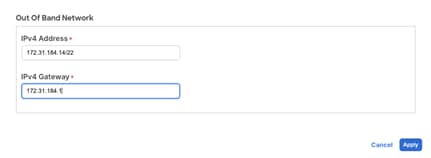
Enter the out-of-band IP address. The out-of-band address should be the same as the decommissioned APIC M2.
Figure 13
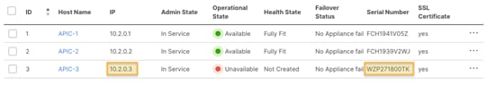
Step 7. Verify cluster membership.
After approximately 5 minutes, you will observe transitions in the operational state and health status. First, you may see the infra IP address configured on the new server. The new server serial number will be populated.
Figure 14
Shortly after, the new server's operational state will change to Available. The health state may show "Data Layer Partially Diverged."
Figure 15

APIC 1 and 2 may also transition to the "Diverged" state during cluster synchronization.
Figure 16

Wait until all APICs are stable and the health state is "Fully Fit."
Figure 17
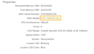
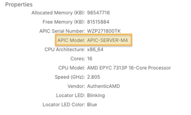
If you zoom in on the new server's properties, you will see it is indeed an M4/L4 with a new serial number:
Figure 18
Step 8. Decommission another server.
To decommission another server, repeat steps 4 through 7. Remember that to decommission a server, you need to perform the operation from another server. If you are logged into APIC-1 for example, do not decommission APIC-1. Log into APIC-2, go to the "Cluster As Seen By Node" view for APIC-2 and decommission APIC-1. This is shown below:
Figure 19
Do not forget to power off the server that you decommissioned before attempting to bring in a replacement.
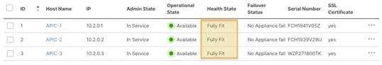
Step 9. Verify the entire cluster.
After replacing all APICs with APIC-M4s, validate that the entire cluster is fully fit:
Figure 20
At this point, you have a fully operational, fully-fit Cisco APIC cluster with new hardware.
Replacing APIC Servers with APIC Servers Running a Different Software Release
Beginning with Cisco APIC release 6.0(2), APIC servers being commissioned to the cluster can be running a different software release than the cluster. The replacement procedure described in the previous section is the same when the replacement APIC server is running a different software release. You must download the APIC ISO image for the currently installed release to the APIC cluster prior to executing the migration procedure.
Figure 21
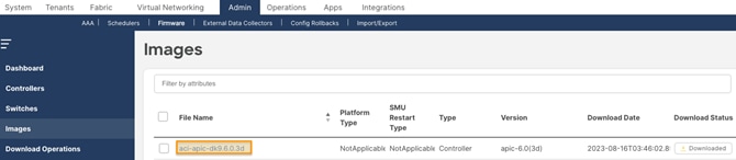
When executing the APIC server migration with APICs running a different software release, it will take longer for the commission step to execute. This step can take more than 30 minutes to be executed. During this time, the APIC cluster state will not update and the replacement server out-of-band management IP address will be unavailable.
Commissioning APIC Servers Without CIMC Connections
Cisco APIC release 6.0(2) and later supports bootstrapping and replacing APICs from the GUI. This simplifies the commission process and removes the requirement to execute the bootstrap configuration directly on the server console.
You cannot use the Cisco APIC GUI bootstrapping procedure if the CIMC address is not reachable from the APIC management address on TCP port 22 or the CIMC is not connected to the network. The examples in this section show how to bootstrap the APIC from the CIMC console or using a REST API POST operation to the APIC management address.
If the replacement APIC server is configured with a CIMC IP address but does not have connectivity to the APIC management address on TCP port 22, you can use the procedure in this section to paste the JSON payload directly to the APIC console using KVM or Serial over LAN (SoL).
The following example JSON string is for a 3-node cluster. Add attitional nodes as required.
{
"cluster": {
"fabricName": "<fabric_name>",
"fabricId": 1,
"clusterSize": 3,
"layer3": false,
"gipoPool": "225.0.0.0/15",
"adminPassword": "<password>",
"infraVlan": <infra VLAN ID>
},
"nodes": [{
"nodeName": "<node_name>",
"controllerType": "physical",
"serialNumber": "<serial_number>",
"nodeId": 1,
"podId": 1,
"cimc": {
"address4": "<ip_address>",
"username": "admin",
"password": "<password>"
},
"oobNetwork": {
"address4": "<ip_address>",
"gateway4": "<gateway_address>",
"enableIPv4": true,
"enableIPv6": false,
"address6": "",
"gateway6": ""
}
}, {
"nodeName": "<node_name>",
"controllerType": "physical",
"serialNumber": "<serial_number>",
"nodeId": 2,
"podId": 1,
"cimc": {
"address4": "ip_address",
"username": "admin",
"password": "<password>"
},
"oobNetwork": {
"address4": "<ip_address>",
"gateway4": "<gateway_address>",
"enableIPv4": true,
"enableIPv6": false,
"address6": "",
"gateway6": ""
}
}, {
"nodeName": "<node_name>",
"controllerType": "physical",
"serialNumber": "<serial_number>",
"nodeId": 3,
"podId": 1,
"cimc": {
"address4": "<ip_address>",
"username": "admin",
"password": "<password>"
},
"oobNetwork": {
"address4": "<ip_address>",
"gateway4": "<gateway_address>",
"enableIPv4": true,
"enableIPv6": false,
"address6": "",
"gateway6": ""
}
}],
"pods": [{
"podId": 1,
"tepPool": "10.0.0.0/16"
}]
}
The following example procedure commissions APIC-1 using the values in the previous section by pasting directly to the APIC console through the CIMC.
Procedure
Step 1. Post the following JSON string directly on the APIC-M4 vKVM console that will be commissioned as APIC-1. The JSON post should include all APICs in the cluster in the nodes section.
{
"cluster": {
"fabricName": "S2-Fabric",
"fabricId": 1,
"clusterSize": 3,
"layer3": false,
"gipoPool": "225.0.0.0/15",
"adminPassword": "<cluster password>",
"infraVlan": 3914
},
"nodes": [{
"nodeName": "APIC-1",
"controllerType": "physical",
"serialNumber": "WZP271800UQ",
"nodeId": 1,
"podId": 1,
"cimc": {
"address4": "172.31.186.87",
"username": "admin",
"password": "<CIMC password>"
},
"oobNetwork": {
"address4": "172.31.184.12/22",
"gateway4": "172.31.184.1",
"enableIPv4": true,
"enableIPv6": false,
"address6": "",
"gateway6": ""
}
}, {
"nodeName": "APIC-2",
"controllerType": "physical",
"serialNumber": "WZP271800W0",
"nodeId": 2,
"podId": 1,
"cimc": {
"address4": "172.31.186.85",
"username": "admin",
"password": "<CIMC password>"
},
"oobNetwork": {
"address4": "172.31.184.13/22",
"gateway4": "172.31.184.1",
"enableIPv4": true,
"enableIPv6": false,
"address6": "",
"gateway6": ""
}
}, {
"nodeName": "APIC-3",
"controllerType": "physical",
"serialNumber": "WZP271800TK",
"nodeId": 3,
"podId": 1,
"cimc": {
"address4": "172.31.186.83",
"username": "admin",
"password": "<CIMC password>"
},
"oobNetwork": {
"address4": "172.31.184.14/22",
"gateway4": "172.31.184.1",
"enableIPv4": true,
"enableIPv6": false,
"address6": "",
"gateway6": ""
}
}],
"pods": [{
"podId": 1,
"tepPool": "10.2.0.0/16"
}]
}
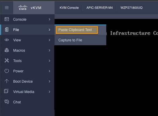
Choose File > Paste Clipboard Text on the vKVM console.
Figure 22
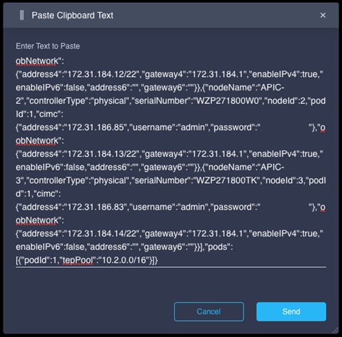
Paste the JSON text string into the window. The JSON text must be in a single line. If you use the examples in this document, make sure to format the JSON string as a single line.
Figure 23
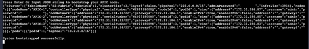
The JSON string will be pasted into the vKVM console. Hit enter to to complete the boostrap from the vKVM console.
Figure 24
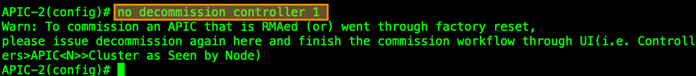
Step 2. Commission APIC-1 from APIC-2 or APIC-3 from the APIC CLI.
APIC-1 must be commissioned from APIC-2 or APIC-3. Commissioning the APIC from the GUI will require a CIMC connection. To commission the APIC without a CIMC connection, use the APIC CLI.
The APIC displays a warning informing you to use the GUI, but will accept the CLI command.
Figure 25
If the CIMC is not connected to the network, you can use a REST API POST operation to post the JSON payload to the APIC management address. This requires that you configure the APIC management address and password from the APIC console.
The following example shows the POST operation and payload:
<apic1>/api/workflows/v1/cluster/bootstrap
{
"version": 1,
"cluster": {
"fabricName": "S2-Fabric",
"fabricId": 1,
"clusterSize": 3,
"infraVlan": 3914,
"gipoPool": "225.0.0.0/15",
"adminPassword": "<cluster password>"
},
"nodes": [
{
"controllerType": "physical",
"serialNumber": "WZP271800UQ",
"nodeId": 1,
"nodeName": "APIC-1",
"podId": 1,
"oobNetwork": {
"enableIPv4": true,
"address4": "172.31.184.12/22",
"gateway4": "172.31.184.1"
},
"cimc": {
"address4": "0.0.0.0",
"username": "admin",
"password": "<any string>"
}
},
{
"controllerType": "physical",
"serialNumber": "WZP271800W0",
"nodeId": 2,
"nodeName": "APIC-2",
"podId": 1,
"oobNetwork": {
"enableIPv4": true,
"address4": "172.31.184.13/22",
"gateway4": "172.31.184.1"
},
"cimc": {
"address4": "0.0.0.0",
"username": "admin",
"password": "<any string>"
}
},
{
"controllerType": "physical",
"serialNumber": "WZP271800TK",
"nodeId": 3,
"nodeName": "APIC-3",
"podId": 1,
"oobNetwork": {
"enableIPv4": true,
"address4": "172.31.184.14/22",
"gateway4": "172.31.184.1",
"mode": "auto"
},
"cimc": {
"address4": "0.0.0.0",
"username": "admin",
"password": "<any string>"
}
}
],
"pods": [
{
"podId": 1,
"tepPool": "10.2.0.0/16"
}
]
}
Recommissioning the APIC can also be done using a REST API POST operation. The following example shows the REST API POST operation for commissioning APIC 1 from APIC 2:
<apic2>/api/mo/topology/pod-1/node-1/av.json
{
"infraWiNode": {
"attributes": {
"dn": "topology/pod-1/node-1/av/node-1",
"adminSt": "in-service"
},
"children": []
}
}
Decommissioning the Standby Cisco APIC Servers to be Replaced by a Normal Cluster
If your cluster contains obsolete standby Cisco APIC servers, the same process applies. When you bring your existing cluster to a supported release, the standby Cisco APIC servers are automatically upgraded.
Procedure
Step 1. Decommission the standby Cisco APIC to be replaced to a normal cluster member. Power it down and wait enough time for the controller to become unregistered. Wait at least 1 hour after powering down the standby APIC for it to be erased from the database. Alternatively, you can execute the following command on any APIC in the cluster to erase the entry:
acidiag cluster erase standby_node_id standby_serial_number
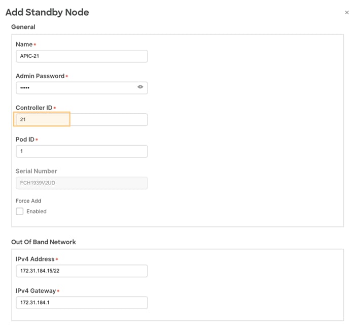
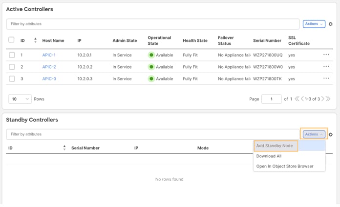
Step 2. Add the new M4/L4 APICs as Standby.
Figure 26
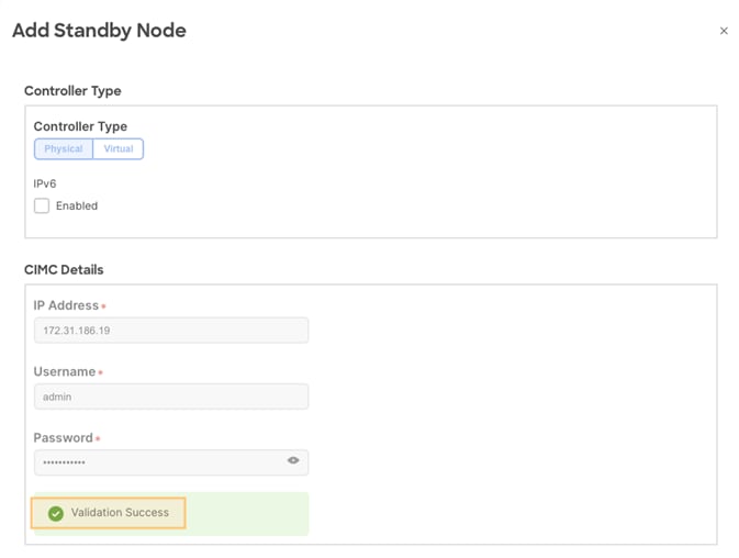
Step 3. Add and validate CIMC information for the Standby APIC.
Figure 27
Step 4. Add the APIC and out-of-band addresses. Standby APICs will be numbered between 21 to 29.
Figure 28