
Cisco ACI CloudSec Encryption

Cisco ACI CloudSec has been deprecated starting with the ACI 6.0.2 release, and has been removed from Cisco ACI releases 6.2(2) and later. We recommend that you use MACSec as the encryption method between sites instead. See Nexus Dashboard Orchestrator Fabric Management Templates for ACI Fabrics for more information.
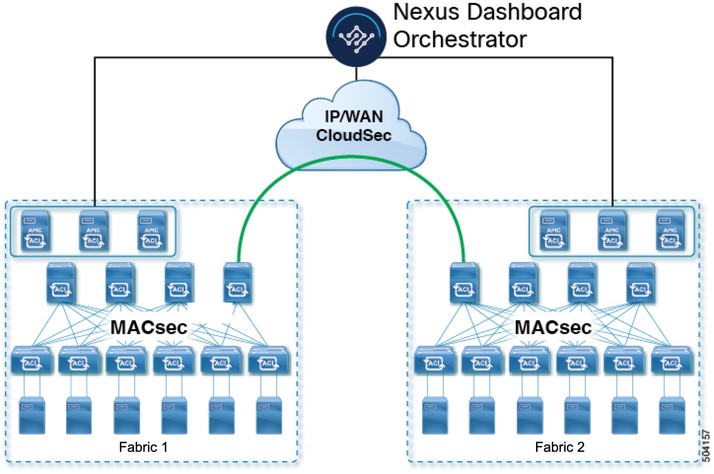
As most Cisco ACI deployments are adopting the Multi-Site architecture to address disaster recovery and scale, the current security implementation using MACsec encryption within local site is becoming insufficient to guarantee data security and integrity across multiple sites connected by insecure external IP networks interconnecting separate fabrics. Nexus Dashboard Orchestrator Release 2.0(1) introduces the CloudSec Encryption feature designed to provide inter-site encryption of traffic.
Multi-Site topology uses three tunnel end-point (TEP) IP addresses (Overlay Multicast TEP, Overlay Unicast TEP, and External TEP Pool) to provide connectivity between sites. These TEP addresses are configured by the admin on Nexus Dashboard Orchestrator and pushed down to each site’s Cisco APIC, which in turn configures them on the spine switches. These three addresses are used to determine when traffic is destined for a remote site, in which case an encrypted CloudSec tunnel is created between the two spine switches that provide physical connectivity between the two sites through the Inter-Site Network (ISN).
The following figure illustrates the overall encryption approach that combines MACsec for local site traffic and CloudSec for inter-site traffic encryption.
Requirements and Guidelines
When configuring CloudSec encryption, the following guidelines apply:
-
CloudSec has been validated using a Nexus 9000 Inter-Site Network (ISN) infrastructure. If your ISN infrastructure is made up of different devices, or the devices are unknown (such as in the case of circuits purchased from a service provider), it is required that an ASR1K router is the first hop device directly connected to the ACI spine (with a separate pair of ASR1K devices deployed in each site), or the Nexus 9000 ISN network. The ASR1K router with padding-fixup enabled allows the CloudSec traffic to traverse any IP network between the sites.
To configure an ASR1K router:
-
Log in to the device.
-
Configure the UDP ports.
If you are running Release 3.7(1) or later and configure CloudSec to use the IANA-assigned port
8017, specify that port in the following command instead.
ASR1K(config)# platform cloudsec padding-fixup dst-udp-port*9999* -
Verify the configuration.
In the following output, ensure that the port you configured in the previous step (
8017or9999) is shown.ASR1K# show platform software ip rp active cloudsec CloudSec Debug: disabled CloudSec UDP destination port: enabled 1st UDP destination port: *9999* 2nd UDP destination port: 0 3rd UDP destination port: 0 ASR1K# show platform software ip fp active cloudsec CloudSec Debug: disabled CloudSec UDP destination port: enabled 1st UDP destination port: *9999* 2nd UDP destination port: 0 3rd UDP destination port: 0
-
-
If one or more spine switches are down when you attempt to disable CloudSec encryption, the disable process will not complete on those switches until the switches are up. This may result in packet drops on the switches when they come back up.
We recommend you ensure that all spine switches in the fabric are up or completely decommissioned before enabling or disabling CloudSec encryption.
-
Beginning with Nexus Dashboard Orchestrator, Release 3.7(1), CloudSec encryption can be configured to use the IANA-assigned port.
By default, CloudSec uses a proprietary UDP port. Orchestrator releases 3.7(1) or later can be configured to use the official IANA-reserved port
8017for CloudSec encryption between sites instead.
The IANA-reserved port is supported for Cisco APIC sites running release 5.2(4) or later.
To change this setting, CloudSec must be disabled on all sites. If you want to enable IANA reserved port, but already have CloudSec encryption enabled for one or more of your sites, disable CloudSec for all sites, enable IANA Reserve UDP Port option, then re-enable CloudSec for the required sites.
-
The CloudSec Encryption feature is not supported with the following features:
-
Precision Time Protocol (PTP)
-
Remote Leaf Direct
-
Virtual Pod (vPOD)
-
SDA
-
Remote Leaf or Multi-Pod configurations
-
Intersite L3Out, if the sites are running Cisco APIC releases prior to 5.2(4).
CloudSec is supported with intersite L3Out for APIC sites running release 5.2(4) or later.
-
Requirements
The CloudSec encryption capability requires the following:
-
Cisco ACI spine-leaf architecture with a Cisco APIC cluster for each site
-
Cisco Nexus Dashboard Orchestrator to manage each site
-
One Advantage or Premier license per each device (leaf only) in the fabric
-
An add-on license ACI-SEC-XF per device for encryption if the device is a fixed spine
-
An add-on license ACI-SEC-XM per device for encryption if the device is a modular spine
The following table provides the hardware platforms and the port ranges that are capable of CloudSec encryption.
| Hardware Platform | Port Range |
|---|---|
|
N9K-C9364C spine switches |
Ports 49-64 |
|
N9K-C9332C spine switches |
Ports 25-32 |
|
N9K-X9736C-FX line cards |
Ports 29-36 |
If CloudSec is enabled for a site, but the encryption is not supported by the ports, a fault is raised with unsupported-interface error message.
CloudSec encryption’s packet encapsulation is supported if Cisco QSFP-to-SFP Adapters (QSA), such as CVR-QSFP-SFP10G, is used with a supported optic. The full list of supported optics is available from the following link: Cisco Optics Interoperability Matrix.
Using IANA-Assigned Port and Orchestrator Downgrades
If you configure CloudSec encryption to use the IANA-assigned port as described in the following sections, there is a number of steps you have to take if you ever downgrade your Orchestrator service to a release prior to Release 3.7(1).
Before you downgrade your Nexus Dashboard Orchestrator to a release where IANA port is not supported:
-
Disable CloudSec encryption for all managed sites.
-
Disable the IANA Reserved UDP Port option in infra configuration settings.
-
Re-enable CloudSec encryption for all site where it was previously enabled.
-
Downgrade the Orchestrator services as you typically would.
CloudSec Encryption Terminology
CloudSec Encryption feature provides a secure upstream symmetric key allocation and distribution method for initial key and rekey requirements between sites. The following terminology is used in this chapter:
-
Upstream device- The device that adds the CloudSec Encryption header and does the encryption of the VXLAN packet payload on transmission to a remote site using a locally generated symmetric cryptography key. -
Downstream device- The device that interprets the CloudSec Encryption header and does the decryption of the VXLAN packet payload on reception using the cryptography key generated by the remote site. -
Upstream site- The data center fabric that originates the encrypted VXLAN packets. -
Downstream site- The data center fabric that receives the encrypted packets and decrypts them. -
TX Key- The cryptography key used to encrypt the clear VXLAN packet payload. In ACI only one TX key can be active for all the remote sites. -
RX Key- The cryptography key used to decrypt the encrypted VXLAN packet payload. In ACI two RX keys can be active per remote site.Two RX keys can be active at the same time because during the rekey process, the downstream sites will keep the old and the new RX keys after the new key deployment is finished for some duration to ensure that out of order packet deliveries with either key can be properly decrypted.
-
Symmetric Keys- When the same cryptography key is used to encrypt (TX Key) and decrypt (RX Key) a packet stream by the upstream and downstream devices respectively. -
Rekey- The process initiated by the upstream site to replace its old key with a newer key for all downstream sites after the old key expires. -
Secure Channel Identifier (SCI)- A 64-bit identifier that represents a security association between the sites. It is transmitted in encrypted packet in CloudSec header and is used to derive the RX key on the downstream device for packet decryption. -
Association Number (AN)- A 2-bit number (0, 1, 2, 3) that is sent in the CloudSec header of the encrypted packet and is used to derive the key at the downstream device in conjunction with the SCI for decryption. This allows multiple keys to be active at the downstream device to handle out of order packet arrivals with different keys from the same upstream device following a rekey operation.In ACI only two association number values (
0and1) are used for the two active RX keys and only one association number value (0or1) is used for the TX key at any point in time. -
Pre-shared key (PSK)- One ore more keys must be configured in the Cisco APIC GUI to be used as a random seed for generating the CloudSec TX and RX keys. If multiple PSK are configured, each rekey process will use the next PSK in order of their indexes; if no higher index PSK is available, a PSK with the lowest index will be used. Each PSK must be a hexadecimal string 64 characters long. Cisco APIC supports up to 256 pre-shared keys.
CloudSec Encryption and Decryption Handling
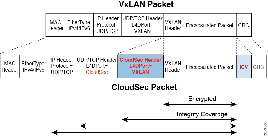
In order to provide a fully integrated, simple, and cost-effective solution that addresses both, data security and integrity, starting with Release 2.0(1), Multi-Site provides a CloudSec Encryption feature that allows for complete source-to-destination packet encryption between Multi-Site fabrics.
The following figure shows packet diagram before and after CloudSec encapsulation, followed by descriptions of the encryption and decryption processes:
Packet Encryption
The following is a high level overview of how CloudSec handles outgoing traffic packets:
-
The iVXLAN packets are filtered using outer IP header destination address field and Layer 4 destination port information and filtered packets are marked for encryption.
-
The offset to use for encryption is calculated according to the fields of the packet. For example, the offset may vary based on whether there is a 802.1q VLAN or if the packet is an IPv4 or IPv6 packet.
The offset is automatically determined and is not visible to the user.
-
The encryption keys are programmed in the hardware tables and are looked up from the table using the packet IP header.
Once the packet is marked for encryption, the encryption key is loaded, and the offset from the beginning of the packet where to start the encryption is known, the following additional steps are taken:
-
The UDP destination port number is copied from the UDP header into a CloudSec field for recovery when the packet is decrypted.
-
The UDP destination port number is overwritten to indicate that it is a CloudSec packet.
In releases prior to 3.7(1), the port is overwritten with a Cisco proprietary Layer-4 port number
9999.In release 3.7(1) or later where you can configure CloudSec to use the IANA-assigned port
8017, the destination port number used is either9999or8017depending on whether you enabled this option. -
The UDP length field is updated to reflect the additional bytes that are being added.
-
The CloudSec header is inserted directly after the UDP header.
-
The Integrity Check Value (ICV) is inserted at the end of the packet, between the payload and the CRC.
-
The ICV requires construction of a 128-bit initialization vector. For CloudSec, any use of the source MAC address for ICV purposes is replaced by a programmable value per SCI.
-
CRC is updated to reflect the change in the contents of the packet.
Packet Decryption
The way CloudSec handles incoming packets is symmetric to the outgoing packets algorithm described above:
-
If the received packet is a CloudSec packet, it is decrypted and the ICV is verified.
If ICV verification passed, the extra fields are removed, the UDP destination port number is moved from the CloudSec header to the UDP header, the CRC is updated, and the packet is forwarded to destination after decryption and CloudSec header removal. Otherwise the packet is dropped.
-
The decryption key is retrieved from the key store using the received CloudSec packet outer IP header source address field, CloudSec header SCI, and AN number fields.
-
If the packet is not a CloudSec packet, the packet is left unchanged.
CloudSec Encryption Key Allocation and Distribution
Initial Key Configuration
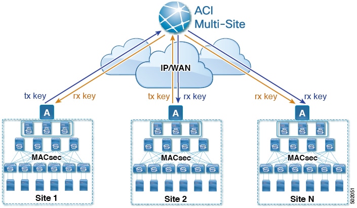
The following is a high level overview of the CloudSec encryption key initial allocation and distribution process illustrated by the figure above:
-
The upstream site’s Cisco APIC generates a local symmetric key intended to be used for data encryption of VXLAN packets transmitted from its site. The same key that is used by the upstream site for encryption is used for decryption of the packets on the downstream remote receiving sites.
Every site is an upstream site for the traffic it transmits to other sites. If multiple sites exist, each site generates its own site-to-site key and use that key for encryption before transmitting to the remote site.
-
The generated symmetric key is pushed to the Nexus Dashboard Orchestrator (NDO) by the upstream site’s Cisco APIC for distribution to downstream remote sites.
-
The NDO acts as a message broker and collects the generated symmetric key from the upstream site’s Cisco APIC, then distributes it to downstream remote sites' Cisco APICs.
The keys are encrypted using Key Encryption Key (KEK) and are distributed via a TLS-based channel.
-
Each downstream site’s Cisco APIC configures the received key as RX key on the local spine switches which are intended to receive the traffic from the upstream site that generated the key.
-
Each downstream site’s Cisco APIC also collects the deployment status of the RX Key from the local spine switches and then pushes it to the NDO.
-
The NDO relays the key deployment status from all downstream remote sites back to the upstream site’s Cisco APIC.
-
The upstream site’s Cisco APIC checks if the key deployment status received from all downstream remote sites is successful.
-
If the deployment status received from a downstream device is successful, the upstream site deploys the local symmetric key as its TX key on the spine switches to enable encryption of the VXLAN packets that are sent to the downstream site.
-
If the deployment status received from a downstream device is failed, a fault is raised on the Cisco APIC site where it failed and it is handled based on the "secure mode" setting configured on the NDO. In "must secure" mode the packets are dropped and in the "should secure" mode the packets are sent clear (unencrypted) to the destination site.
In current release, the mode is always set to "should secure" and cannot be changed.
-
Rekey Process
Each generated TX/RX key expires after a set amount of time, by default key expiry time is set to 15 minutes. When the initial set of TX/RX keys expires, a rekey process takes place.
The same general key allocation and distribution flow applies for the rekey process. The rekey process follows the "make before break" rule, in other words all the RX keys on the downstream sites are deployed before the new TX key is deployed on the upstream site. To achieve that, the upstream site will wait for the new RX key deployment status from the downstream sites before it configures the new TX key on the local upstream site’s devices.
If any downstream site reports a failure status in deploying the new RX key, the rekey process will be terminated and the old key will remain active. The downstream sites will also keep the old and the new RX keys after the new key deployment is finished for some duration to ensure that out of order packet deliveries with either key can be properly decrypted.
Special precautions must be taken in regards to rekey process during spine switch maintenance, see Rekey Process During Spine Switch Maintenance for details.
Rekey Process Failure
In case of any downstream site failing to deploy the new encryption key generated by the rekey process, the new key is discarded and the upstream device will continue to use the previous valid key as TX key. This approach keeps the upstream sites from having to maintain multiple TX keys per set of downstream sites. However, this approach may also result in the rekey process being delayed if the rekey deployment failures continue to occur with any one of the downstream sites. It is expected that the Multi-Site administrator will take action to fix the issue of the key deployment failure for the rekey to succeed.
Cisco APIC’s Role in Key Management
The Cisco APIC is responsible for key allocation (both, initial key and rekey distribution), collection of the key deployment status messages from the spine switches, and notification of the Nexus Dashboard Orchestrator about each key’s status for distribution to other sites.
Nexus Dashboard Orchestrator’s Role in Key Management
The Nexus Dashboard Orchestrator is responsible for collecting the TX keys (both, initial key and subsequent rekeys) from the upstream site and distributing it to all downstream sites for deployment as RX keys. The NDO also collects the RX key deployment status information from the downstream sites and notifies the upstream site in order for it to update the TX key on successful RX key deployment status.
Upstream Model
In contrast to other technologies, such as MPLS, that use downstream key allocation, CloudSec’s upstream model provides the following advantages:
-
The model is simple and operationally easier to deploy in the networks.
-
The model is preferred for Multi-Site use cases.
-
It provides advantages for multicast traffic as it can use the same key and CloudSec header for each copy of the replicated packet transmitted to multiple destination sites. In downstream model each copy would have to use a different security key for each site during encryption.
-
It provides easier troubleshooting in case of failures and better traceability of packets from the source to destination consistently for both, unicast and multicast replicated packets.
Configuring Cisco APIC for CloudSec Encryption
You must configure one or more Pre-Shared Keys (PSK) to be used by the Cisco APIC for generating the CloudSec encryption and decryption keys. The PSK are used as a random seed during the re-key process. If multiple PSK are configured, each re-key process will use the next PSK in order of their indexes; if no higher index PSK is available, a PSK with the lowest index will be used.
Because PSK is used as a seed for encryption key generation, configuring multiple PSK provides additional security by lowering the over-time vulnerability of the generated encryption keys.
If no pre-shared key is configured on the Cisco APIC, CloudSec will not be enabled for that site. In that case, turning on CloudSec setting in Multi-Site will raise a fault. If at any time you wish to refresh a previously added PSK with a new one, simply repeat the procedure as if you were adding a new key, but specify an existing index.
You can configure one or more pre-shared keys in one of three ways:
-
Using the Cisco APIC GUI, as described in Configuring for CloudSec Encryption Using GUI.
-
Using the Cisco APIC NX-OS Style CLI, as described in Configuring for CloudSec Encryption Using NX-OS Style CLI.
-
Using the Cisco APIC REST API, as described in Configuring for CloudSec Encryption Using REST API.
Configuring Cisco APIC for CloudSec Encryption Using GUI
This section describes how to configure one or more pre-shared keys (PSK) using the Cisco APIC GUI.
-
Log in to APIC.
-
Navigate to Tenants > infra > Policies > CloudSec Encryption
-
Specify the SA Key Expiry Time.
This option specifies how long each key is valid (in minutes). Each generated TX/RX key expires after the specified amount of time triggering a re-key process. The expiration time can be between 5 and 1440 minutes.
-
Click the + icon in the Pre-Shared Keys table.
-
Specify the Index of the pre-shared key you are adding and then the Pre-Shared Key itself.
The Index field specifies the order in which the pre-shared keys are used. After the last (highest index) key is used, the process will continue with the first (lowest index) key. Cisco APIC supports up to 256 pre-shared keys, so the PSK index value must be between 1 and 256.
Each Pre-Shared Key must be a hexadecimal string 64 characters long.
Configuring Cisco APIC for CloudSec Encryption Using NX-OS Style CLI
This section describes how to configure one or more pre-shared keys (PSK) using the Cisco APIC NX-OS Style CLI.
-
Log in to the Cisco APIC NX-OS style CLI.
-
Enter configuration mode.
apic1# configure apic1 (config)# -
Enter configuration mode for the default CloudSec profile.
apic1(config)# template cloudsec default apic1(config-cloudsec)# -
Specify the Pre-Shared Keys (PSK) expiration time.
This option specifies how long each key is valid (in minutes). Each generated TX/RX key expires after the specified amount of time triggering a re-key process. The expiration time can be between 5 and 1440 minutes.
apic1(config-cloudsec)# sakexpirytime__<duration>__ -
Specify one or more Pre-Shared Keys.
In the following command, specify the index of the PSK you’re configuring and the PSK string itself.
apic1(config-cloudsec)# pskindex__<psk-index>__
apic1(config-cloudsec)# pskstring__<psk-string>__
The <psk-index> parameter specifies the order in which the pre-shared keys are used. After the last (highest index) key is used, the process will continue with the first (lowest index) key. Cisco APIC supports up to 256 pre-shared keys, so the PSK index value must be between 1 and 256.
The <psk-string> parameter specifies the actual PSK, which must be a hexadecimal string 64 characters long.
-
(Optional) View the current PSK configuration.
You can view how many PSK are currently configured and their duration using the following command:
apic1(config-cloudsec)# show cloudsec summary
Configuring Cisco APIC for CloudSec Encryption Using REST API
This section describes how to configure one or more pre-shared keys (PSK) using the Cisco APIC REST API.
Configure PSK expiration time, index, and string.
In the following XML POST, replace:
-
The value of sakExpiryTime with the expiration time of each PSK.
This sakExpiryTime parameter specifies how long each key is valid (in minutes). Each generated TX/RX key expires after the specified amount of time triggering a re-key process. The expiration time can be between 5 and 1440 minutes.
-
The value of index with the index of the PSK you’re configuring.
The index parameter specifies the order in which the pre-shared keys are used. After the last (highest index) key is used, the process will continue with the first (lowest index) key. Cisco APIC supports up to 256 pre-shared keys, so the PSK index value must be between 1 and 256.
-
The value of pskString with the index of the PSK you’re configuring.
The pskString parameter specifies the actual PSK, which must be a hexadecimal string 64 characters long.
<fvTenant annotation="" descr="" dn="uni/tn-infra" name="infra" nameAlias="" ownerKey="" ownerTag="">
    <cloudsecIfPol descr="cloudsecifp" name="default" sakExpiryTime="__10__" stopRekey= "false" status="" >
        <cloudsecPreSharedKey index="__1__" pskString="__1234567812345678123456781234567812345678123456781234567812345678__" status=""/>
    </cloudsecIfPol>
</fvTenant>
Enabling CloudSec Encryption in Cisco Nexus Dashboard Orchestrator
Before you enable the CloudSec encryption between two or more sites, you must have completed the following tasks:
-
Installed and configured the Cisco APIC clusters in multiple sites, as described in Cisco APIC Installation, Upgrade, and Downgrade Guide
-
Installed and configured Cisco Nexus Dashboard Orchestrator, as described in Cisco Nexus Dashboard Orchestrator Installation and Upgrade Guide.
-
Added each Cisco APIC site to the Cisco Nexus Dashboard Orchestrator, as described in Cisco Multi-Site Configuration Guide.
The CloudSec encryption can be enabled or disabled for each site individually. However, the communications between two sites are encrypted only if the feature is enabled on both sites.
-
Log in to the Cisco Nexus Dashboard Orchestrator.
-
From the left navigation menu, select the Config > Site To Site Connectivity.
-
Click the Configure button in the top right of the main pane.
-
(Optional) In the General Settings page’s Control Plane Configuration tab, enable the IANA Reserved UDP Port option.
By default, CloudSec uses a proprietary UDP port. This option allows you to configure CloudSec to use the official IANA-reserved port 8017 for CloudSec encryption between sites.
The IANA-reserved port is supported for Cisco APIC sites running release 5.2(4) or later.
To change this setting, CloudSec must be disabled on all sites. If you want to enable IANA reserved port, but already have CloudSec encryption that is enabled for one or more of your sites, disable CloudSec for all sites, enable IANA Reserve UDP Port option, then re-enable CloudSec for the required sites.
-
From the left sidebar, select the site for which you want to change the CloudSec configuration.
-
In the right sidebar, toggle the CloudSec Encryption setting to enable or disable the CloudSec encryption feature for the site.
Verifying CloudSec Configuration on Switches
The following command allows you to see the current CloudSec configuration that was deployed to the spine switch after you enable CloudSec encryption from your Nexus Dashboard Orchestrator.
-
Log in to your spine switch.
-
Run the
show cloudsec sa interface allcommand to show CloudSec configuration.In the following output, ensure that for each
Interface:-
The
Operational Statusvalue showsUP. -
The
Controlvalue is the same across all interfaces in all CloudSec-enabled sites as it indicates the UDP port currently in use for CloudSec encryption.The following example shows the default Cisco-proprietary UDP port (
deprecatedUdpPort). If you configure CloudSec to use the IANA-assigned port 8017, the Control field will displayianaUdpPortinstead.
spine1# show cloudsec sa interface all ================================================================================ Interface: Eth1/49.49(0x1a030031) Physical Interface: Eth1/49(0x1a030000) *Operational Status: UP* Retry: Off *Control: deprecatedUdpPort* -------------------------------------------------------------------------------- Site-Id: 2 Peer: 200.200.204.0/24 Type: ext-routable-tep-pool Operational Status: UP Pod-Id: 1 -------------------------------------------------------------------------------- TX Key: ******************************** Assoc Num: 1 Sci: 0x10002 Cipher Suite: gcm-aes-xpn-256 Rekey Num: 6826 Oper Rekey Num: 6826 Hardware Index: 0 Operational Status: UP Control: NONE Last Updated: PST 2022-01-11 23:26:37.520-08:00 Retry: Off Uptime: 11 hours 30 mins 45 secs -------------------------------------------------------------------------------- Site-Id: 2 Peer: 200.200.202.1/32 Type: msite-unicast-tep Operational Status: UP -------------------------------------------------------------------------------- TX Key: ******************************** Assoc Num: 1 Sci: 0x10002 Cipher Suite: gcm-aes-xpn-256 Rekey Num: 6826 Oper Rekey Num: 6826 Hardware Index: 2 Operational Status: UP Control: NONE Last Updated: PST 2022-01-11 23:26:37.563-08:00 Retry: Off Uptime: 11 hours 30 mins 45 secs RX Key: ******************************** Assoc Num: 1 Sci: 0x20001 Cipher Suite: gcm-aes-xpn-256 Rekey Num: 6826 Oper Rekey Num: 6826 Hardware Index: 3 Operational Status: UP Control: NONE Last Updated: PST 2022-01-11 23:26:37.442-08:00 Retry: Off Uptime: 11 hours 30 mins 45 secs RX Key: ******************************** Assoc Num: 0 Sci: 0x20001 Cipher Suite: gcm-aes-xpn-256 Rekey Num: 6827 Oper Rekey Num: 6827 Hardware Index: 2 Operational Status: UP Control: NONE Last Updated: PST 2022-01-11 23:26:37.453-08:00 Retry: Off Uptime: 11 hours 30 mins 45 secs -------------------------------------------------------------------------------- Site-Id: 2 Peer: 200.200.201.1/32 Type: msite-multicast-tep Operational Status: UP -------------------------------------------------------------------------------- TX Key: ******************************** Assoc Num: 1 Sci: 0x10002 Cipher Suite: gcm-aes-xpn-256 Rekey Num: 6826 Oper Rekey Num: 6826 Hardware Index: 1 Operational Status: UP Control: NONE Last Updated: PST 2022-01-11 23:26:37.549-08:00 Retry: Off Uptime: 11 hours 30 mins 45 secs RX Key: ******************************** Assoc Num: 1 Sci: 0x20001 Cipher Suite: gcm-aes-xpn-256 Rekey Num: 6826 Oper Rekey Num: 6826 Hardware Index: 1 Operational Status: UP Control: NONE Last Updated: PST 2022-01-11 23:26:36.501-08:00 Retry: Off Uptime: 11 hours 30 mins 46 secs RX Key: ******************************** Assoc Num: 0 Sci: 0x20001 Cipher Suite: gcm-aes-xpn-256 Rekey Num: 6827 Oper Rekey Num: 6827 Hardware Index: 0 Operational Status: UP Control: NONE Last Updated: PST 2022-01-11 23:26:37.495-08:00 Retry: Off Uptime: 11 hours 30 mins 45 secs ================================================================================ Interface: Eth1/50.50(0x1a031032) Physical Interface: Eth1/50(0x1a031000) *Operational Status: UP* Retry: Off *Control: deprecatedUdpPort* -------------------------------------------------------------------------------- Site-Id: 2 Peer: 200.200.204.0/24 Type: ext-routable-tep-pool Operational Status: UP Pod-Id: 1 -------------------------------------------------------------------------------- TX Key: ******************************** Assoc Num: 1 Sci: 0x10002 Cipher Suite: gcm-aes-xpn-256 Rekey Num: 6826 Oper Rekey Num: 6826 Hardware Index: 1 Operational Status: UP Control: NONE Last Updated: PST 2022-01-11 23:26:37.577-08:00 Retry: Off Uptime: 11 hours 30 mins 45 secs -------------------------------------------------------------------------------- Site-Id: 2 Peer: 200.200.201.1/32 Type: msite-multicast-tep Operational Status: UP -------------------------------------------------------------------------------- TX Key: ******************************** Assoc Num: 1 Sci: 0x10002 Cipher Suite: gcm-aes-xpn-256 Rekey Num: 6826 Oper Rekey Num: 6826 Hardware Index: 0 Operational Status: UP Control: NONE Last Updated: PST 2022-01-11 23:26:37.537-08:00 Retry: Off Uptime: 11 hours 30 mins 45 secs RX Key: ******************************** Assoc Num: 1 Sci: 0x20001 Cipher Suite: gcm-aes-xpn-256 Rekey Num: 6826 Oper Rekey Num: 6826 Hardware Index: 1 Operational Status: UP Control: NONE Last Updated: PST 2022-01-11 23:26:36.463-08:00 Retry: Off Uptime: 11 hours 30 mins 46 secs RX Key: ******************************** Assoc Num: 0 Sci: 0x20001 Cipher Suite: gcm-aes-xpn-256 Rekey Num: 6827 Oper Rekey Num: 6827 Hardware Index: 0 Operational Status: UP Control: NONE Last Updated: PST 2022-01-11 23:26:37.416-08:00 Retry: Off Uptime: 11 hours 30 mins 45 secs -------------------------------------------------------------------------------- Site-Id: 2 Peer: 200.200.202.1/32 Type: msite-unicast-tep Operational Status: UP -------------------------------------------------------------------------------- TX Key: ******************************** Assoc Num: 1 Sci: 0x10002 Cipher Suite: gcm-aes-xpn-256 Rekey Num: 6826 Oper Rekey Num: 6826 Hardware Index: 2 Operational Status: UP Control: NONE Last Updated: PST 2022-01-11 23:26:37.593-08:00 Retry: Off Uptime: 11 hours 30 mins 45 secs RX Key: ******************************** Assoc Num: 0 Sci: 0x20001 Cipher Suite: gcm-aes-xpn-256 Rekey Num: 6827 Oper Rekey Num: 6827 Hardware Index: 2 Operational Status: UP Control: NONE Last Updated: PST 2022-01-11 23:26:37.481-08:00 Retry: Off Uptime: 11 hours 30 mins 45 secs RX Key: ******************************** Assoc Num: 1 Sci: 0x20001 Cipher Suite: gcm-aes-xpn-256 Rekey Num: 6826 Oper Rekey Num: 6826 Hardware Index: 3 Operational Status: UP Control: NONE Last Updated: PST 2022-01-11 23:26:37.507-08:00 Retry: Off Uptime: 11 hours 30 mins 45 secs -
Rekey Process During Spine Switch Maintenance
The following is a summary of the CloudSec rekey process during typical maintenance scenarios for the spine switches where the feature is enabled:
-
Normal Decommissioning - CloudSec rekey process stops automatically whenever a CloudSec-enabled spine switch is decommissioned. Rekey process will not start again until the decommissioned node is commissioned back or the decommissioned node ID is removed from the Cisco APIC
-
Spine Switch Software Upgrade - CloudSec rekey process stops automatically if a spine switch is reloaded due to software upgrade. Rekey process will resume after the spine switch comes out of reload.
-
Maintenance (GIR mode) - CloudSec rekey process must be manually stopped using the instructions provided in Disabling and Re-Enabling Re-Key Process Using NX-OS Style CLI. Rekey can be enabled back only after the node is ready to forward traffic again.
-
Decommissioning and Removal from - CloudSec rekey process must be manually stopped using the instructions provided in Disabling and Re-Enabling Re-Key Process Using NX-OS Style CLI. Rekey can be enabled back only after the node is removed from Cisco APIC.
Disabling and Re-Enabling Re-Key Process Using NX-OS Style CLI
It is possible to manually stop and restart the re-key process. You may be required to manually control the re-key process in certain situations, such as switch decommissioning and maintenance. This section describes how to toggle the setting using Cisco APIC NX-OS Style CLI.
-
Log in to the Cisco APIC NX-OS style CLI.
-
Enter configuration mode.
apic1# configure apic1(config)# -
Enter configuration mode for the default CloudSec profile.
apic1(config)# template cloudsec default apic1(config-cloudsec)# -
Stop or restart the re-key process.
To stop the re-key process:
apic1(config-cloudsec)# stoprekey yesTo restart the re-key process:
apic1(config-cloudsec)# stoprekey no
Disabling and Re-Enabling Re-Key Process Using REST API
It is possible to manually stop and restart the re-key process. You may be required to manually control the re-key process in certain situations, such as switch decommissioning and maintenance. This section describes how to toggle the setting using Cisco APIC REST API.
-
You can disable the rekey process using the following XML message.
<fvTenant annotation="" descr="" dn="uni/tn-infra" name="infra" nameAlias="" ownerKey="" ownerTag=""> <cloudsecIfPol descr="cloudsecifp" name="default" sakExpiryTime="10" stopRekey= "__true__" status="" /> </fvTenant> -
You can enable the rekey process using the following XML message.
<fvTenant annotation="" descr="" dn="uni/tn-infra" name="infra" nameAlias="" ownerKey="" ownerTag="">
    <cloudsecIfPol descr="cloudsecifp" name="default" sakExpiryTime="10" stopRekey= "__false__" status="" />
</fvTenant>
First Published: 2024-03-01
Last Modified: 2024-03-01
Americas Headquarters
Cisco Systems, Inc.
170 West Tasman Drive
San Jose, CA 95134-1706
USA
https://www.cisco.com
Tel: 408 526-4000
800 553-NETS (6387)
Fax: 408 527-0883