
vzAny with PBR Overview
The following sections provide an overview, requirements and guidelines, and configuration steps for enabling vzAny contracts with Policy-Base Redirects (PBR) in your Multi-Site domain. For an overview of vzAny in general and basic vzAny use cases that do not include PBR, see the vzAny Contracts chapter instead.
Use Cases
Prior to release 4.2(3), the following basic vzAny use cases (without PBR) were supported with Multi-Site, all of which are described in the vzAny Contracts chapter:
-
Free communication between EPGs within the same VRF.
-
Many-to-one communication allowing all EPGs within the same VRF to consume a shared service from a single EPG that is in the same or different VRF.
Beginning with NDO release 4.2(3), the following additional use cases for vzAny with PBR are supported for ACI fabrics running APIC release 6.0(4) or later, which allow redirecting traffic to a logical firewall service connected in each site in one-arm mode:
-
Any intra-VRF communication (vzAny-to-vzAny) between two EPGs or External EPGs within the same VRF.
-
Many-to-one communication between all the EPGs in a VRF (vzAny) and a specific EPG that is part of the same VRF.
-
Many-to-one communication between all the EPGs in a VRF (vzAny) and a specific External EPG that is part of the same VRF.
General Workflow for Configuring vzAny with PBR
The following sections describe how to create and configure the individual building blocks (such as templates, EPGs, contracts) that are required for all of the vzAny with PBR use cases followed by user-case-specific sections that provide the workflows necessary to put the individual building blocks together for the specific use case you want to configure.
When configuring any of the vzAny with PBR use cases, you will go through the following workflow which includes the new Service Device templates introduced in release 4.2(3) and used to define service graph configurations:
-
Create a Service Device template and associate it to a specific tenant and to all the sites where the configuration is required, which includes:
-
(Optional) Referencing an IP SLA policy.
The IP SLA policy must be already defined in a Tenant Policy template associated to the same tenant.
-
Creating one or more service node devices in the Service Device template.
Note that when you create a service device configuration, you will need to provide a bridge domain which must already exist in one of the Application templates. The exact BD requirements are listed in the following vzAny with PBR Guidelines and Limitations section.
-
Providing site-level configurations for the service node device defined in the Service Device template and deploying it.

Beginning with release 4.2(3) and the introduction of Service Device templates, there’s no Service Graph object that must be explicitly created in Nexus Dashboard Orchestrator for PBR use cases. NDO implicitly creates the service graph and deploys it in the site’s APIC.
-
-
Complete the configuration for the specific tenant associated to the Service Device template that you just created, which includes:
-
Creating a Tenant Application template and assigning it to all sites where the configuration is required.
-
Configuring vzAny VRF settings required to enable PBR and a contract.
-
Configuring the consumer and provider EPGs.
While the service BD must be stretched across sites, the BDs you use for the EPGs can be stretched or site-local.
-
-
Associate the service device you created in Step 1 with the vzAny contract you created in Step 2.
Please refer ACI Contract Guide and ACI PBR White Paper to understand Cisco ACI contract and PBR terminologies.
Traffic Flow: Intra-VRF vzAny-to-vzAny
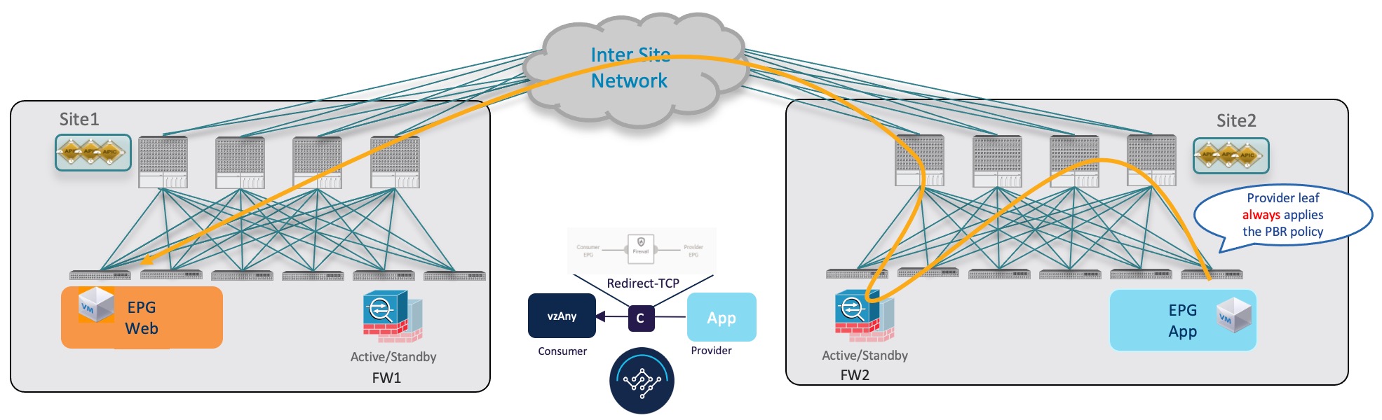
This section summarizes the traffic flow between two EPGs that are part of the logical vzAny construct for a given VRF in different sites. In this use case, vzAny is both the provider and the consumer of a PBR contract.
In this case, the traffic flow in both directions is redirected through both firewalls in order to avoid asymmetric traffic flows due to independent FW nodes deployed in the two sites.
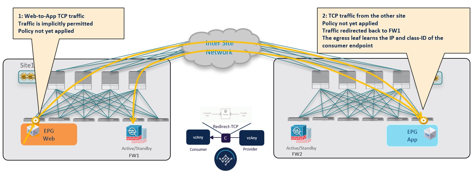
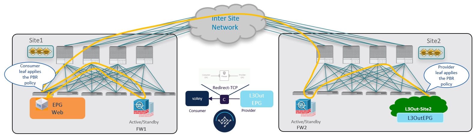
Initial Consumer-to-Provider Traffic Flow and Conversational Learning
The design principle for redirecting the traffic to the FW service nodes in both the local site and the remote site is that the PBR policy should always be applied on the ingress leaf switch for both directions of the traffic flow. For this to happen, the ingress leaf switch must be aware of the destination’s endpoint policy information (Class-ID). The figure below shows an example where communication is initiated from the consumer endpoint, and the ingress (consumer) leaf switch does not yet have the Class-ID information for the destination (provider) endpoint. So the traffic is simply forwarded toward the destination connected to the remote site. This release implements a new logic to support this use case, so that the provider leaf switch that receives the traffic can understand that the flow originated in Site 1 but it has not been sent through the firewall service node connected in that site. As a result, after learning the consumer endpoint information (Class-ID), the provider leaf in Site 2 bounces back the traffic toward the firewall in Site 1.
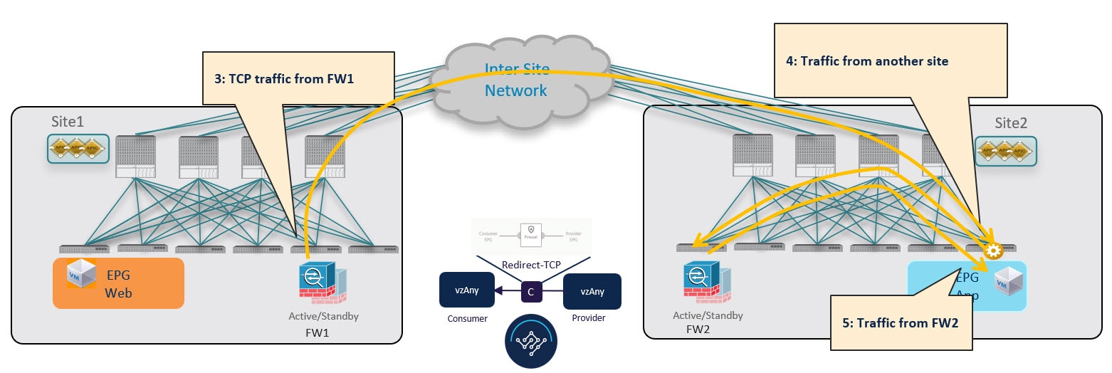
The firewall in Site 1 applies the security policy, then the traffic is forwarded again to the destination leaf switch in Site 2. This leaf is now able to understand that, while the traffic is still coming from Site 1, it now has been sent through the firewall deployed in that site. As a result, the destination leaf switch forwards the packet to its local firewall device for inspection and after that it is delivered to the destination endpoint as shown in the following figure.
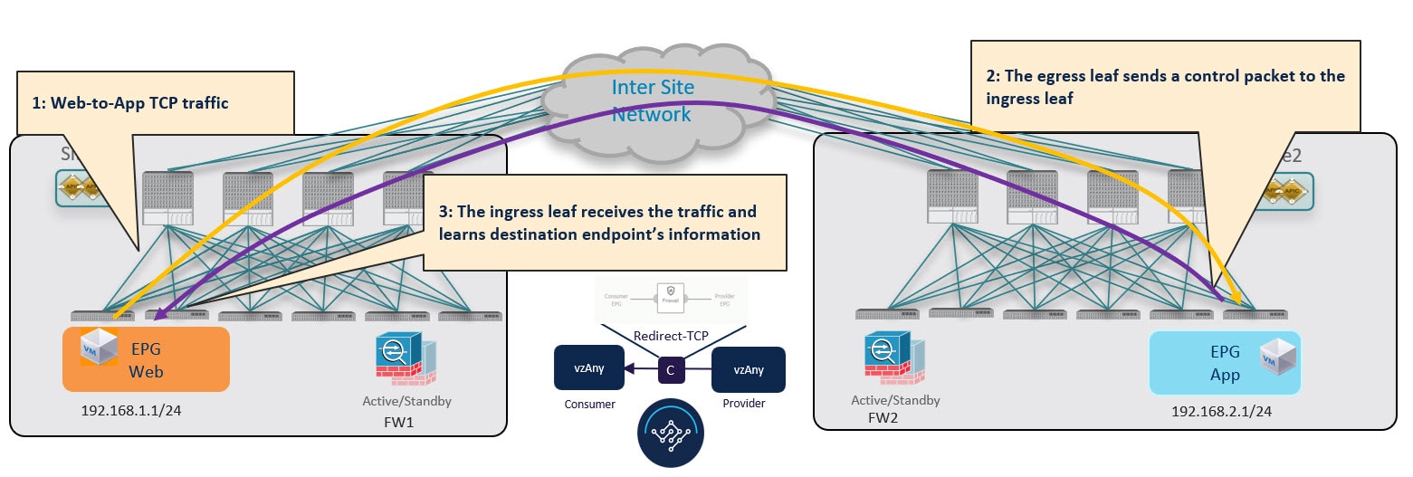
In order to avoid the suboptimal bounce of traffic shown in !!!Dita2Adoc_MissingReference:!!!, the provider leaf switch generates a special control packet and sends it to the consumer leaf switch in Site 1, so that the consumer leaf can learn the provider endpoint’s Class-ID information.
The same behavior described above for the consumer-to-provider traffic direction applies if the initial flow is established in the provider-to-consumer direction instead.
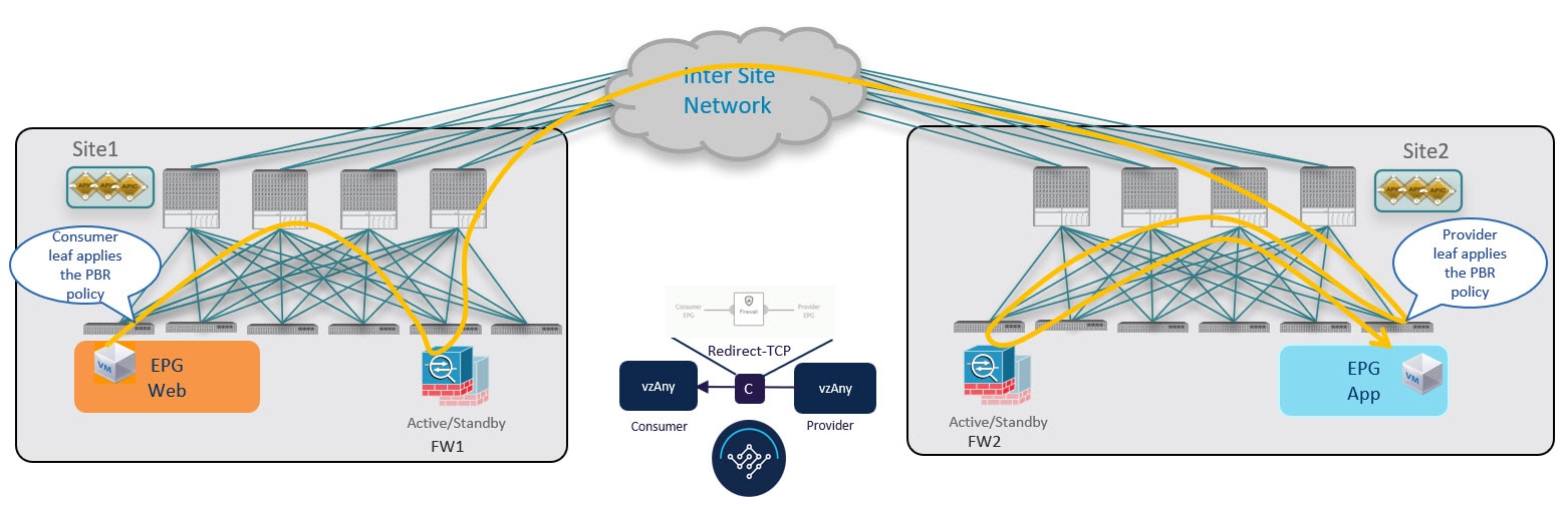
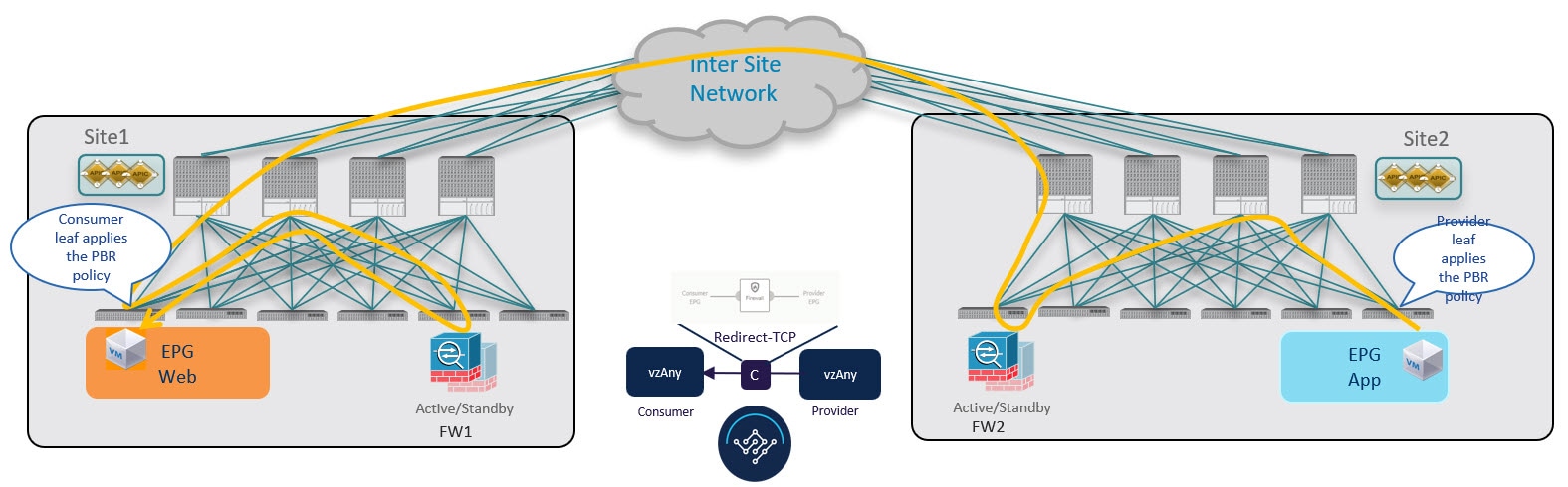
Consumer-to-Provider Traffic Flow (at Steady State)
After the consumer leaf switch has learned the provider endpoint information from the conversational learning stage described above, it can apply policy and redirect traffic to its local firewall for all future traffic:
Provider-to-Consumer Traffic Flow (at Steady State)
After the provider leaf switch has learned the consumer endpoint information either from the direct packet shown in !!!Dita2Adoc_MissingReference:!!! or based on conversational learning, it can apply policy and redirect traffic to its local firewall for all future traffic:
Traffic Flow: Intra-VRF vzAny-to-EPG
This section summarizes the traffic flow between a consumer EPG that is part of the logical vzAny construct for a given VRF and a provider EPG that is part of the same VRF. In this use case, vzAny is the consumer of the PBR contract, whereas a specific EPG is the provider.
Unlike the vzAny-to-vzAny and vzAny-to-L3Out use cases where traffic always flows through the firewall devices in both sites, vzAny-to-EPG always uses only the device in the provider’s site.
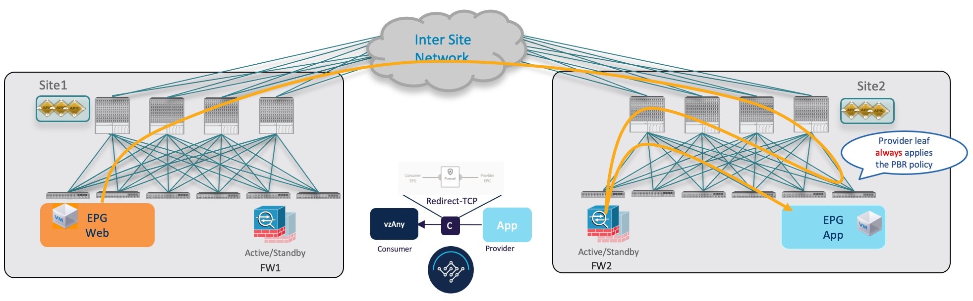
Consumer-to-Provider Traffic Flow
For the vzAny-to-EPG use case, policy is applied on the provider leaf switch only regardless of the traffic direction. So for consumer-to-provider traffic, the consumer EPG sends traffic directly to the provider EPG’s leaf switch, which learns the consumer endpoint information (Class-ID) and redirects the traffic to its local firewall for inspection:
Provider-to-Consumer Traffic Flow (Initial Traffic and Conversational Learning)
If the communication is initiated by the provider endpoint before the provider leaf switch can learn the consumer endpoint information (Class-ID), it cannot apply the policy to redirect traffic to its local firewall, so the traffic is sent across sites to the consumer leaf switch. Because the policy was not applied (indicated by a control bit in the packet), the consumer leaf switch redirects the traffic back to the provider site’s firewall for inspection, which finally bounces the traffic back to the consumer endpoint.
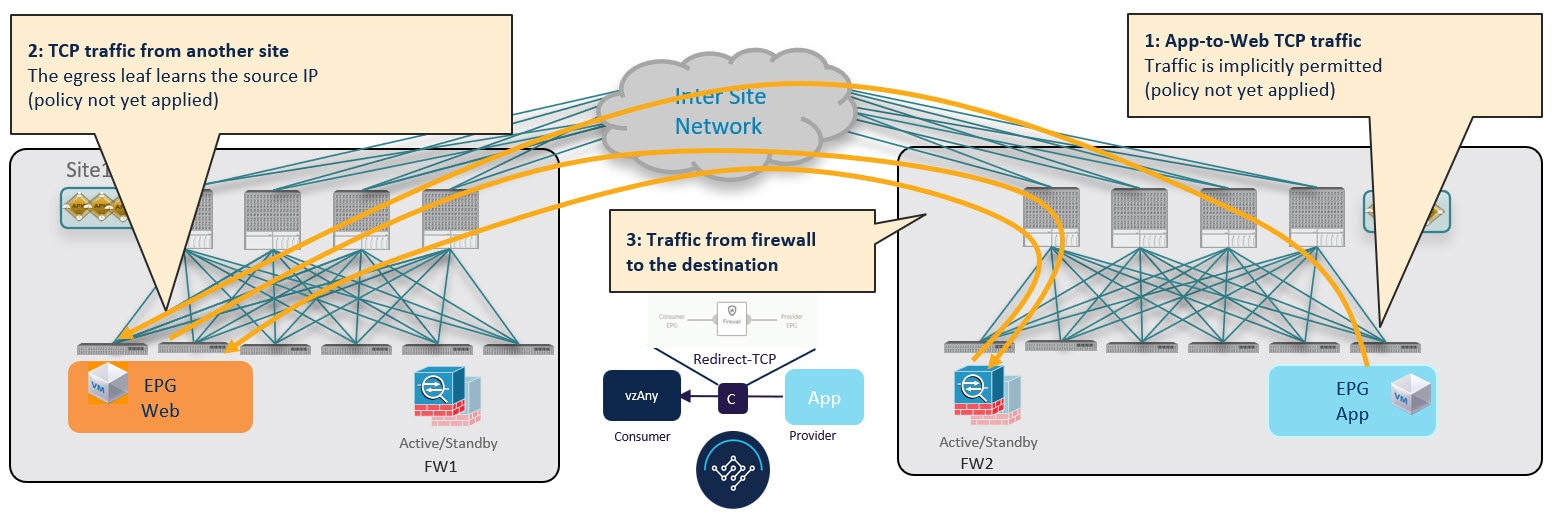
While this suboptimal traffic flow can continue indefinitely, the consumer EPG’s leaf switch also sends a separate control packet to the provider leaf switch with consumer endpoint information in order to optimizes future traffic and prevent it from bouncing between both sites:
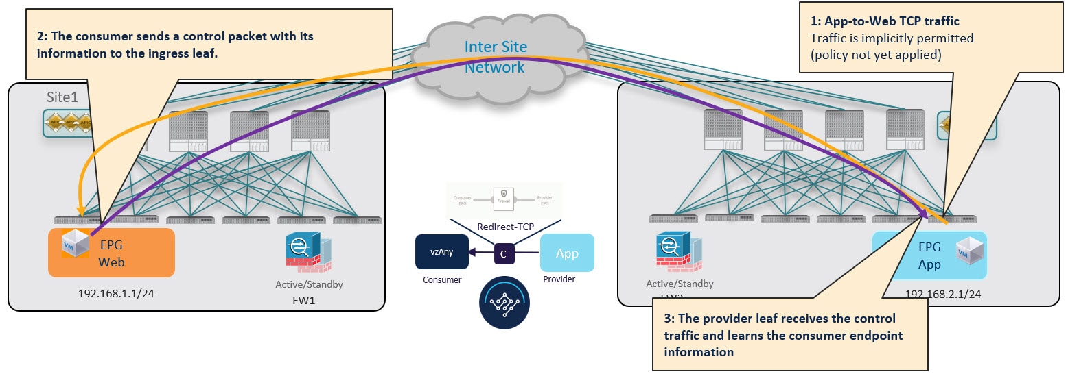
Provider-to-Consumer Traffic Flow (at Steady State)
After the provider leaf switch has learned the consumer endpoint information either from the direct packet originated from the consumer endpoint shown in !!!Dita2Adoc_MissingReference:!!! or based on conversational learning, it can apply policy and redirect traffic to its local firewall for all future traffic:
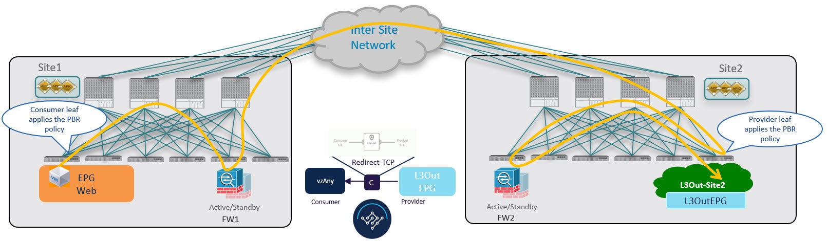
Traffic Flow: Intra-VRF vzAny-to-External-EPG (L3Out EPG)
This section summarizes the traffic flow between an EPG that is part of the logical vzAny construct for a given VRF and an external EPG (L3Out EPG) that is part of the same VRF in another site. In this use case, vzAny is the consumer of a vzAny contract, while an External EPG associated to the L3Out is the provider.
In this use case, the traffic is always redirected through firewall devices in both sites.
Consumer-to-Provider Traffic Flow
The ingress leaf switch can always resolve the class ID of the destination external EPG and applies the PBR policy redirecting the traffic to the local FW, so no conversational learning is necessary for traffic in this direction. Because the traffic is received by the provider leaf switch after going through the firewall node in Site 1, it is not possible for the provider leaf switch to learn the consumer endpoint information (Class-ID) from this data-plane communication.
Provider-to-Consumer Traffic Flow (Initial Traffic and Conversational Learning)
Before the provider leaf switch learns the consumer endpoint information, it cannot apply the policy to redirect traffic to its local firewall, so the traffic is sent across sites to the consumer leaf switch. Because the policy was not applied (indicated by a control bit in the packet), the consumer leaf switch redirects the traffic back to the provider site’s firewall for inspection, which finally forwards the traffic back to the consumer endpoint.
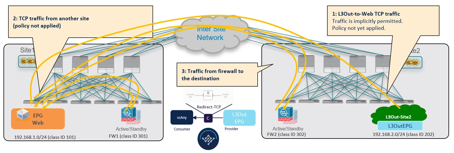
While this traffic flow can continue indefinitely, the consumer leaf switch also sends a separate control packet to the provider leaf switch with consumer endpoint information in order to optimizes future traffic and prevent it from bouncing between both sites:
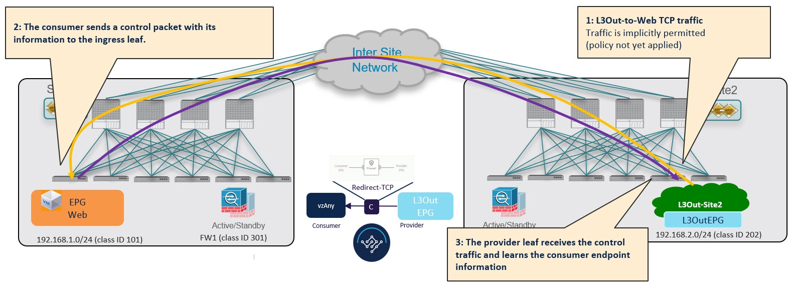
Provider-to-Consumer Traffic Flow (at Steady State)
After the provider leaf switch has learned the consumer endpoint information, it applies the PBR policy to redirect traffic to its local firewall device first, which then sends traffic across sites to the consumer leaf switch, which redirects traffic to the firewall device in its site and then finally to the consumer endpoint.
vzAny with PBR Guidelines and Limitations
The following guidelines and limitations apply when using vzAny with PBR in Multi-Site deployments:
The following sections apply to the vzAny with PBR use cases only. For information about basic vzAny concepts and use cases, see the vzAny Contracts chapter instead.
-
When configuring MultiSite Policy-Based Redirect (PBR) between Endpoint Groups (EPGs), the following features are not supported for specific IP endpoints or host prefixes (/32 for IPv4 and /128 for IPv6):
-
Static Route on a Bridge Domain (NH Reachability)
-
Microsoft Network Load Balancing
-
Anycast MAC
-
-
The ACI sites must be running Cisco APIC release 6.0(4) or later.
-
This release supports redirecting vzAny traffic to a single-node firewall or to a single-node load-balancer with a single interface attached to the service bridge domain. Single-Node firewall is supported in vzAny-to-vzAny and vzAny-to-L3Out, vzAny-to-EPG, and L3Out-to-L3Out use cases. Single-Node load-balancer is supported in vzAny-to-EPG use case.
This includes the following three use cases for one-arm mode firewall service graphs:
-
Any intra-VRF communication (vzAny-to-vzAny) across sites.
-
Many-to-one communication between all the EPGs in a VRF (vzAny) and a specific EPG that is part of the same VRF.
-
Many-to-one communication between all the EPGs in a VRF (vzAny) and a specific External EPG that is part of the same VRF.
In all of the above cases, conversational endpoint learning is enabled only when vzAny with PBR is configured and is used when IP prefixes under the EPG are not configured. A mix of EPGs with IP prefixes and EPGs without IP prefixes is also supported.
-
-
While you can use your existing Service Graph objects defined in Application templates for these use cases, we recommend using the new service chaining workflows introduced in release 4.2(3) and implicitly creating new service graphs by defining the policies in Service Device templates and associating them to contracts.
The steps described in the following sections use the new Service Device templates to enable the supported use cases but will call out the specific differences when applicable.
Configuration of Service Graph objects in Application templates will be deprecated in a future release.
-
The vzAny VRF must be stretched across the sites.
Note that the "Site-aware policy enforcement" and "L3 Multicast" options must be enabled for the vzAny VRF to enable the vzAny PBR use cases discussed in this chapter.
The following sections assume that you already have a VRF for which you have or will enable vzAny and which you will use for these use cases.
If you do not already have a VRF, you can create one in an Application template as you typically would. VRF configuration is described in detail in Configuring VRFs.
-
The service BD to which you want to attach the service device interface must be L2 stretched (BUM forwarding is instead optional and should be disabled).
If you do not already have a service BD, you can create one in an Application template as you typically would. BD configuration is described in detail in Configuring Bridge Domains.
-
The consumer, provider, and the service BDs must be configured in Hardware proxy-mode.
-
The vzAny PBR destination must be connected to a stretched service BD, not to an L3Out.
-
Only threshold down deny action and sip-dip-protocol hash is supported .
-
The PBR destination node must be in either the consumer or provider VRF instance. For example see Cisco Application Centric Infrastructure Policy-Based Redirect Service Graph Design White Paper.
The following is not supported for vzAny with PBR use case:
-
Specific Remote Leaf configurations.
-
Specific considerations apply for Multi-Site deployments leveraging Remote Leaf nodes. Intersite transit routing with PBR is not supported on vzAny PBR and L3Out-to-L3Out for communication between endpoints (consumer or provider) deployed on remote leaf nodes that belongs to different sites.
-
-
Each VRF is limited to utilizing only one device in a one-arm configuration for vzAny-to-vzAny, L3OutEPG-to-L3OutEPG, and vzAny-To-L3OutEPG Policy-Based Routing (PBR). This restriction is enforced due to special ACL in APIC.
-
We must use different firewall VLAN interfaces for redirection for vzAny-to-vzAny/L3OutEPG-to-L3OutEPG, and other use cases such as vzAny-to-EPG, EPG-to-EPG and EPG-to-L3OutEPG if they are in the same VRF.
-
When vzAny with PBR is applied to north-south communication for any of the newly supported use cases (vzAny-to-vzAny, vzAny-to-L3OutEPG, L3OutEPG-to-L3OutEPG), ingress traffic optimization needs to be enabled for stretched subnets.
-
Only one node service chain with L3 PBR destination is supported.
-
Contract Permit logging is not supported on the VRF that has Site-aware Policy Enforcement Mode is enabled, which is required for vzAny PBR and L3OutEPG-to-L3OutEPG PBR.
-
Pod-aware vzAny with PBR is not supported.
Create Service Device Template
-
Ensure that you have read and completed the requirements described in vzAny with PBR Guidelines and Limitations.
-
You must have created a stretched service bridge domain (BD) to use with the service nodes you will define in this section.
If you do not already have a BD, you can create one in an Application template as you typically would. BD configuration is described in detail in Configuring Bridge Domains.
The following steps describe how to create a Service Device template with a service node and its settings which you will use for the vzAny with PBR use cases.
-
Log in to the Nexus Dashboard Orchestrator GUI.
-
From the left navigation pane, select Configure > Tenant Templates.
-
(Optional) Create a Tenant Policies template and an IP SLA monitoring policy.
We recommend that you configure an IP SLA policy for traffic redirection as it simplifies the configuration of the PBR policy described in Step 7 below. If you have an IP SLA policy already defined, you can skip this step, otherwise:
-
Choose the Tenant Policies tab.
-
On the Tenant Policies page, click Create Tenant Policy Template.
-
In the Tenant Policies page’s right properties sidebar, provide the Name for the template and Select a Tenant.
-
In the Template Properties page, choose Actions > Add/Remove Sites and associate the template with both sites.
-
In the main pane, choose Create Object > IP SLA Monitoring Policy.
-
Provide the Name for the policy, and define its settings.
-
Click Save to save the template.
-
Click Deploy Template to deploy it.
-
-
Create a Service Device template and associate it with a tenant and with the sites.
-
From Configure > Tenant Templates, choose the Service Device tab.
-
Click Create Service Device Template.
-
In the template properties sidebar that opens, provide the Name for the template and Select a Tenant.
-
In the Template Properties page, choose Actions > Add/Remove Sites and associate the template with both sites.
-
Click Save to save the template.
-
-
Create and configure the device cluster.
-
In the Template Properties page (template-level configuration), choose Create Object > Service Device Cluster.
The device cluster defines the service to which you want to redirect traffic. This release supports redirection to a firewall service node that can be deployed with three different redundancy models: active/standby, active/active, or a cluster of multiple independent nodes. The provisioning for those different options is covered in Step 7 below. Note that you can choose the firewall deployment model at the site level and different options can be deployed across different fabrics that are part of the same Multi-Site domain.
-
In the <cluster-name> sidebar, provide the Name for the cluster.
The Device Location and Device Mode are pre-populated based on the currently supported use case. Device Location should be pre-configured as
ACI On-Premand Device Mode asL3. -
For Device Type, choose
Firewall.This release supports only firewall devices for the vzAny with PBR use cases.
-
For Device Mode, choose
L3. -
For Connectivity Mode, choose
One Arm.This release supports only one-arm device for the vzAny with PBR use cases.
When changing the device connectivity mode between one arm, two arm and advanced mode, the name of the device interface might change in the process. A warning message will alert the user, and any attempt to modify the interface will be restricted if the interface is currently in use by a contract. If the user wishes to preserve the previously used interface name and avoid disrupting the deployed configuration, they may choose to override the name change during the modification process.
Validations are conducted only for one-arm and two-arm modes. In Advanced mode, no validations are performed, and it is assumed that the user is an expert when choosing this mode.
-
Provide the Interface Name.
-
For the Interface Type, choose
BD.For vzAny with PBR use cases, this release supports attaching the service device to a bridge domain only.
-
Click Select BD > to choose the service bridge domain to which you want to attach this device.
This is the stretched service BD you created as part of the vzAny with PBR Guidelines and Limitations, for example
FW-external. -
For the Redirect option, choose
Yes.You must choose to enable redirect for the PBR use case. After choosing
Yes, the IP SLA Monitoring Policy option becomes available. -
(Optional) Click Select IP SLA Monitoring Policy and choose the IP SLA policy you have created in a previous step.
-
(Optional) In the Advanced Settings area, choose Enable if you want to provide additional settings for the service cluster.
You can configure the following advanced settings:
-
QoS Policy - allows you assign a specific QoS level within the ACI fabrics for the redirected traffic.
-
Preferred Group - specifies whether or not this service device interface is part of the preferred group.
Leave this option disabled when configuring a vzAny use case.
-
Load Balancing Hashing - allows you to specify the hashing algorithm for PBR load balancing.
You must keep the default value for the vzAny-to-vzAny, vzAny-to-ExtEPG, and ExtEPG-to-ExtEPG use cases as they support only the default configuration. You can change the load balancing hashing for other use cases: EPG-to-EPG, ExtEPG-to-EPG and vzAny-to-EPG.
For additional information, see ACI Policy-Based Redirect Service Graph Design.
-
Pod Aware Redirection - can be configured in Multi-Pod configuration if you want to specify the preferred PBR node. When you enable Pod-aware redirection, you can specify the Pod ID and redirection is programmed only in the leaf switches located in the specified Pod.
-
Rewrite Source MAC - updates the source MAC address if the PBR node uses "source MAC based forwarding" instead of IP based forwarding.
For additional information, see ACI Policy-Based Redirect Service Graph Design.
-
Advanced Tracking Options - allows you to configure a number of advanced settings for the service node tracking. For additional information, see Policy-Based Redirect and Threshold Settings for Tracking Service Nodes
-
-
Click Ok to save.
Note that after you create the Service Device Cluster, it is highlighted in red in the Template Properties (template-level configuration) page. At this point, you have defined redirection to a firewall service, but you must still provide the firewall information and the redirect policy you want to use at the site-local level.
-
-
Provide site-local configuration for the Service Device Cluster you created in the previous step.
-
In the Service Device Template screen, choose the <site-name> tab.
-
At the site level, choose the Service Device Cluster you created.
-
In the properties sidebar, choose the Domain Type.
You can choose whether the firewall device in this site is
PhysicalorVMM(virtual and hosted by a hypervisor that is part of a VMM domain). -
Click Select Domain to choose the domain to which this firewall device belongs.
You can choose either a physical or a virtual domain.
-
If you choose a physical domain, provide the following information:
-
VLAN - you must provide the VLAN ID used for traffic between the fabric and the firewall device.
-
Fabric to Device Connectivity - provide the switch node and interface information for the fabric’s connectivity to the firewall device.
-
-
If you choose a VMM domain, provide the additional options:
-
Trunking Port - used to enable tagged traffic for the L4-L7 VM.
By default, the ACI service graph configuration creates access-mode port groups and attaches them to the vNIC of the L4-L7 VM automatically.
-
Promiscuous Mode - required if the L4-L7 virtual appliance must receive traffic destined to a MAC address that is not the vNIC MAC owned by the VM.
-
VLAN - optional configuration for VMM domains and will be allocated from the dynamic VLAN pool associated with the domain if not specified.
-
Enhanced LAG Option - if you are using enhanced LACP for the port channel between the hypervisor and the fabric.
-
VM Name - choose the firewall’s VM from the list of all VMs available in this VMM domain and the interface (VNIC) used for the firewall traffic.
Depending on the kind of device cluster you are deploying, click +Add VM information to provide additional cluster nodes.
-
-
-
-
Provide the FW device information and PBR destination IP addresses.
As previously mentioned, this release supports 3 deployment options for high-availability FW clusters: active/standby clusters, active/active clusters, and independent active nodes. In all three deployment options, the use of an IP SLA policy (mentioned in Step 3) allows to specify only the IP address of the firewall nodes, and the corresponding MAC address will be automatically discovered.
You can deploy different designs in different sites.
-
Active/standby clusters are identified by a single MAC/IP pair.
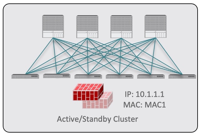 Figure 14.
In this case, you need to provide a single PBR destination IP address identifying the active firewall node and also include information about every node in the cluster.
For example, for a 2-nodes active/standby cluster, you would provide the following:-
For a virtual firewall cluster, the VMs representing the active and standby firewall nodes and the IP address of the active firewall as PBR destination.
-
For a physical firewall cluster, the interfaces used to connect the active and standby firewall nodes to the leaf switches of the fabric (vPC interfaces in the specific example below) and the IP address of the active firewall as PBR destination.
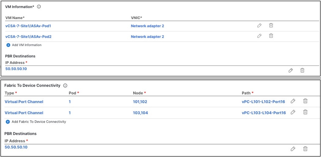 Figure 15.
-
-
Active/active clusters are also identified by a single MAC/IP pair.
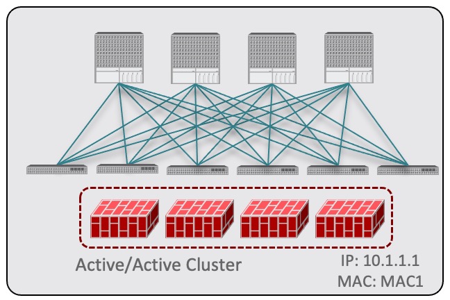 Figure 16.
For Cisco Firewalls (ASA or FTD models), the Active/Active cluster is only supported for physical form factors, and all the cluster nodes own the same MAC/IP address and must be connected to the same vPC logical connection deployed on a pair of ACI leaf switches. As a result, the figure below shows how a single vPC interface and a single IP address should be configured on NDO, where the MAC address is dynamically discovered when using an IP SLA policy mentioned for the previous use case.
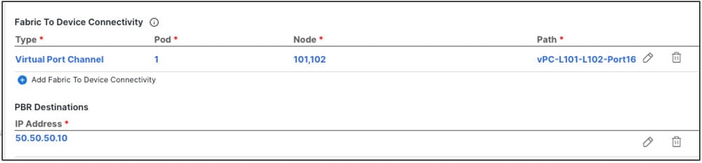 Figure 17.
 -
For independent active nodes configuration, each active node is identified by a unique MAC/IP addresses pair.
Note that symmetric PBR ensures that the traffic is handled by the same active node in both directions.
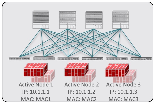 Figure 18.
In this case, you must provide individual IP addresses for each active node as well as each node’s information in your NDO configuration.
For example, for a deployment of 3 independent firewall nodes, you would provide the following:-
For a virtual firewall form factor, the VMs representing the 3 firewall nodes and their unique IP addresses as PBR destinations.
-
For a physical firewall form factor, the interfaces used to connect each firewall node to the leaf switches of the fabric (vPC interfaces in the specific example below) and the unique IP addresses of each firewall node as PBR destinations.
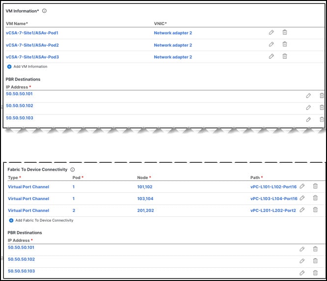 Figure 19.
-
Click Add Fabric To Device Connectivity (physical domain) or Add VM Information (VMM domain).
Depending on whether you selected physical or VMM domain in the previous step, you will specify information for either the firewall VM or the physical fabric connectivity to the firewall device.
For physical domains, provide the Pod, switch node, and the interface information.
For VMM domains, provide the VM name and vNIC information.
-
Click Add PBR Destination to provide the IP address of the interface on the firewall that is connected to the service bridge domain.
Depending on the kind of device cluster you are deploying, you may need to provide one or more PBR destination IP addresses:
This does not provision the IP address on the firewall’s interface, but simply configures redirection of traffic toward that IP address. The specific firewall configuration is not deployed from NDO, and you must provision it separately.
-
Click Ok to save the provided configuration.
-
Repeat this step for the other site with which you associated the template.
-
-
-
Save and deploy the template.
-
At the Service Device Template level, click Save to save the template configuration.
-
Choose the Template Properties tab and click Deploy Template to push the configuration to the sites.
-
(Optional) Verify that the configuration was created at the site level.
You can verify that the L4-L7 device is configured in the APIC by navigating to <tenant-name> > Services > L4-L7 > Devices > <cluster-name> in the APIC GUI. This shows the device cluster along with all the configuration you have provided in the previous steps.
To verify that the PBR policy is now configured on the APIC, navigate to <tenant-name> > Policies > Protocol > L4-L7 Policy-Based Redirect and you should see the <cluster-name>-one-arm redirect defined with the IP SLA monitoring policy you chose in Step 8i and the IP address you provided in Step 7d.
-
After you have deployed the service device configuration, create the application template and a contract with which you will associate the service chaining as described in Create Application Template.
Create Application Template
-
Ensure that you have read and completed the requirements described in vzAny with PBR Guidelines and Limitations.
-
You must have created a VRF for which you have or will enable vzAny and which you will use for these use cases.
If you do not already have a VRF, you can create one in an Application template as you typically would. VRF configuration is described in detail in Create Contract and Filters.
The following steps describe how to create tenant template(s) and the configuration objects which you will use for the vzAny with PBR use cases.
-
Log in to the Nexus Dashboard Orchestrator GUI.
-
From the left navigation pane, select Configure > Tenant Templates.
-
Choose the Applications tab.
-
Choose the Schema where you want to define your configuration.
If you have an existing Schema you want to update, simply click the Schema’s name in the main window pane. Otherwise, if you want to create a new Schema, click the Add Schema button and provide the schema information as you typically would.
-
Choose the Template where you want to define your configuration.
If you have an existing template you want to update, choose the template in the schema view.
While these steps describe how to create a single application template and stretch all objects across both sites, only the service BD (
BD FW-external) must be stretched. The EPG BDs can be configured as stretched or site-local; if you choose to configure site-local BDs for the EPGs, you will need to create additional application templates for those objects and assign them to the specific sites only.
To create a new template:
-
Click Create Template.
-
In the Select a Template Type screen, choose
ACI Multi-Cloud. -
Provide the Display Name for the template and Select a Tenant.
-
For the Deployment Mode, you can choose either
Multi-SiteorAutonomous.The vzAny with PBR use cases described in this chapter can be deployed for both Multi-Site and autonomous templates. If you choose to create an autonomous template, the redirection policy would apply only for intra-fabric traffic flows.
-
Click Continue to Template to save the information.
-
Choose ActionsAdd/Remove Sites and associate the template with the sites.
-
Repeat these substeps if you want to create additional templates for non-stretched objects.
-
-
Create a contract.
You will associate a service device previously defined in the Service Device template to this contract to enable the PBR functionality. The contract will then be used (consumed/provided) by vzAny and by EPG/ExtEPG depending on the specific use case to provision.
-
In the Template Properties view, choose Create Object > Contract to add a new contract.
-
Provide the name for the Contract.
For example,
vzAny-to-vzAny. -
From the Scope dropdown, choose
VRF.You must set the contract’s scope to VRF.
-
Click +Create Filter to add one or more contract filters.
For example, you can create a
Permit-IPcontract filter to redirect all traffic. -
Skip the Service Chaining/Service Graph configuration for now, you will associate a Service Device template to this contract in the next sections.
-
Define the other contract options as you typically would and click Ok to save.
-
-
Enable the required settings on the VRF.
-
Select the VRF you want to use for the vzAny with PBR use case.
You can use an existing VRF or create a new one as you typically would.
-
Enable vzAny and Add Contract that you created in the previous step.
The contract Type depends on the use case you want to configure:
-
For any intra-VRF communication (vzAny-to-vzAny) use case, assign the contract to the VRF twice - once as
consumerand again as aprovider. -
For many-to-one communication between all the EPGs in a VRF (vzAny) and specific EPG as part of same VRF, assign the contract as
consumerif you want the vzAny EPGs as consumer and specific EPG asprovider. -
Similarly, for many-to-one communication between all the EPGs in a VRF (vzAny) and a specific External EPG that is part of the same VRF, assign the contract as
consumerif you want the vzAny EPGs to consume a service provided by an L3Out External EPG.
-
-
Enable Site-aware Policy Enforcement Mode
You must enable the Site-aware Policy Enforcement Mode setting on the VRF to enable the new vzAny PBR use cases.
Enabling or disabling the Site-aware Policy Enforcement Mode option will cause a brief traffic disruption (including the already existing contracts between EPGs) because the zoning rules must be updated on the leaf switches. We recommend that you perform this operation during a maintenance window.
Enabling Site-aware Policy Enforcement Mode increases TCAM usage on the leaf switches for the existing contracts and contracting permit logging cannot be used in conjunction with this option.
-
Enable L3 Multicast.
The L3 Multicast option must be enabled for the vzAny VRF to enable the conversational learning functionality described earlier in this chapter.
-
Click Ok to save the changes.
-
-
Ensure that the service BD is associated with the same VRF as you used for the vzAny contract in the previous step.
-
Create application bridge domains, configured in hardware proxy mode.
Each application EPG that you will create in the next step requires a BD to be associated with it.
-
In the Template Properties view, choose Create ObjectBridge Domain.
-
Provide the name for the BD.
For example,
BD-App. -
From the Virtual Routing & Forwarding dropdown, ensure to select the VRF from the previous step.
-
Define the other BD options as you typically would.
For additional information about all available BD configurations, see Configuring Bridge Domains.
-
Click Ok to save the changes.
-
Repeat this step to create the second BD.
Following the illustration above, use
BD-Webfor the BD’s name.
-
-
Create the EPGs.
In this step, you will configure either two application EPGs or an application EPG and an External EPG depending on your specific use case.
-
Create an Application Profile by choosing +Create Object > Application Profile.
-
Choose +Create ObjectEPG and select the application profile you created.
-
In the properties pane, provide the Display Name for the EPG and choose the BD you created for this EPG.
For example,
EPG-App. For additional information about all available BD configurations, see Configuring Application Profiles and EPGs. -
Define the other EPG options as you typically would.
For additional information about all available BD configurations, see Configuring Bridge Domains.
-
Click Ok to save the changes.
-
Create a second EPG.
The type of the EPG and its contract configuration depend on the use case you want to configure:
-
Any intra-VRF communication (vzAny-to-vzAny).
This is the use case illustrated in Traffic Flow: Intra-VRF vzAny-to-vzAny, and you can simply create a second EPG in the same VRF. For example, create
EPG-Weband assign theBD-Webbridge domain to it. -
Many-to-one communication between all the EPGs in a VRF (vzAny) and a specific EPG that part of the same VRF
In this case, create a second EPG within the same VRF but explicitly assign the contract to it as
provider(the vzAny VRF contract for the specific EPG is assigned asconsumer). -
Many-to-one communication between all the EPGs in a VRF (vzAny) and a specific External EPG that is part of the same VRF
In this case, you must create an External EPG instead (+Create Object > External EPG), associate an L3Out with the external EPG, and then explicitly assign the contract to the External EPG as
provider.
-
-
-
Click Save Schema to save the defined configurations.
We recommend not deploying the template until the service chaining has been configured as described in the next section to avoid undesirable communication between endpoints without firewall redirection.
At this stage, you have effectively configured a basic use case for vzAny communication between two EPGs without adding service chaining with PBR:
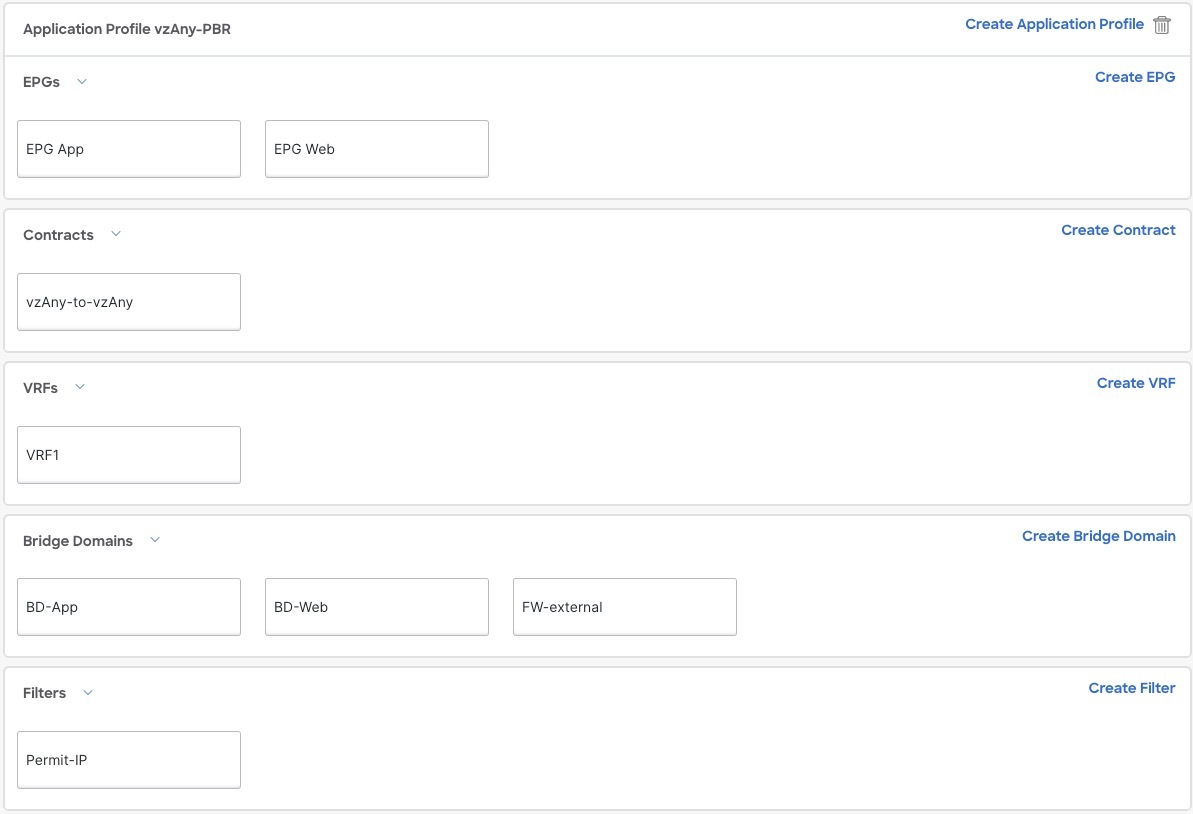 Figure 20.
The next section describes how to associate the service device you created in the previous section with the contract you created in the previous step.
After you have created the application template and the contract, proceed to associating the service device with the contract, as described in Add Service Chaining to Contract.
Add Service Chaining to Contract
-
You must have created and deployed the service device template containing the device configuration as described in Create Service Device Template.
-
You must have created (but not yet deployed) the application template containing the application bridge domains and EPGs as described in Create Application Template.
After you have created the application and the service device templates, you can add policy-based redirection by associating the contract with the service devices you created in a previous section.
-
Navigate back to the application template that you created in the previous section.
-
Select the contract you created in the previous section.
-
In the Service Chaining area, click +Service Chaining.
These steps assume that you have configured a brand new service device for this use case using the new Service Device template workflow introduced in release 4.2(3) as described in Create Service Device Template. If you already have a Service Graph defined in an application template, choose
Service Graphinstead and then select the existing service graph. However, keep in mind that the Service Graph option will be deprecated in a future release.
-
For Device Type, choose
Firewall.This release supports one-arm firewall service graphs only.
-
From the Device dropdown, choose the FW device cluster you created in the previous step.
-
Ensure that Consumer Connector Type Redirect is enabled.
-
Ensure that Provider Connector Type Redirect is enabled.
-
Click Add to continue.
-
Click Save to save the template.
-
Click Deploy Template to deploy it.
First Published: 2024-03-11
Last Modified: 2024-03-11
Americas Headquarters
Cisco Systems, Inc.
170 West Tasman Drive
San Jose, CA 95134-1706
USA
http://www.cisco.com
Tel: 408 526-4000
800 553-NETS (6387)
Fax: 408 527-0883