New and Changed Information
The following table provides an overview of the significant changes up to this current release. The table does not provide an exhaustive list of all changes or of the new features up to this release.
|
Release Version |
Feature |
Description |
|---|---|---|
|
NDFC release 12.1.2 |
-- |
Initial release of this use case document. |
|
NDFC release 12.1.3 |
Software image management of Cisco Catalyst 9000 Series switches. |
Introduces support for the following features:
|
Understanding Image Management
This document provides detailed information for the Image Management feature for Nexus Dashboard Fabric Controller release 12.x or later.
Image Management deploys Cisco software images to switches which allows network stability and feature consistency. The benefits of Image Management workflows include the following:
-
Comprehensive image management policies allow you to specify a version and patch level for a set of switches
-
Nexus Dashboard Fabric Controller (NDFC) validates compliance for the image policy associated with each switch
-
Image staging, validation, and in-service software upgrade (ISSU) operations are independent, allowing mass upgrades and downgrades

Note
Starting with Nexus Dashboard Fabric Controller release 12.1.3, NDFC provides the ability to perform staging and validation in a single step.
-
You can perform the following operations before the maintenance window:
-
Staging image files
This copies the image files to the bootflash.
-
Validate Network Operating System (NOS) and EPLD compatibility where possible
This checks if the image is complete, if the image is valid for the individual hardware, and if the upgrade can be non-disruptive.
-
Run pre-upgrade report
-
-
-
The ability to run reports pre/post-upgrade and compare the results
-
The ability to generate snapshots of the configuration pre/post-upgrade
-
The View Details column provides Live log status to monitor each operation
-
Allows you to make use of maintenance mode to minimize the impact of disruptive upgrades, especially for multi-reload upgrade situations
-
Allows you to perform multiple operations on the devices simultaneously. However, you cannot perform multiple operations on the same set of devices at the same time.
-
Upgrade groups allows bulk upgrades and downgrades. Upgrade groups have checks to avoid unnecessary downtime in redundant fabrics in the following cases:
-
All switches of a given role for a fabric will be in the same group
-
All route reflectors (RRs) in a fabric will be in the same group
-
All rendezvous points (RPs) in a fabric will be in the same group
-
Both Virtual Port Channel (vPC) peers will be in the same group
-
All In-Band Seed Devices will be in the same group
-
-
Provides visibility into previous and current upgrade details as well as high level summarization
-
Visibility into current NOS, EPLD and patch consistency at a switch, fabric, and group level
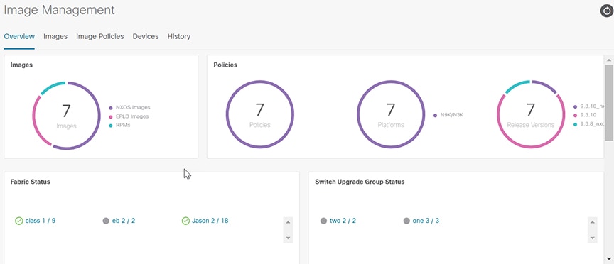
Starting with Nexus Dashboard Fabric Controller release 12.1.2, the Overview tab has changed and displays the images, policies, fabric status, and switch upgrade group status.
The Image Management UI has the following functional areas:
-
Overview: This displays the images, policies, fabric status, and switch upgrade group status.
-
The Images card displays the number of images and the type of packages or patches.
-
The Policies card displays the number of polices, platforms and release versions.
-
The Fabric Status card displays the number of devices in the fabric and if the devices are in or out of sync and displaying in either red or green.
-
The Switch Upgrade Group Status card displays the number of groups and device status.
-
Green: Devices that are in sync.
-
Red: Devices that are out of sync.
-
Gray: Devices that are not available (N/A). An example is when a device does not have a policy set.
-
-
-
Images: This displays the images. You can upload or delete images.
-
Image Polices: This displays the image policies. You can create, delete, or edit image policies.
-
Devices: This displays the devices. You can stage image, upgrade, validate, change mode, attach group, detach group, attach policy, or detach policy.
-
History: This displays the history of all the operations performed on the switches.
Terminology
This describes the terms that you must be familiar with:
|
Term |
Acronym |
Description |
|---|---|---|
|
Electronic Programmable Logic Device |
EPLD |
The EPLD image upgrades to enhance hardware functionality or to resolve known issues. |
|
In-Service Software Upgrade |
ISSU |
ISSU allows you to upgrade the software version of the release on a chassis device with no network downtime. |
|
Local Area Network |
LAN |
LAN consists of a series of computers linked together to form a network in a circumscribed location. |
|
Network Operating System |
NOS |
A specialized operating system designed for a network device such as a router, switch or firewall. Some examples include NX-OS for Nexus switches, IOS XE for Cisco Catalyst switches and so on. |
|
Rendezvous Points |
RP |
RP is a router that acts as the place where sources and receivers of multicast data can find each other. |
|
Route Reflector |
RR |
Route Reflector is a router that acts as a routing information exchange server for all other iBGP routers. |
|
Secure Copy |
SCP |
SCP is used by image management to transfer files between devices. |
Required Software Versions
For Cisco Nexus Dashboard services compatibility information, see the Cisco Data Center Networking Applications Compatibility Matrix.
Prerequisites
This section describes the prerequisites. This document assumes that the reader has a fundamental knowledge of Nexus Dashboard and Nexus Dashboard Fabric Controller.
-
SCP is used by Image Management. Both SCP and SNMP are always enabled by default and a minimum of 2 external service pool IPs are needed when you enable the Nexus Dashboard Fabric Controller.
-
Ensure that your user role is network-admin or device-upg-admin.
-
Ensure that there is a fabric, the fabric must have the "Deployment Enabled" flag set, and the switches are managed by the Nexus Dashboard Fabric Controller in this fabric.
-
Ensure you have LAN credential set.
Upgrade or Downgrade a Group of Switches
You have two upgrade methods and one downgrade method:
-
Disruptive Upgrade or Downgrade: During the upgrade or downgrade process the switches go down temporarily, which results in a disruption in your fabric traffic.
For more information, see Upgrading or Downgrading a Group of Switches (Disruptive).
-
Non-disruptive Upgrade: This allows the switches to run without disruption in your fabric traffic.
For more information, see Upgrading a Group of Switches (Non-disruptive).
-
Non-disruptive Downgrade: Not supported.
Upgrading or Downgrading a Group of Switches (Disruptive)
This section describes a disruptive method for upgrading or downgrading a group of switches.
If you are downgrading a group of switches, the process is identical to the process for upgrading a group of switches, except that the target image that you choose will be earlier than the currently installed image. The text for dialogs, fields, buttons, and other controls in the UI specify “upgrade” even though you are downgrading the software.
Downloading an Image from the Software Download Website
This section describes how to download an image from the software download website.
Procedure
|
Step 1 |
Go to the Software Download website. |
|
Step 2 |
Login with your credentials. You must login to download the software. |
|
Step 3 |
Navigate to Switches, choose a series and a switch. |
|
Step 4 |
Depending on the switch model, choose a software type:
|
|
Step 5 |
Choose the software file you want to download and click the download icon. |
Uploading the Image to Nexus Dashboard Fabric Controller
This section describes how to upload the image.
Procedure
|
Step 1 |
In the Image Management window, choose Image. |
|
Step 2 |
From the Actions drop-down list, select Upload. |
|
Step 3 |
In the Upload Image dialog box, either upload the file or import from SCP. Note that uploading an image to SCP or SFTP server from a non-Unix based device is not supported. |
|
Step 4 |
Click Verify. |
Creating the Image Policies
This section describes how to create the image policies.
Procedure
|
Step 1 |
In the Image Management window, choose Image Policies. |
|
Step 2 |
From the Actions drop-down list, select Create. |
|
Step 3 |
In the following Create Image Management Policy dialog box, enter the following information: 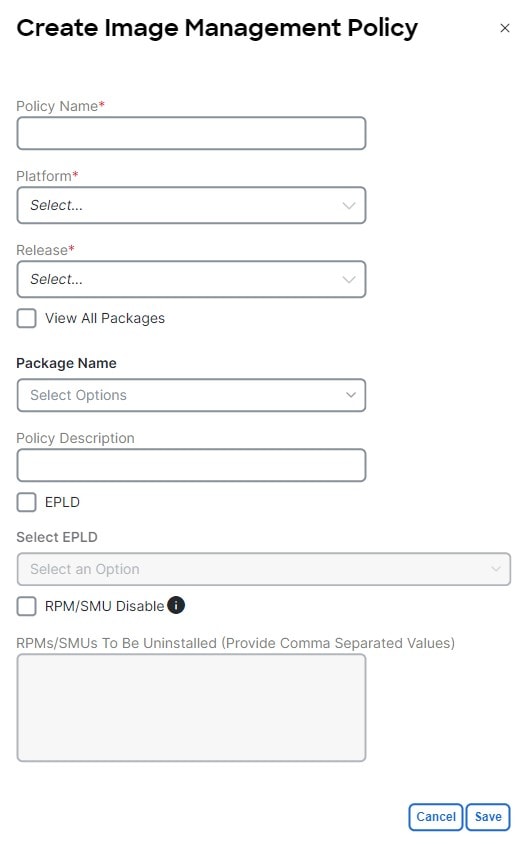 Depending on the switch type, not all fields in the Create Image Management Policy dialog box are available to all the devices. |
|
Step 4 |
Click Save. |
Creating and Attaching a Group to the Switches
This section describes how to create and attach a group to switches. Grouping allows you to track upgrades for a set of switches. You can create several groups and select a switch regardless of the group, role, or type of switch.
We recommend that you create upgrade groups based on the switch roles. For example, if a fabric has multiple switches with different roles, such as Leaf, Spine, Border, and more, creating groups based on different roles is recommended. This clearly separates roles and responsibilities during switch image management operations. Switches with different roles perform critical functionality and respond differently based on the control plane, data plane, and system-level convergence. For example, a user with the admin role can create multiple groups as follows:
-
Group-Leaf-Even for Leaf switches that have even numbers or VPC role of primary
-
Group-Leaf-Odd for Leaf switches that have odd numbers or VPC role of secondary
Typically, Spine and Border devices are limited to fabric, while the role of the Leaf is the most common one. Therefore, users with the admin role can upgrade individual Spines followed by Individual Borders, or create different groups for Spines and Borders. Users with the admin role can still leverage groups to divide the Leaf role switches and perform bulk actions.
Procedure
|
Step 1 |
In the Image Management window, choose Devices. |
|
Step 2 |
In the Devices window, place a checkmark in the checkbox for the devices you want to group. |
|
Step 3 |
From the Actions drop-down list, select Modify Groups. |
|
Step 4 |
In the Modify Groups dialog box, click the Attach Group radio button and choose Create Group or a group that was already created from the Group drop-down list. To create a group, enter a group name in the Modify Groups dialog box. |
|
Step 5 |
Click Save. |
Attaching a Policy to the Switches
This section describes how to attach a policy to the switches.
Procedure
|
Step 1 |
In the Image Management window, choose Devices. |
|
Step 2 |
In the Devices window, select the devices you want to attach a policy. |
|
Step 3 |
From the Actions drop-down list, select Modify Policy. |
|
Step 4 |
In the Modify Policy dialog box, click the Attach Policy radio button and choose the required policy from the Policy drop-down list. |
|
Step 5 |
(Optional) Check or uncheck the Stage & Validate check box, as required. This option deploys the image on to the switch and validates for compatibility with the existing software version on the switch. The check box is enabled by default. You can uncheck this field while attaching the policy and do a manual stage and validate, if required. For more information, see Copying the Image to the Switches and Validating the Switches (Optional). |
|
Step 6 |
Click Attach. The table in the Devices tab displays the status of the stage and validate operations. |
|
Step 7 |
(Optional) Click the link in the View Details column to view the install log for details about these operations. You can use the log to learn about errors, if any. The History tab also provides logs for all the configuration changes and details about the errors. On successful completion, the Image Staged and Validated columns will display a green icon for the respective devices.
|
What to do next
Copying the Image to the Switches
The section describes how to copy the image to the switches.
Procedure
|
Step 1 |
In the Image Management window, choose Devices. |
|
Step 2 |
In the Devices window, place a checkmark in the checkbox for the device you want. |
|
Step 3 |
From the Actions drop-down list, select Stage Image. |
|
Step 4 |
In the Stage Image window, ensure there is enough space. The Primary Supervisor (Available Space in Bytes) displays in red if there is not enough space. 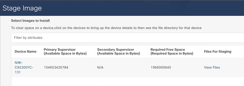 To make more space:
|
|
Step 5 |
Click Stage. |
Validating the Switches (Optional)
Before you begin
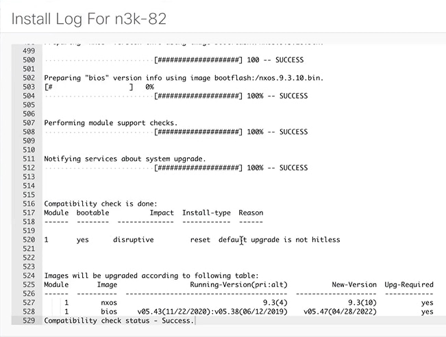
This section describes how to validate the switches to find out which switches can be upgraded by doing a compatibility check. This checks if the image is complete, if the image is valid for the individual hardware, and if the upgrade can be non-disruptive. The log files provide detailed information for each switch.
Procedure
|
Step 1 |
In the Image Management window, choose Devices. |
|
Step 2 |
In the Devices window, place a checkmark in the checkbox for the device you want to validate. |
|
Step 3 |
From the Actions drop-down list, select Validate. |
|
Step 4 |
In the Validate dialog box, place a checkmark in the checkbox if you want a non-disruptive upgrade. |
|
Step 5 |
Click Validate. |
|
Step 6 |
In the Image Management window, under the View Details column, click Validate to check on the log file for that switch.  |
|
Step 7 |
In the Image Management window, under the Validated column, you can see the validation progress until it completes.
|
Creating and Running the Pre-ISSU Report on the Switches (Optional)
This section describes how to create and run the pre-ISSU report on the switches (optional).
Procedure
|
Step 1 |
In the Image Management window, choose Devices. |
|
Step 2 |
In the Devices window, place a checkmark in the checkbox for the devices you want to run a report. |
|
Step 3 |
From the Actions drop-down list, select Run Reports. |
|
Step 4 |
In the Create Report dialog box, choose Pre ISSU radio button. |
Generating Pre-Upgrade Snapshots of the Switch Configuration (Optional)
This topic describes how to generate snapshots of the configuration of a switch. It is a best practice to generate snapshots of the switch configuration before entering and exiting the maintenance mode for performing an upgrade. You can use this to compare the configuration of the switch before it was moved into maintenance mode and after bringing back to normal mode.
Procedure
|
Step 1 |
In the Image Management window, choose Devices. |
|
Step 2 |
In the Devices window, place a checkmark in the checkbox for the required device. |
|
Step 3 |
From the Actions drop-down list, choose Generate Snapshot. |
|
Step 4 |
In the Generate Snapshot dialog box, click Pre-Upgrade-Snapshot. |
|
Step 5 |
Click Save. The system generates a pre-upgrade snapshot for the switch. |
|
Step 6 |
Click the link in the View Details column for the respective switch to view the snapshot generated for the switch. The History tab also provides logs for all the configuration changes and details about the errors. |
Changing to Maintenance Mode
This section describes how to change to maintenance mode.
Procedure
|
Step 1 |
In the Image Management window, choose Devices. |
|
Step 2 |
In the Devices window, place a checkmark in the checkbox for the device you want. |
|
Step 3 |
From the Actions drop-down list, select Change Mode. |
|
Step 4 |
In the Change Mode dialog box, choose Maintenance and click Save and Deploy Now. |
Upgrading or Downgrading Switches
This section describes how to upgrade or downgrade a switch or a group of switches.
Procedure
|
Step 1 |
In the Image Management window, choose Devices. |
||
|
Step 2 |
Do one of the following:
|
||
|
Step 3 |
From the Actions drop-down list, select Upgrade.
|
Changing to Normal Mode
This section describes how to change to normal mode.
Procedure
|
Step 1 |
In the Image Management window, choose Devices. |
||
|
Step 2 |
In the Devices window, place a checkmark in the checkbox for the device you want. |
||
|
Step 3 |
From the Actions drop-down list, select Change Mode. |
||
|
Step 4 |
In the Change Mode dialog box, choose Normal and click Save and Deploy Now. Repeat the following procedure for the next group:
|
Running the Post-ISSU Report on the Switches (Optional)
This section describes how to run the post-ISSU report on switches only if the mode was changed to normal mode.
Note |
For release 12.1.2, you must wait until the switch is fully operational before running the Post-ISSU. |
Procedure
|
Step 1 |
In the Image Management window, choose Devices. |
|
Step 2 |
In the Devices window, place a checkmark in the checkbox for the devices you want to run the post-ISSU. |
|
Step 3 |
From the Actions drop-down list, select Run Reports. |
|
Step 4 |
In the Create Report dialog box, choose Post ISSU radio button. |
|
Step 5 |
Perform the following to view the reports: |
Generating Post-Upgrade Snapshot of the Switch Configuration (Optional)
This topic describes how to generate snapshots of the configuration of a switch. It is a best practice to generate snapshots of the switch configuration before entering and exiting the maintenance mode for performing an upgrade. You can use this to compare the configuration of the switch before it was moved into maintenance mode and after bringing back to normal mode.
Procedure
|
Step 1 |
In the Image Management window, choose Devices. |
|
Step 2 |
In the Devices window, place a checkmark in the checkbox for the required device. |
|
Step 3 |
From the Actions drop-down list, choose Generate Snapshot. |
|
Step 4 |
In the Generate Snapshot dialog box, click Post-Upgrade-Snapshot. |
|
Step 5 |
Click Save. The system generates a post upgrade snapshot for the switch. |
|
Step 6 |
Click the link in the View Details column for the respective switch to view the snapshots and the pre and post snapshot comparison summary generated for the switch. The History tab also provides logs for all the configuration changes and details about the errors. |
Upgrading a Group of Switches (Non-disruptive)
This section describes a non-disruptive method for upgrading a group of switches.
Downloading an Image from the Software Download Website
This section describes how to download an image from the software download website.
Procedure
|
Step 1 |
Go to the Software Download website. |
|
Step 2 |
Login with your credentials. You must login to download the software. |
|
Step 3 |
Navigate to Switches, choose a series and a switch. |
|
Step 4 |
Choose a software type:
|
|
Step 5 |
Choose the software file you want to download and click the download icon. |
Uploading the Image to Nexus Dashboard Fabric Controller
This section describes how to upload the image.
Procedure
|
Step 1 |
In the Image Management window, choose Image. |
|
Step 2 |
From the Actions drop-down list, select Upload. |
|
Step 3 |
In the Upload Image dialog box, either upload the file or import from SCP. Note that uploading an image to SCP or SFTP server from a non-Unix based device is not supported. |
|
Step 4 |
Click Verify. |
Creating the Image Policies
This section describes how to create the image policies.
Procedure
|
Step 1 |
In the Image Management window, choose Image Policies. |
|
Step 2 |
From the Actions drop-down list, select Create. |
|
Step 3 |
In the Create Image Management Policy dialog box, enter the following information: Depending on the switch type, not all fields in the Create Image Management Policy dialog box are available to all the devices. |
|
Step 4 |
Click Save. |
Creating and Attaching a Group to the Switches
This section describes how to create and attach a group to switches. Grouping allows you to track upgrades for a set of switches. You can create several groups and select a switch regardless of the group, role, or type of switch.
We recommend that you create upgrade groups based on the switch roles. For example, if a fabric has multiple switches with different roles, such as Leaf, Spine, Border, and more, creating groups based on different roles is recommended. This clearly separates roles and responsibilities during switch image management operations. Switches with different roles perform critical functionality and respond differently based on the control plane, data plane, and system-level convergence. For example, a user with the admin role can create multiple groups as follows:
-
Group-Leaf-Even for Leaf switches that have even numbers or VPC role of primary
-
Group-Leaf-Odd for Leaf switches that have odd numbers or VPC role of secondary
Typically, Spine and Border devices are limited to fabric, while the role of the Leaf is the most common one. Therefore, users with the admin role can upgrade individual Spines followed by Individual Borders, or create different groups for Spines and Borders. Users with the admin role can still leverage groups to divide the Leaf role switches and perform bulk actions.
Procedure
|
Step 1 |
In the Image Management window, choose Devices. |
|
Step 2 |
In the Devices window, place a checkmark in the checkbox for the devices you want to group. |
|
Step 3 |
From the Actions drop-down list, select Modify Groups. |
|
Step 4 |
In the Modify Groups dialog box, click the Attach Group radio button and choose Create Group or a group that was already created from the Group drop-down list. To create a group, enter a group name in the Modify Groups dialog box. |
|
Step 5 |
Click Save. |
Attaching a Policy to the Switches
This section describes how to attach a policy to the switches.
Procedure
|
Step 1 |
In the Image Management window, choose Devices. |
|
Step 2 |
In the Devices window, select the devices you want to attach a policy. |
|
Step 3 |
From the Actions drop-down list, select Modify Policy. |
|
Step 4 |
In the Modify Policy dialog box, click the Attach Policy radio button and choose the required policy from the Policy drop-down list. |
|
Step 5 |
(Optional) Place a check mark in the Stage & Validate checkbox, if needed. This option deploys the image on to the switch and validates for compatibility with the existing software version on the switch. The check box is enabled by default. You can uncheck this field while attaching the policy and do a manual stage and validate, if required. For more information, see Copying the Image to the Switches and Validating the Switches (Optional). |
|
Step 6 |
Click Attach. The table in the Devices tab displays the status of the stage and validate operations. |
|
Step 7 |
(Optional) Click the link in the View Details column to view the install log for details about these operations. You can use the log to learn about errors, if any. The History tab also provides logs for all the configuration changes and details about the errors. On successful completion, the Image Staged and Validated columns will display a green icon for the respective devices.
|
|
Step 8 |
Click Save. |
Copying the Image to the Switches
The section describes how to copy the image to the switches.
Procedure
|
Step 1 |
In the Image Management window, choose Devices. |
|
Step 2 |
In the Devices window, place a checkmark in the checkbox for the device you want. |
|
Step 3 |
From the Actions drop-down list, select Stage Image. |
|
Step 4 |
In the Stage Image window, ensure there is enough space. The Primary Supervisor (Available Space in Bytes) displays in red if there is not enough space. To make more space:
|
|
Step 5 |
Click Stage. |
Validating the Switches (Optional)
This section describes how to validate the switches to find out which switches can be upgraded by doing a compatibility check. This checks if the image is complete, if the image is valid for the individual hardware, and if the upgrade can be non-disruptive. The log files provide detailed information for each switch.
Procedure
|
Step 1 |
In the Image Management window, choose Devices. |
|
Step 2 |
In the Devices window, place a checkmark in the checkbox for the device you want to validate. |
|
Step 3 |
From the Actions drop-down list, select Validate. |
|
Step 4 |
In the Validate dialog box, place a checkmark in the checkbox if you want a non-disruptive upgrade. |
|
Step 5 |
Click Validate. |
|
Step 6 |
In the Image Management window, under the View Details column, click Validate to check on the log file for that switch. |
|
Step 7 |
In the Image Management window, under the Validated column, you can see the validation progress until it completes.
|
Creating and Running the Pre-ISSU Report on the Switches (Optional)
This section describes how to create and run the pre-ISSU report on the switches (optional).
Procedure
|
Step 1 |
In the Image Management window, choose Devices. |
|
Step 2 |
In the Devices window, place a checkmark in the checkbox for the devices you want to run a report. |
|
Step 3 |
From the Actions drop-down list, select Run Reports. |
|
Step 4 |
In the Create Report dialog box, choose Pre ISSU radio button.
|
Generating Pre-Upgrade Snapshots of the Switch Configuration (Optional)
This topic describes how to generate snapshots of the configuration of a switch. It is a best practice to generate snapshots of the switch configuration before entering and exiting the maintenance mode for performing an upgrade. You can use this to compare the configuration of the switch before it was moved into maintenance mode and after bringing back to normal mode.
Procedure
|
Step 1 |
In the Image Management window, choose Devices. |
|
Step 2 |
In the Devices window, place a checkmark in the checkbox for the required device. |
|
Step 3 |
From the Actions drop-down list, choose Generate Snapshot. |
|
Step 4 |
In the Generate Snapshot dialog box, click Pre-Upgrade-Snapshot. |
|
Step 5 |
Click Save. The system generates a pre-upgrade snapshot for the switch. |
|
Step 6 |
Click the link in the View Details column for the respective switch to view the snapshot generated for the switch. The History tab also provides logs for all the configuration changes and details about the errors. |
Upgrading a Group of Switches
This section describes how to upgrade a group of switches.
Procedure
|
Step 1 |
In the Image Management window, choose Devices. |
||
|
Step 2 |
In the Devices window, filter on the Upgrade Groups, select all, and place a checkmark in the checkbox for all the devices you want. |
||
|
Step 3 |
From the Actions drop-down list, select Upgrade.
|
||
|
Step 4 |
After all the switches within the group are fully upgraded. Repeat this procedure for the next group. |
Running the Post-ISSU Report on the Switches (Optional)
This section describes how to run the post-ISSU report on switches (Optional).
Procedure
|
Step 1 |
In the Image Management window, choose Devices. |
|
Step 2 |
In the Devices window, place a checkmark in the checkbox for the devices you want to run the post-ISSU. |
|
Step 3 |
From the Actions drop-down list, select Run Reports. |
|
Step 4 |
In the Create Report dialog box, choose Post ISSU radio button.
|
Generating Post-Upgrade Snapshot of the Switch Configuration (Optional)
This topic describes how to generate snapshots of the configuration of a switch. It is a best practice to generate snapshots of the switch configuration before entering and exiting the maintenance mode for performing an upgrade. You can use this to compare the configuration of the switch before it was moved into maintenance mode and after bringing back to normal mode.
Procedure
|
Step 1 |
In the Image Management window, choose Devices. |
|
Step 2 |
In the Devices window, place a checkmark in the checkbox for the required device. |
|
Step 3 |
From the Actions drop-down list, choose Generate Snapshot. |
|
Step 4 |
In the Generate Snapshot dialog box, click Post-Upgrade-Snapshot. |
|
Step 5 |
Click Save. The system generates a post upgrade snapshot for the switch. |
|
Step 6 |
Click the link in the View Details column for the respective switch to view the snapshots and the pre and post snapshot comparison summary generated for the switch. The History tab also provides logs for all the configuration changes and details about the errors. |
Uninstalling Packages From a Switch
This section describes how to uninstall packages from a switch. You first need to take note of the patch names, detach the packages, and then uninstall them.
Procedure
|
Step 1 |
In the Nexus Dashboard Fabric Controller window, choose . |
||
|
Step 2 |
In the Switches window, place a checkmark in the checkbox for the device you want to uninstall packages from. |
||
|
Step 3 |
From the Actions drop-down list, select . |
||
|
Step 4 |
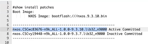
In the Switch Show Commands window, enter the following:
|
||
|
Step 5 |
In the Nexus Dashboard Fabric Controller window, choose . |
||
|
Step 6 |
In the Image Management window, choose Image Policies. |
||
|
Step 7 |
From the Actions drop-down list, select Create. |
||
|
Step 8 |
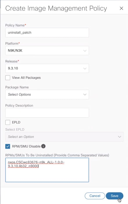
In the Created Image Management Policy dialog box, enter the following:
|
||
|
Step 9 |
In the Image Management window, choose Device. |
||
|
Step 10 |
In the Devices window, place a checkmark in the checkbox for the devices you want to modify the policy. |
||
|
Step 11 |
From the Actions drop-down list, select Modify Policy. |
||
|
Step 12 |
In the Modify Policy dialog box, enter the following:
|
||
|
Step 13 |
The switch is going to recalculate. Click on the status for the switch under the Status column. For example: 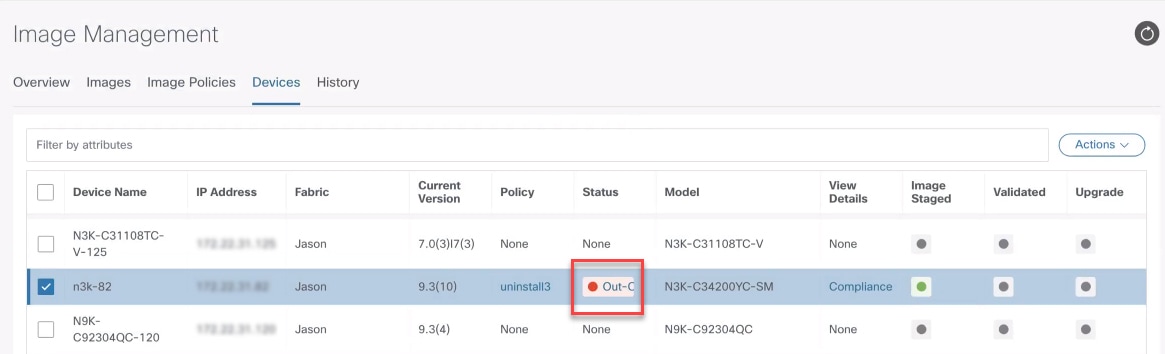 |
||
|
Step 14 |
In the Image Version Status dialog box, it shows the packages that will be removed. |
||
|
Step 15 |
To remove the packages, in the Devices window, make sure the checkmark is placed in the checkbox for the devices you want to remove the packages from. |
||
|
Step 16 |
From the Actions drop-down list, select Upgrade. |
||
|
Step 17 |
In the Upgrade/Uninstall window, enter the following:
|

 Feedback