New and Changed Information
The following table provides an overview of the significant changes up to this current release. The table does not provide an exhaustive list of all changes or of the new features up to this release.
|
Release Version |
Feature |
Description |
|---|---|---|
|
NDFC release 12.1.1 |
Initial release of this use case document. |
Initial release of this use case document. |
Understanding Shared Border with Nexus Dashboard Fabric Controller
Generally, the way that shared border is implemented with Cisco Nexus Dashboard Fabric Controller (NDFC) is similar to the description of a shared border provided in the Shared border section in the VXLAN EVPN Multi-Site Design and Deployment White Paper. The following figure is used in that white paper, and is also useful here when describing how shared border is implemented in NDFC.
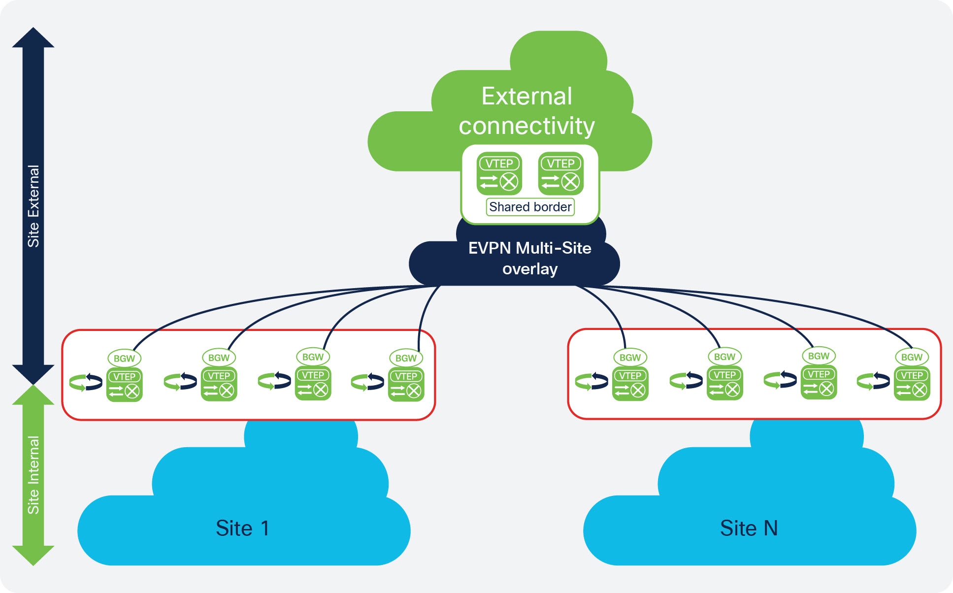
To better understand the benefits of a shared border, first assume that you have a single, physical data center with hundreds or thousands of switches. Having all of those switches in a single site, or inside a single fabric, could cause issues within the fabric, where one or two failed switches could affect the stability of the network.
One solution to that problem is to divide that physical data center into separate sites, as shown with the blue clouds in
the lower part of the example topology shown (Site 1 and Site N). It's still a single physical location, but splitting that single physical data center into separate sites allows you to
make your network as resilient as possible. When you separate the data center into separate sites correctly, if you have to
take down one site for maintenance, the applications and services available in the remaining sites are unaffected.
With your data center split into separate sites, however, you now have to consider how the following traffic will flow:
-
East-west traffic: Using the example topology shown above, assume there's an application in Site 1, and there's another application in Site N, and these two applications want to communicate with each other. Typically, this can be accomplished by connecting the two sites using Multi-Site, as shown with the blue
EVPN Multi-Site overlaycloud in the example topology above. -
North-south traffic: The applications in Site 1 and Site N now need to connect to the Internet, as shown with the green
External Connectivitycloud in the example topology above. Typically, this can be accomplished using a set of border devices, or border gateways, that allow you to connect your individual sites to the Internet, as shown with the green border boxes in the example topology above.
However, additional considerations come into play when configuring the north-south traffic from the individual sites to the Internet, such as where to position firewalls and load balancers, how to set up a common ingress and egress point for traffic between the sites and the Internet, and so on. Certain options for setting up these north-south connections can become cumbersome or expensive, such as setting up separate, individual connections from each site to the Internet, which would require networking hardware for each site and might not allow for the necessary redundancy between sites.
One option that solves these issues, where there is redundancy between sites while also providing a cost-effective way of
connecting each site to the Internet, is by using shared services through a shared border. Border topology is commonly used
in the latest deployments, where you would build hierarchical multi-cloud architectures and you would want to have a common
plane for the north-to-south traffic. This provides a deterministic behavior rather than having a single point of failure
and undeterministic behavior between sites, such as the blue Site 1 and Site N in the lower part of the example topology above.
In this type of configuration, a set of devices (such as the two green VTEP boxes in the Shared border box in the example topology shown above) handle any services that are required, such as firewall inspection, load balancing,
Layer 4 to Layer 7 services, VRF Lite connectivity from the data center to the cloud, and so on. This configuration allows
you to share these services through these devices, while also providing a means to cross the "border" from the internal sites
(the blue Site 1 and Site N in the lower part of the example topology above) to the Internet (the green External connectivity cloud in the example topology), which is why this feature is called a shared border.
Example Topology and NDFC Configuration
For this shared border use case, we will use the following topology and NDFC configuration as examples:
Example Topology
We will use the following topology from the Shared border section of the VXLAN EVPN Multi-Site Design and Deployment White Paper as an example topology for this shared border use case.
Example NDFC Configuration
We will use the following NDFC configuration as an example starting point for this shared border use case.
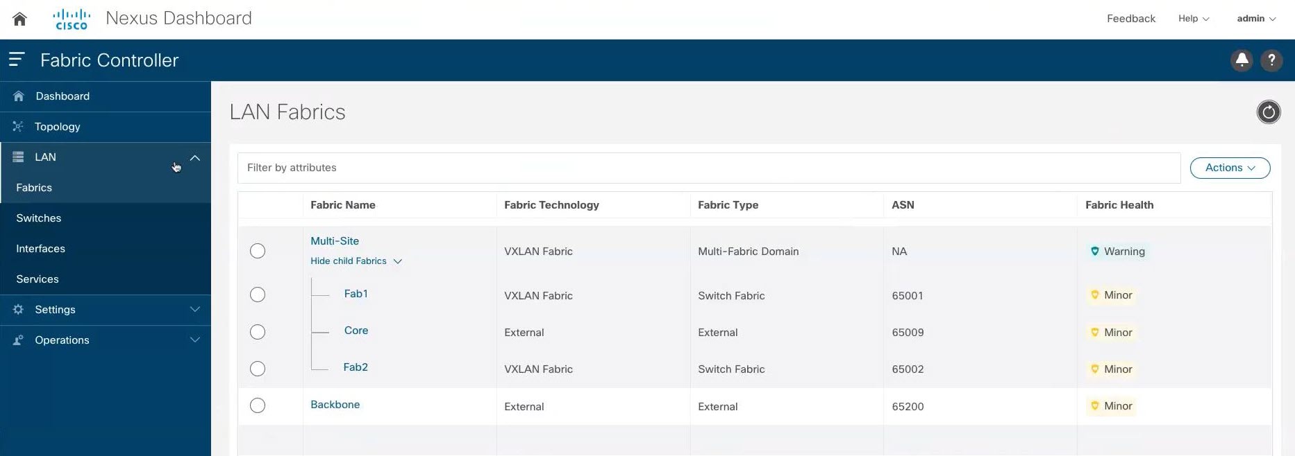
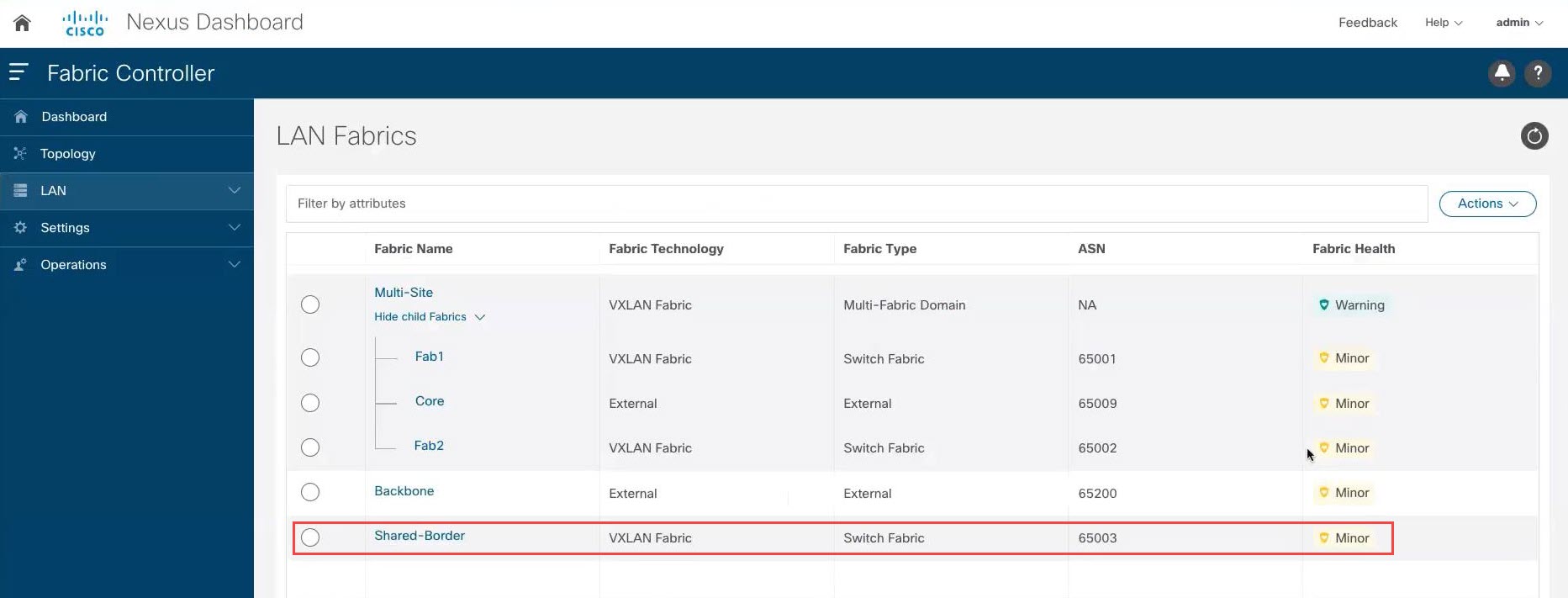
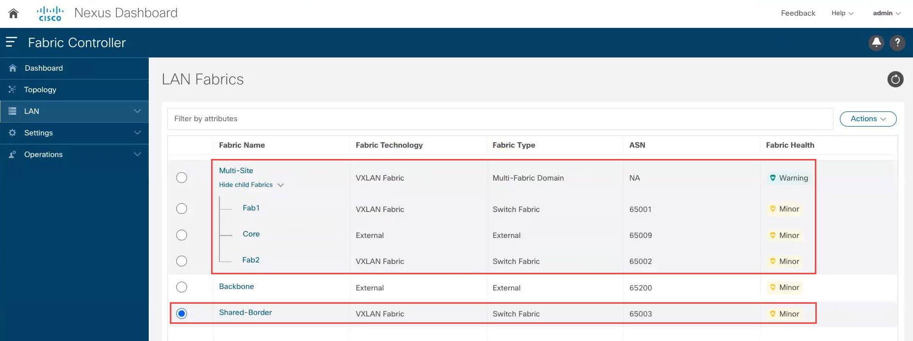
In this example NDFC configuration, we have the following items already configured:
-
Two VXLAN fabrics (
Fab1andFab2in the example screenshot above) -
A route server (
Corein the example screenshot above) -
A backbone that is an external site where you have VRF Lite connectivity configured to the Internet (
Backbonein the example screenshot above)
Mapping the example topology shown in Example Topology with the example NDFC configuration shown above:
-
Site 1in the example topology maps toFab1in the example NDFC configuration above -
Site Nin the example topology maps toFab2in the example NDFC configuration above -
The blue
EVPN Multi-Site overlaycloud in the example topology maps toCorein the example NDFC configuration above -
The green
External connectivitycloud in the example topology maps toBackbonein the example NDFC configuration above
Note that the shared border box that is shown in Example Topology is not currently mapped to anything in the example NDFC configuration above; this is the piece that we will be configuring in this use case.
It is important to note that all of the fabrics (clouds) shown in Example Topology are assigned different BGP autonomous system numbers (BGP ASNs) in the example NDFC configuration above:
-
Fab1has a BGP ASN of 65001 (which maps toSite 1in the example topology) -
Fab2has a BGP ASN of 65002 (which maps toSite Nin the example topology) -
Corehas a BGP ASN of 65009 (which maps toEVPN Multi-Site overlayin the example topology) -
Backbonehas a BGP ASN of 65200 (which maps toExternal connectivityin the example topology)
The new shared border fabric that you will be configuring using these procedures will also have a unique BGP ASN.
Guidelines and Limitations
Following are the guidelines and limitations when configuring the shared border in Cisco Nexus Dashboard Fabric Controller:
-
If you are configuring a Layer 3 extension from the shared border fabric to other fabrics and you using a multicast underlay, you will also need to add a loopback for each overlay VRF on the shared borders and on all border gateways.
-
When a shared border fabric is configured with Multicast as the replication mode and is moved to a multi-site domain (MSD), the corresponding underlay and overlay Inter-Fabric Connections (IFCs) are created and any VRFs and networks that are already present in the MSD will also be inherited. In an MSD that already has existing VRFs and networks, it is disruptive if you have to detach them before you change the shared border fabric replication mode from Multicast to Ingress. In addition, changing the replication mode from Multicast to Ingress on a shared border fabric is not allowed if there are existing VRFs, networks and IFCs, as this will generate an error. Therefore, we recommend that you set the replication mode for the shared border fabric to Ingress before you move it to the MSD.
Configuring a Shared Border
Follow the procedures in these sections to configure a shared border.
Create a VXLAN Fabric for the Shared Border
For more detailed instructions, see the "Creating VXLAN EVPN Fabric" section in the Cisco NDFC-Fabric Controller Configuration Guide, release 12.1.1e or later (for example, Creating VXLAN EVPN Fabric in Cisco NDFC-Fabric Controller Configuration Guide, Release 12.1.1e).
Procedure
|
Step 1 |
In NDFC, click LAN in the left nav bar. The already-configured LAN fabrics are displayed. |
|
Step 2 |
Click . 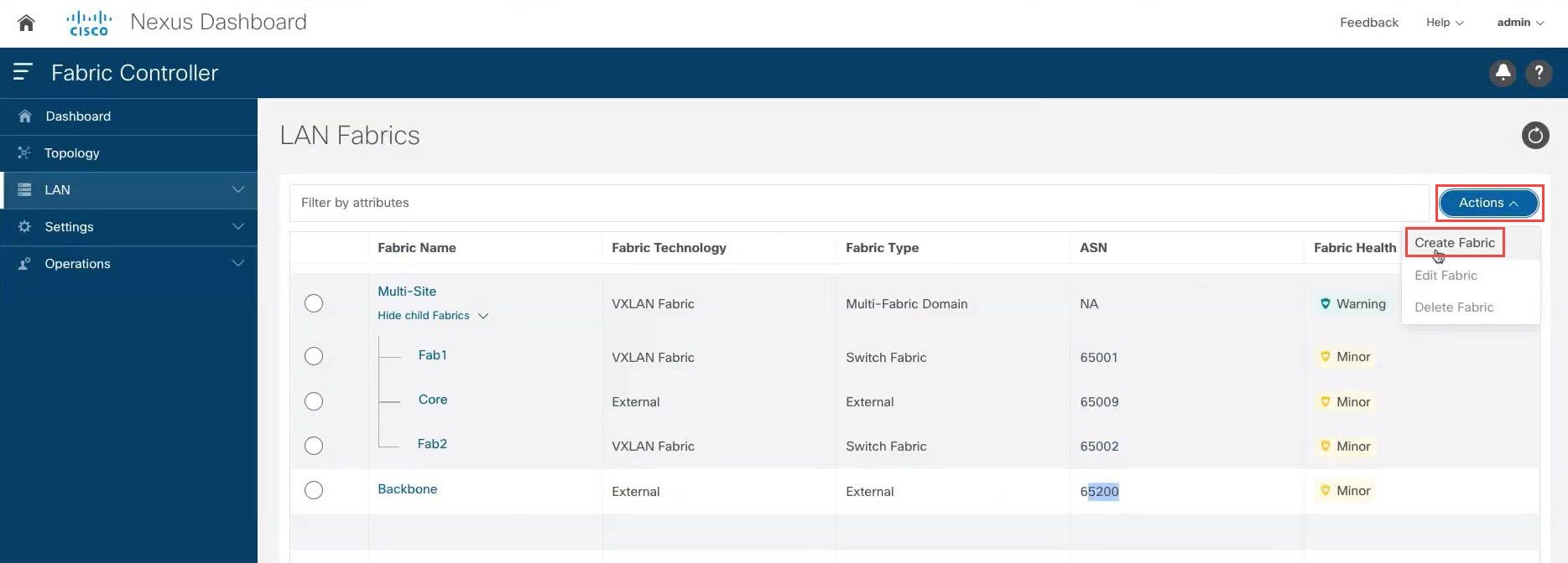
|
|
Step 3 |
In the Create Fabric screen, enter a name for the new fabric (for example, |
|
Step 4 |
Choose the |
|
Step 5 |
In the General Parameters tab in the For this use case, we will use 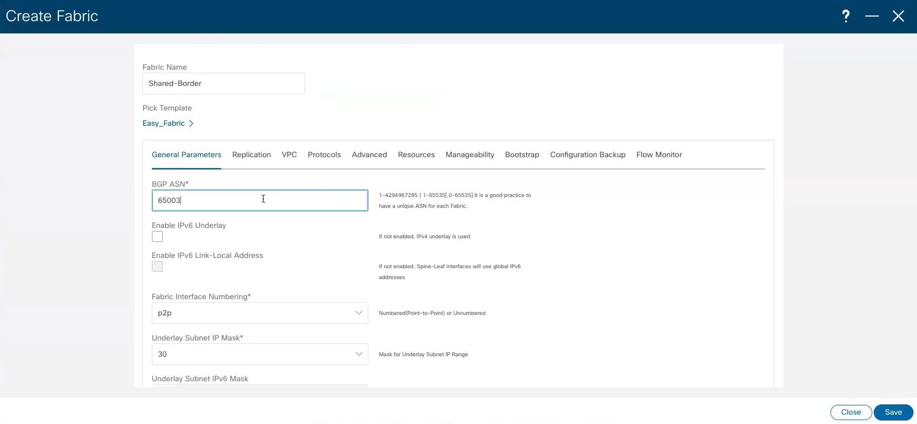
|
|
Step 6 |
Make any additional configurations to the shared border fabric template, if necessary. For example, it's good practice to enter unique values for the Underlay Routing Loopback IP Range and Underlay VTEP Loopback IP Range fields under the Resources tab to proactively avoid duplicate IDs across individual fabrics once you've connected them through multi-site. |
|
Step 7 |
When you have completed the necessary configurations to the shared border fabric template, click Save. The LAN Fabric page appears again, with the newly-created shared border fabric added to the list of configured fabrics.
|
What to do next
Follow the procedures in Add Switches in the Shared Border Fabric.
Add Switches in the Shared Border Fabric
For more detailed instructions, see the "Adding Switches and Transitioning VXLAN Fabric Management to NDFC" section in the Cisco NDFC-Fabric Controller Configuration Guide, release 12.1.1e or later (for example, Adding Switches and Transitioning VXLAN Fabric Management to NDFC in Cisco NDFC-Fabric Controller Configuration Guide, Release 12.1.1e).
Before you begin
Complete the procedures in Create a VXLAN Fabric for the Shared Border before beginning these procedures.
Procedure
|
Step 1 |
In NDFC, double-click the newly-created shared border fabric. The Overview page for the shared border fabric appears. |
|
Step 2 |
Click the Switches tab, then click . 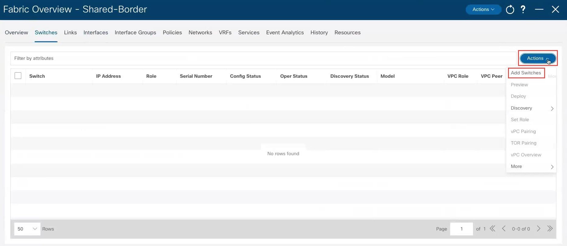
|
|
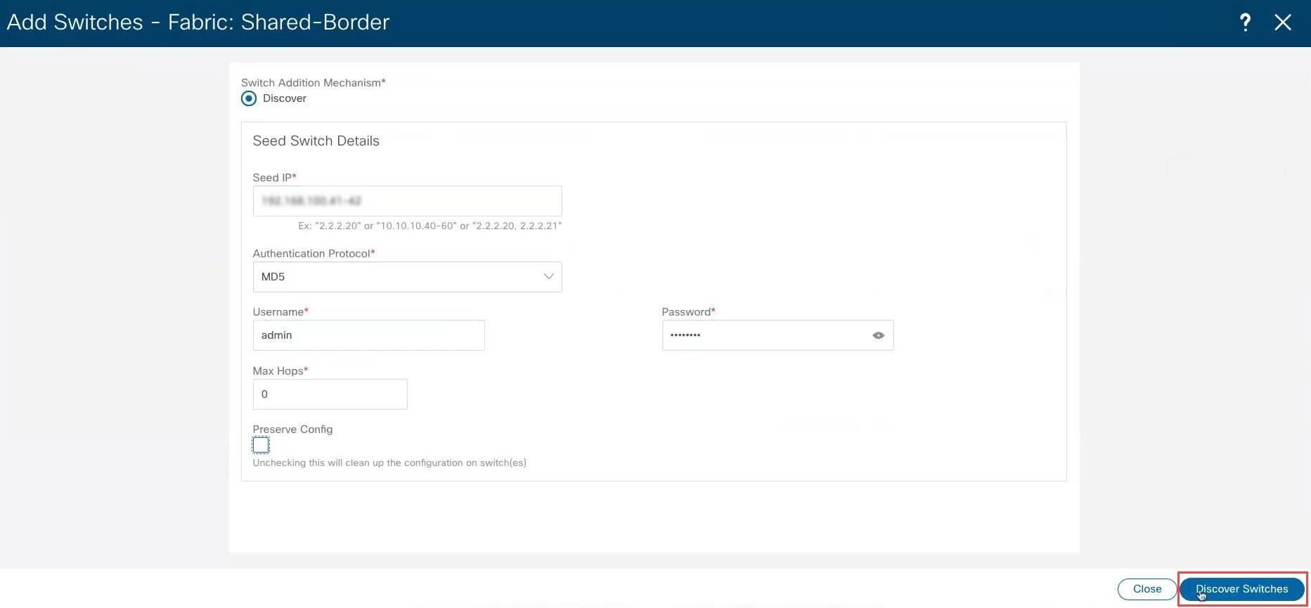
Step 3 |
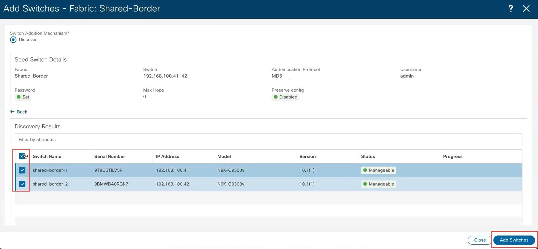
Make the necessary configurations to add the switches.
|
|
Step 4 |
After the discovery process is finished for the switches, navigate back to the Switches tab, if necessary. |
|
Step 5 |
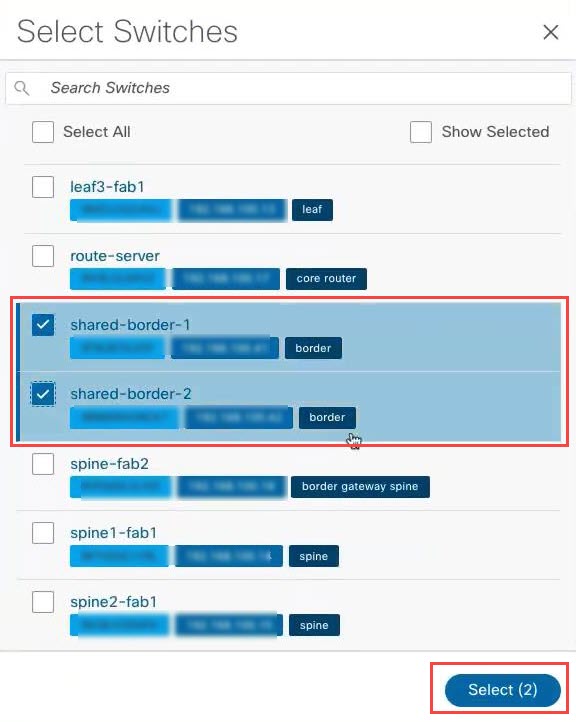
Click the box next to Switch to select all of the newly-discovered switches and click . 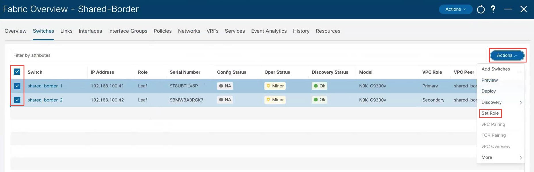
|
|
Step 6 |
Choose Border from the list of roles for the switches, then click Select. 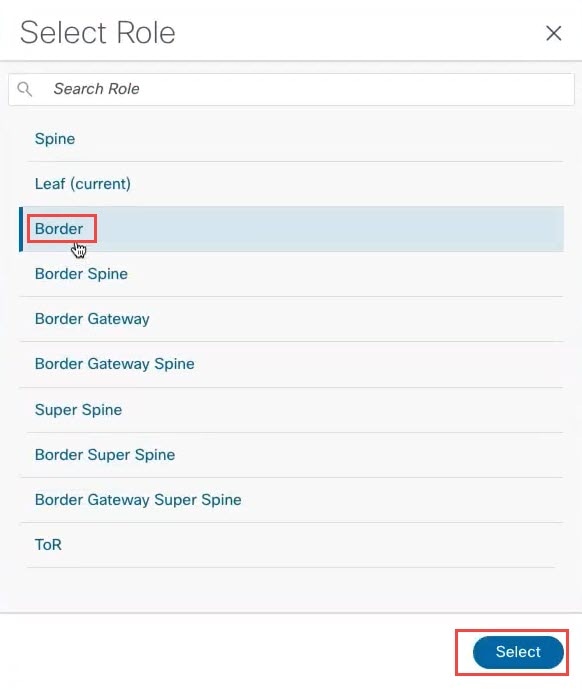
Click Ok in the warning popup that appears. |
|
Step 7 |
Wait for the Discovery Status to show as Ok for the switches. The discovery process might take roughly 5 minutes. After several minutes, you can manually rediscover the switches if necessary by clicking the box next to Switch to select all of the newly-discovered switches, then clicking . 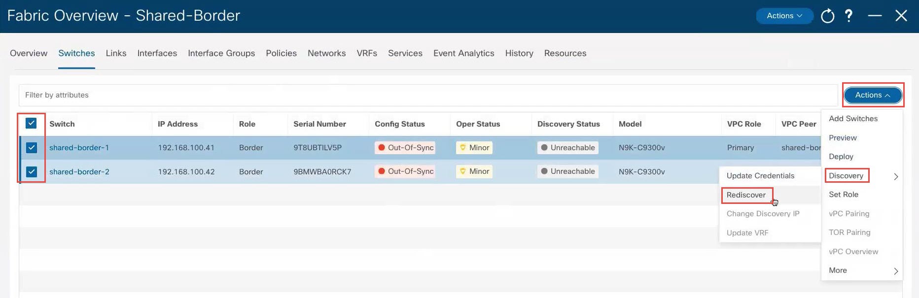
After a few moments, the Discovery Status will show as Ok; however, the Config Status will still show as Out-Of-Sync. |
|
Step 8 |
At the top of the page, click . 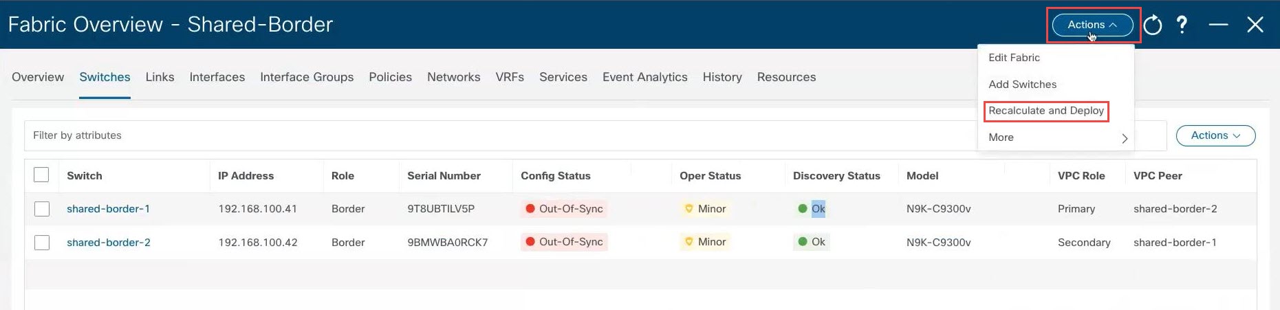
|
|
Step 9 |
When the recalculation process is completed, click Deploy All, then click Close in the Deploy Progress screen when the deployment is completed. |
|
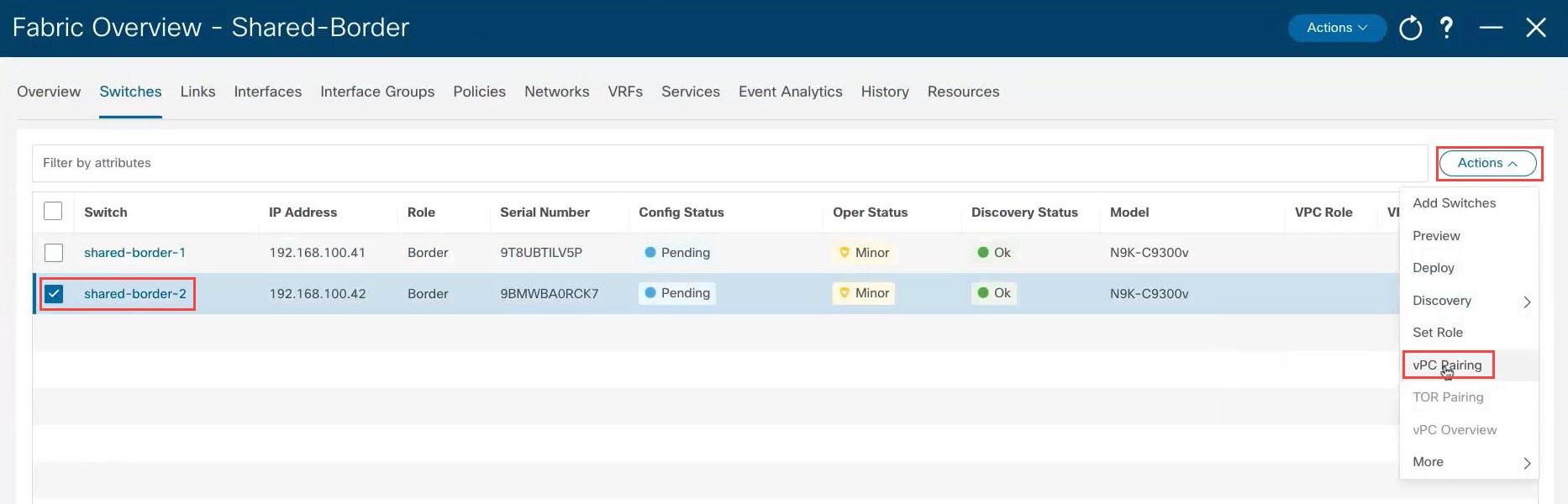
Step 10 |
If necessary, configure vPC pairing between the two switches. This is an optional step, but you might want to configure vPC pairing for high availability if you have two border devices that are connected back-to-back. To configure vPC pairing:
|
|
Step 11 |
Wait for the status shown in the Config Status column to change to the green Success and In-Sync status. This means that the configuration that is present on NDFC complies with the configuration that is on the switches. 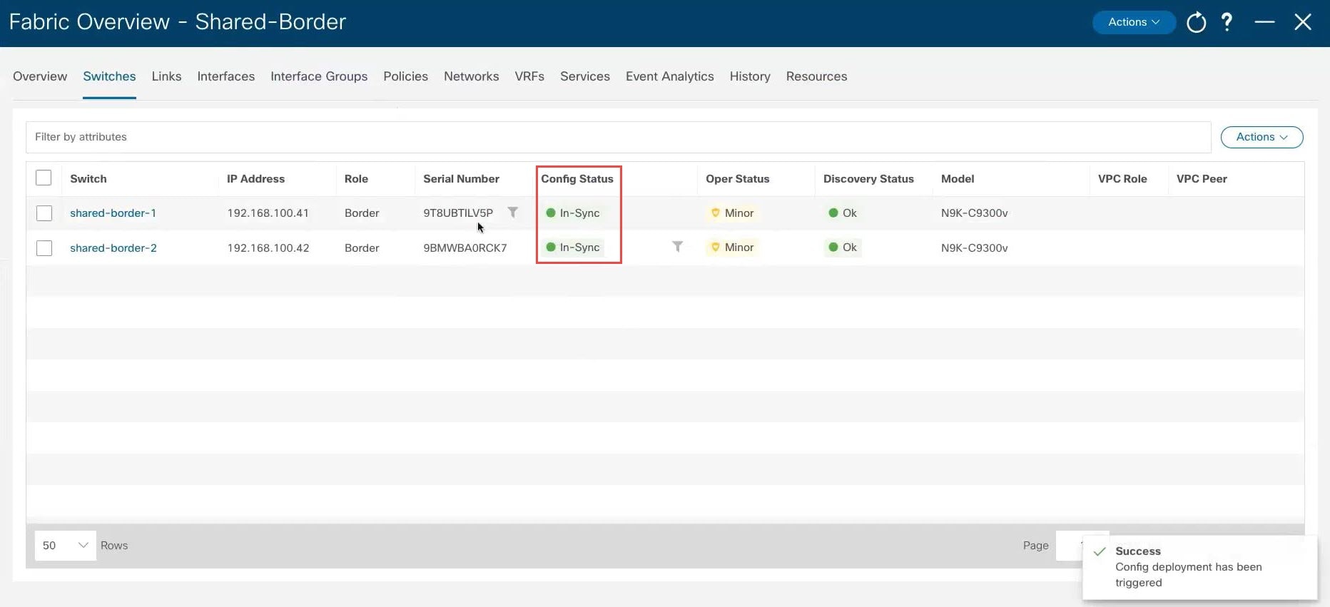
|
What to do next
At this point in the process, the configuration for the green shared border box shown in Example Topology and NDFC Configuration is complete. The next step in the process is to add the shared border fabric into the Multi-Site container using the procedures in Add the Shared Border Fabric into the Multi-Site Domain.
Add the Shared Border Fabric into the Multi-Site Domain
In the example topology that we are configuring for this use case, you created a VXLAN fabric for the shared border and you added the necessary switches in the shared border fabric. However, at this point in the process, the new shared border fabric is still outside of the multi-site domain, as shown below.
In the example configuration shown above, the Fab1 and Fab2 VXLAN fabrics, and the external fabric Core, are all child fabrics within the multi-site domain (the multi-fabric domain with the fabric name Multi-Site). However, the Shared Border VXLAN fabric is still outside of the multi-site domain.
The procedures in this section describe how to add the shared border fabric into the multi-site domain. In the example topology
shown in Example Topology, these procedures essentially add the Shared border area in green within the blue EVPN Multi-Site overlay cloud below it.
Before you begin
Complete the procedures in Add Switches in the Shared Border Fabric before beginning these procedures.
Procedure
|
Step 1 |
In NDFC, double-click the The Overview page for the |
|
Step 2 |
Click the Child Fabrics tab. The child fabrics that are currently within the multi-site domain are listed.
|
|
Step 3 |
Click . 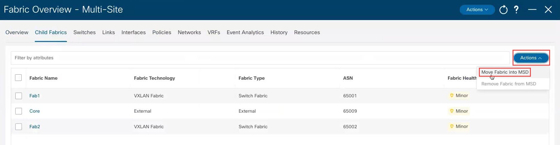
Child fabrics that are not currently within the multi-site domain are listed. |
|
Step 4 |
Select the shared border fabric that you created and click Select. 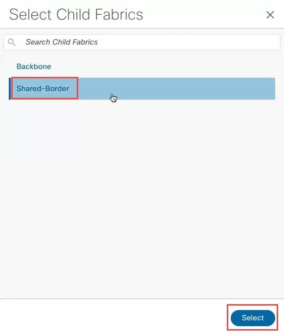
|
|
Step 5 |
Click Ok in the warning window that appears. The warning window tells you to perform a |
|
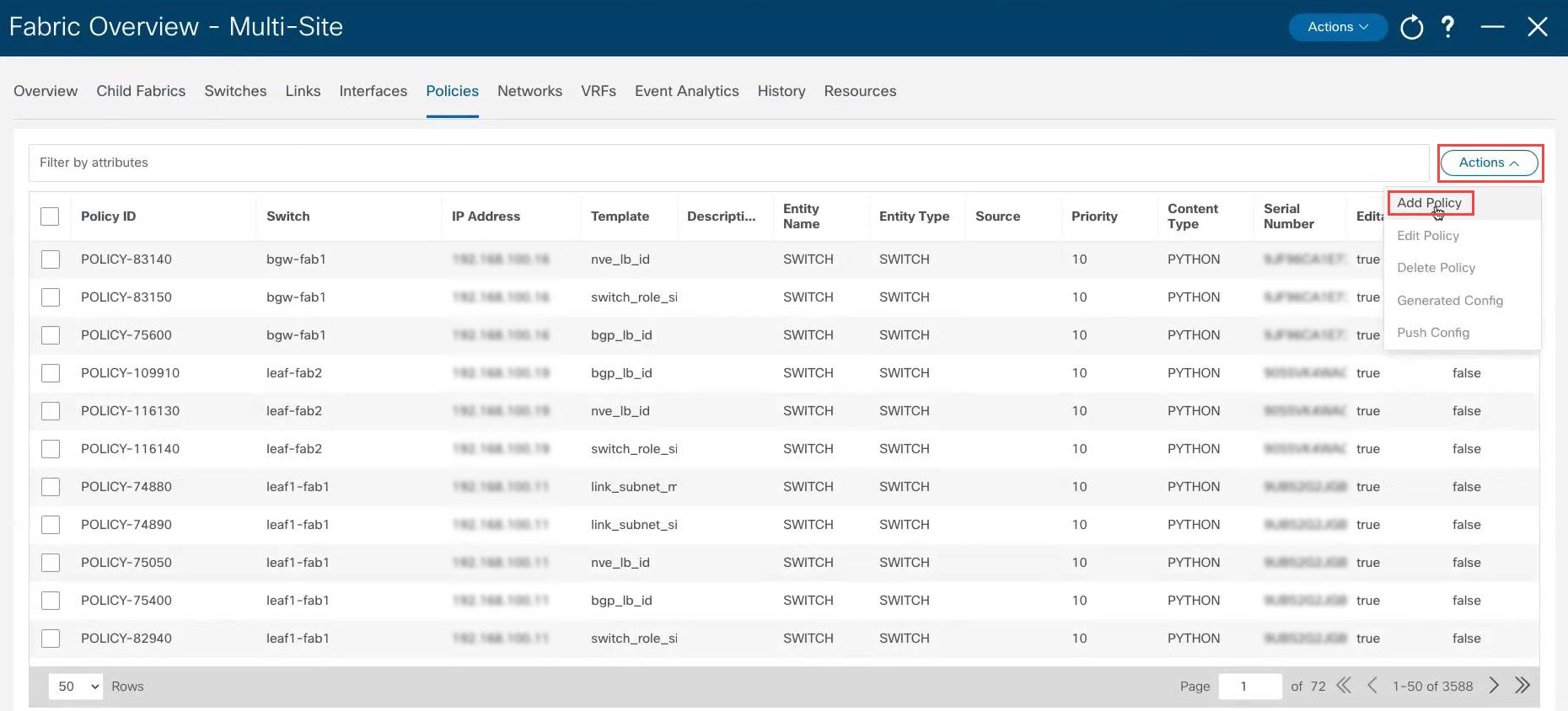
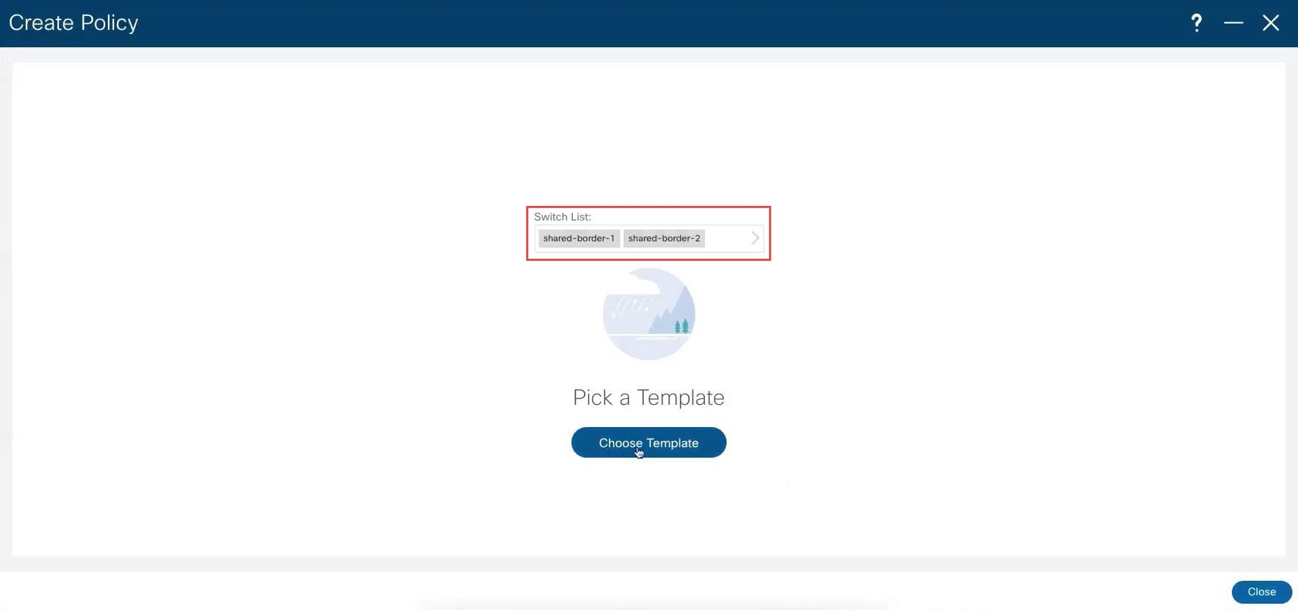
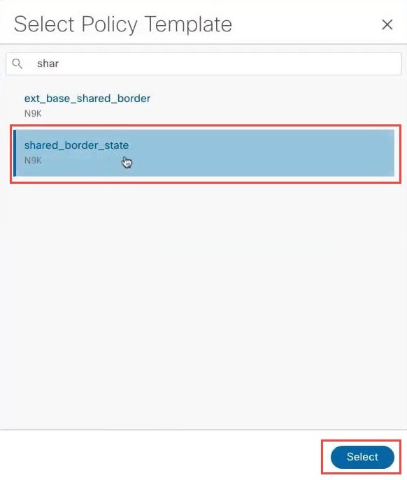
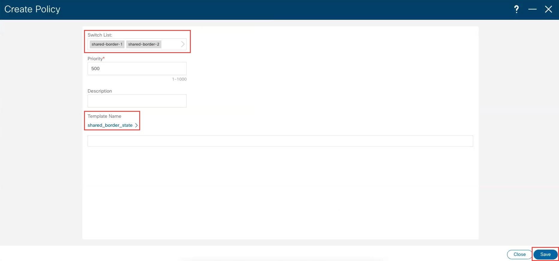
Step 6 |
Add the necessary policy to allow NDFC to deploy the VXLAN EVPN multi-site configuration on the shared border switches. By default, NDFC deploys the VXLAN EVPN multi-site configuration on switches with the role of border gateway or core router. NDFC does not deploy the configuration on any switch that does not have a role of border gateway or core router, even if those devices are part of the multi-site domain. In this shared border use case, we want to make sure that NDFC automates the VXLAN EVPN multi-site underlay and overlay configuration, along with the rest of the devices. This step adds the necessary policy so that NDFC deploys the VXLAN EVPN multi-site configuration on the shared border switches.
|
|
Step 7 |
Click the Child Fabrics tab to verify that the shared border fabric was added within the multi-site domain successfully. |
|
Step 8 |
At the top of the page, click . 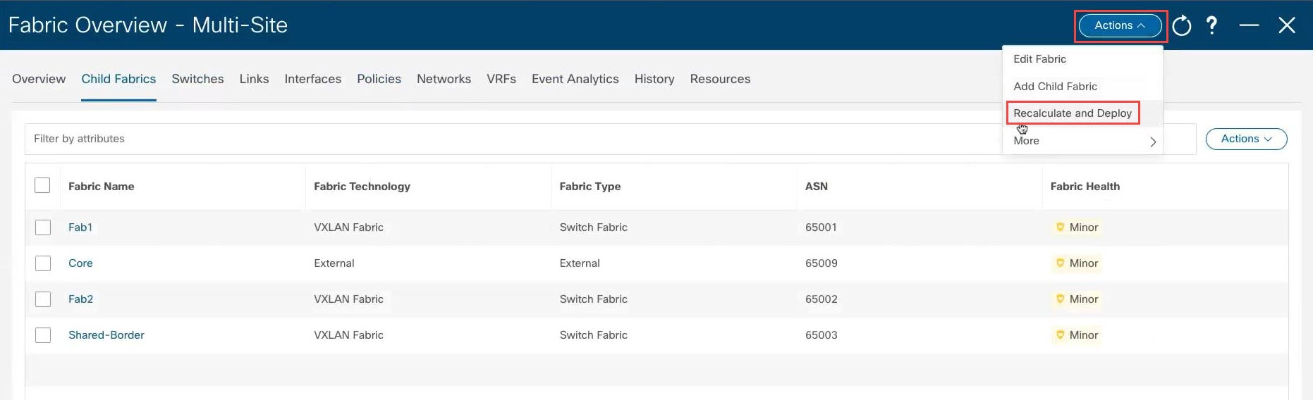
|
|
Step 9 |
When the recalculation process is completed, click Deploy All, then click Close in the Deploy Progress screen when the deployment is completed. |
|
Step 10 |
In the Child Fabrics page, click the shared border fabric. The overview page for the shared border fabric appears. |
|
Step 11 |
Click the Switches tab. The shared border switches that you configured earlier are displayed. |
|
Step 12 |
At the top of the page, click . This step is mandatory. It is important to perform this step so that it generates the correct loopback configuration in certain situations, such as if you configured vPC pairing between the border switches in a previous step. 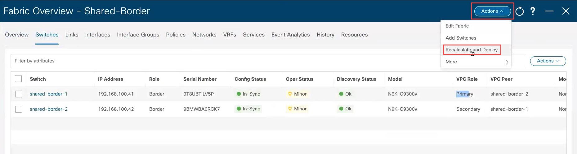
|
|
Step 13 |
When the recalculation process is completed, click Deploy All, then click Close in the Deploy Progress screen when the deployment is completed. |
What to do next
Extend the Layer 3 services VRF from the shared border fabric to the external fabric, if necessary, using the procedures in Extend the Layer 3 Services VRF from the Shared Border Fabric to the External Fabric.
Optional Tasks
The following sections provide information on optional follow-up tasks that you can perform, if desired, after you have configured the shared border in NDFC.
Extend the Layer 3 Services VRF from the Shared Border Fabric to the External Fabric
Looking at the figure shown in Example Topology, after completing the procedures in the previous sections, you should now have configured everything from the green Shared border area down, where the green Shared border area is now connected to the blue EVPN Multi-Site overlay cloud (everything below the blue EVPN Multi-Site overlay cloud should have been configured previously).
In this section, you will configure the connection from the green Shared border area going up, to the green External connectivity cloud. Looking at the example NDFC configuration for this use case, as shown in Example NDFC Configuration, the green External connectivity cloud has already been configured (the Backbone fabric shown in Example NDFC Configuration). These procedures describe how to connect the external Backbone fabric (the green External connectivity cloud shown in Example Topology) to the shared border fabric (the green Shared border area shown in Example Topology).
Procedure
|
Step 1 |
In NDFC, click LAN in the left nav bar. The already-configured LAN fabrics are displayed. Note that the 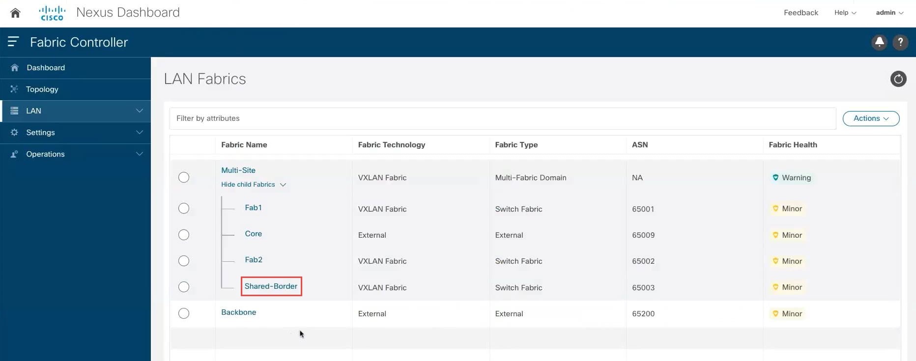
|
|
Step 2 |
Configure a VRF Lite connection between the shared border fabric and the external fabric. See the "VRF Lite" chapter in the Cisco NDFC-Fabric Controller Configuration Guide, release 12.1.1e or later, for those procedures (for example, VRF Lite in Cisco NDFC-Fabric Controller Configuration Guide, Release 12.1.1e). |
Configure for Layer 2 Extension
As mentioned previously, the description of shared border provided in the Shared border section in the VXLAN EVPN Multi-Site Design and Deployment White Paper is also applicable when understanding how shared border is implemented with NDFC. However, additional information is necessary here for the following paragraph from that document:
The shared border operates like a traditional VTEP, but unlike the site-internal VTEPs discussed previously, the shared border is a site-external VTEP. In the case of external connectivity, the shared border operates solely in Layer 3 mode, and hence no BUM replication between the BGW and shared border nodes is necessary.
The paragraph above is applicable for the most common use case for a shared border, which is a Layer 3 handoff. However, in
another example scenario, an application in a site (for example, Site 1 or Site N in the Example Topology) wants to communicate with a branch office or some other data center and needs to go through a firewall or load balancer,
but that firewall or load balancer is connected to the shared border. In this case, you would also have to configure Layer
2 BUM replication. In other words, you would need Layer 2 as well as Layer 3 in this situation.
If Layer 2 is also required for your situation, you will have to change the replication mode for the shared border fabric
from Multicast to Ingress. This is because the DCI interface on the border gateways (the green BGW boxes in the example topology shown in Example Topology) only support ingress replication; they do not support multicast through NDFC.
Follow these procedures to change the replication mode for the shared border fabric from Multicast to Ingress if Layer 2 extension is required from the VXLAN EVPN border gateway fabrics to the VXLAN shared border fabrics.
 Note |
Changing the replication mode is not supported if any VRF or network is attached and deployed on devices that are part of this fabric. You must detach the VRF or network before changing the replication mode in this case. |
Procedure
|
Step 1 |
In NDFC, click LAN in the left nav bar. The already-configured LAN fabrics are displayed. |
|
Step 2 |
Click the shared border fabric that you configured previously. The Overview page for the shared border fabric is displayed. |
|
Step 3 |
Click . The Edit Fabric page for the shared border fabric is displayed. |
|
Step 4 |
Click the Replication tab, then locate the Replication Mode area and choose Ingress in this area. 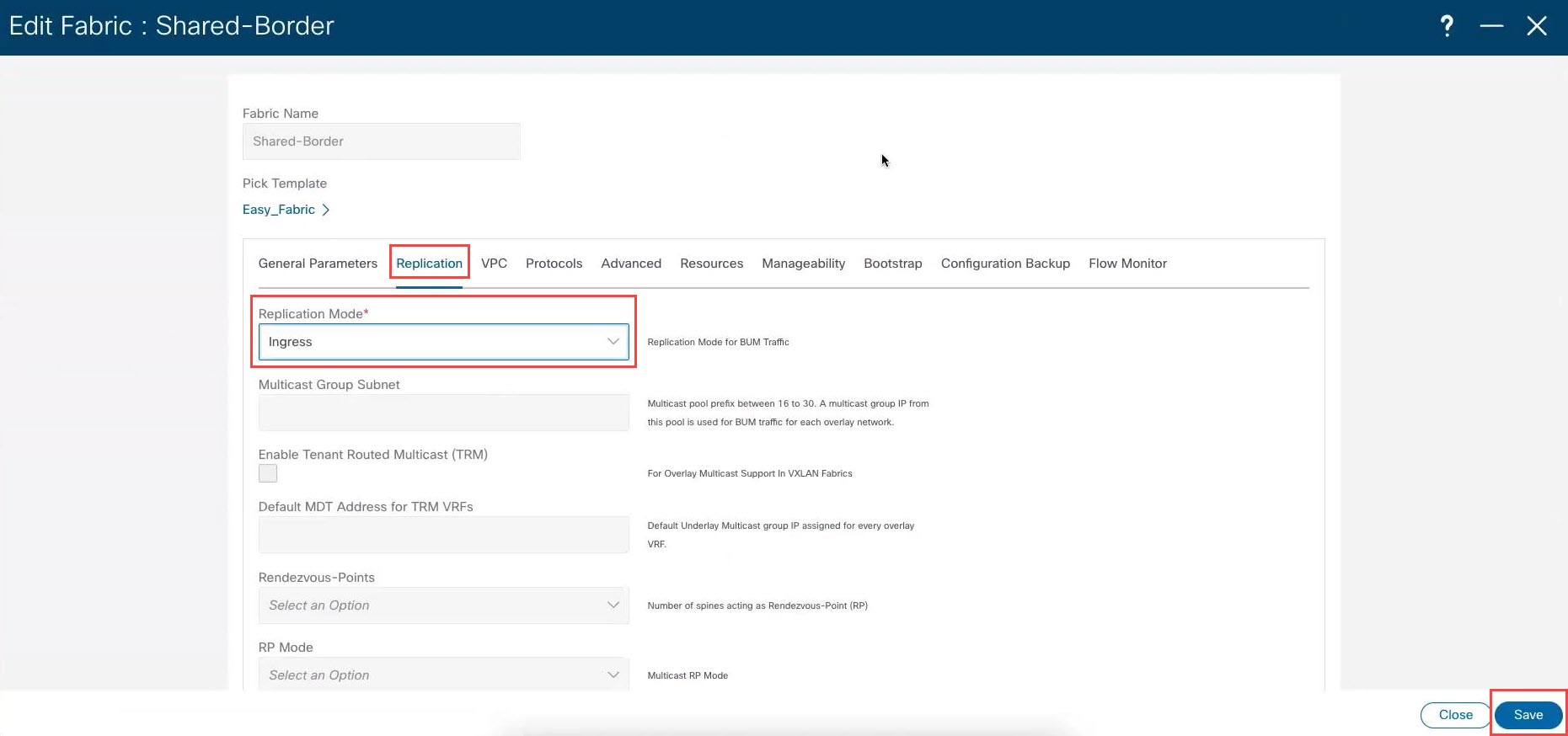
|
|
Step 5 |
Click Save. |
 Feedback