Cisco Modeling Labs Corporate Edition User Guide, Release 1.1
Bias-Free Language
The documentation set for this product strives to use bias-free language. For the purposes of this documentation set, bias-free is defined as language that does not imply discrimination based on age, disability, gender, racial identity, ethnic identity, sexual orientation, socioeconomic status, and intersectionality. Exceptions may be present in the documentation due to language that is hardcoded in the user interfaces of the product software, language used based on RFP documentation, or language that is used by a referenced third-party product. Learn more about how Cisco is using Inclusive Language.
- Updated:
- September 29, 2015
Chapter: Build a Configuration
- Build a Configuration Overview
- Create and Modify a Node Configuration
- Create a Node Configuration Manually
- Use an Existing Node Configuration
- Import the Configuration from a Cariden MATE File
- Import the Configuration from a Visio vsdx File
- Create Node and Interface Configurations Using AutoNetkit
- Assign VLANs
- Use a Managed Switch
- Set Firewall Capabilities
- Set Security Levels
- Configure GRE Tunnels
Build a Configuration
Build a Configuration Overview
In the build phase, you build the configurations for each node. After selecting the options for the overall topology and each node, you create the configuration files. Alternatively, you can use AutoNetkit to create the configuration files.
You can modify and save configuration files for the topology and for each node in your topology.
Create and Modify a Node Configuration
While AutoNetkit is useful for generating configuration files for all the nodes in the topology, you can bypass AutoNetkit and enter node configuration information directly.
You can enter configuration information in either of the following ways:
-
During the design phase, copy and paste configuration commands for each node.
-
During the simulation phase, connect to a node console and change its configuration when the topology is running. See the chapter Simulate the Topology for more information on how to modify, extract, and save a running configuration.
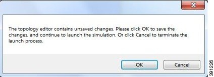
While in the Design perspective, any changes you manually make to a node configuration are saved in the current filename .virl file. Before you launch a simulation from the Design perspective, a notification window advises you to save the changes or cancel the simulation launch.
Create a Node Configuration Manually
The topology design should be complete.
| Step 1 | In the Topology Editor, click a node. | ||||
| Step 2 | In the
Properties view, click
AutoNetkit and
uncheck the
Auto-generate the configuration
based on these attributes check box.
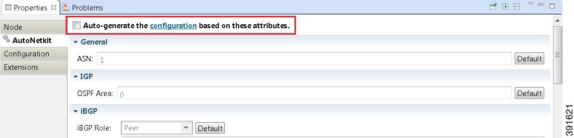 | ||||
| Step 3 | Click the Configuration tab. | ||||
| Step 4 | Enter the
configuration commands in the
Configuration view.
|
Use an Existing Node Configuration
You can use an existing configuration file to create a node configuration in Cisco Modeling Labs.
The topology design should be complete.
What to Do Next
Launch a simulation to observe the changes.
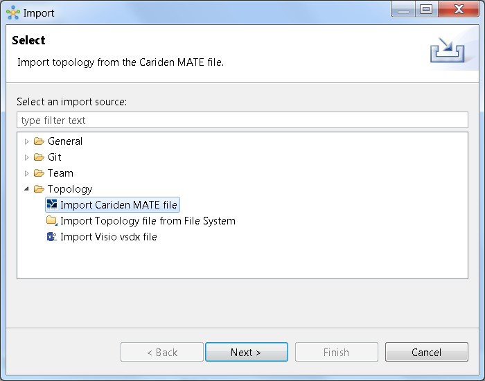
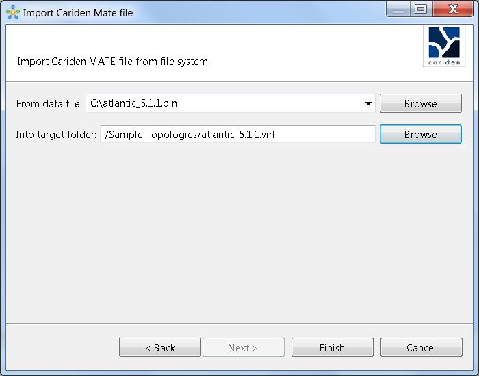
Import the Configuration from a Cariden MATE File
You can import a topology from an existing Cariden MATE file, version 5.2.0 or later or version 6.1.0. Cisco Modeling Labs client will accept site imports up to two layers deep. Any Cariden MATE file that has a topology with more than two layers of sites will not import correctly.
Export the Configuration to Cariden MATE File
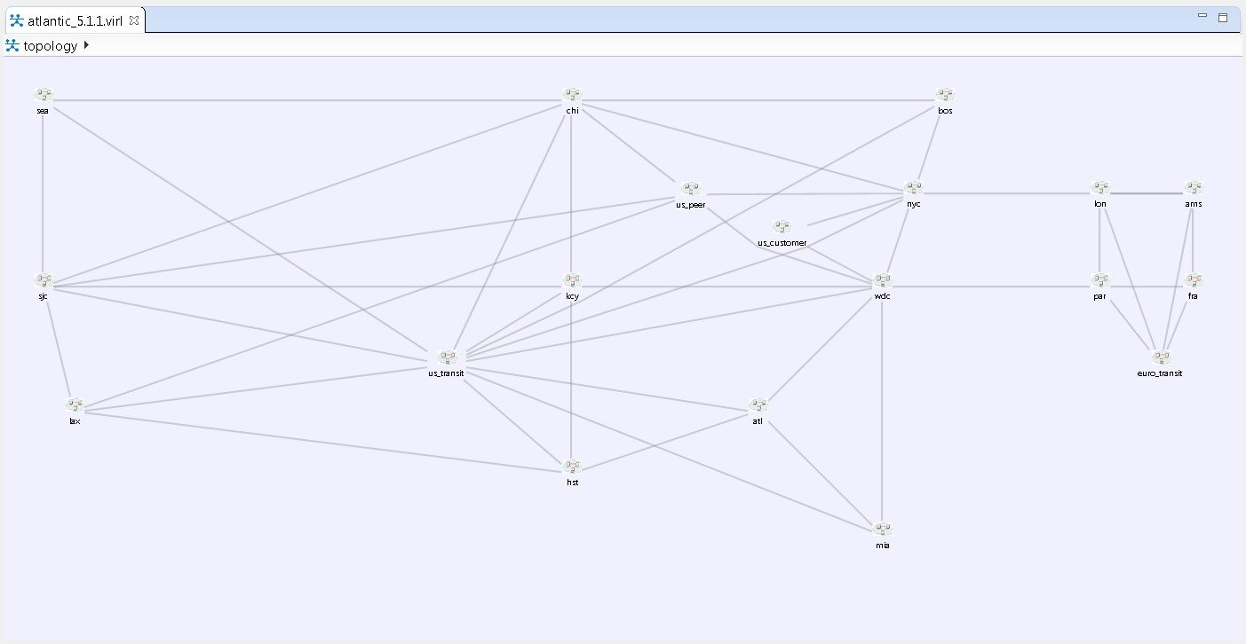
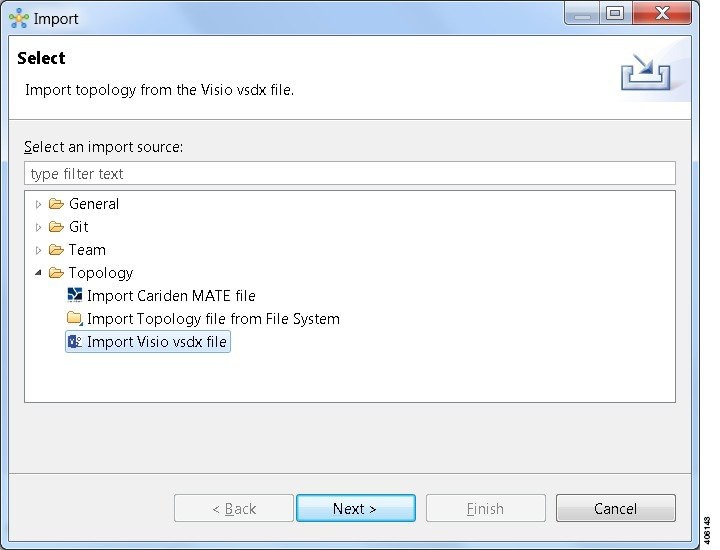
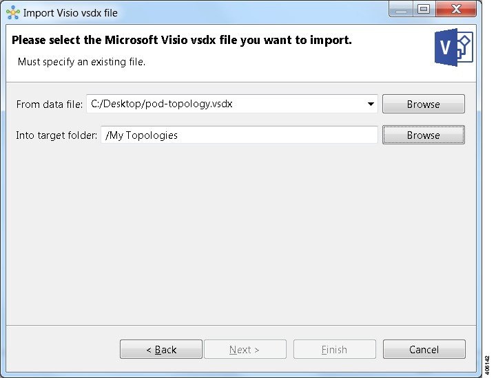
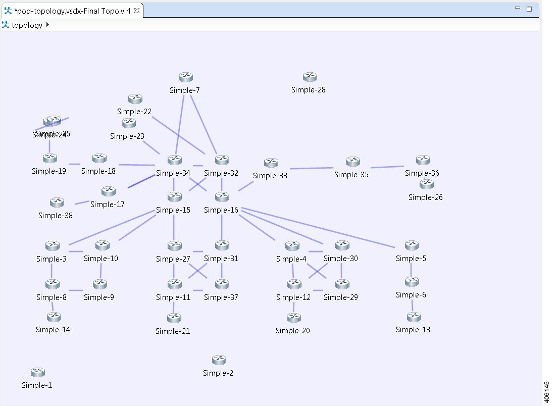
Import the Configuration from a Visio vsdx File
You can import a topology from an existing Visio .vsdx file, version 2013 and later.
Export the Configuration to SVG Files
For this release of Cisco Modeling Labs, export to Visio .vsdx files is not supported. However, export to .svg files is supported, as Visio supports the use of .svg files. The Export option can be used to export .virl files as .svg files.
| Step 1 | Choose . A window appears, prompting you to Export to SVG file. |
| Step 2 | Choose Export to SVG file then click Next. |
| Step 3 | Choose the location To file for the SVG file export. Use Browse to select the target Project folder. |
| Step 4 | Enter a filename for the exported SVG file, or use the default filename. For example, sample_topology.virl is converted to sample_topology.svg and saved in the target directory. |
| Step 5 | Click Finish. The Cisco Modeling Labs .virl file silently converts to a SVG .svg file. |
Create Node and Interface Configurations Using AutoNetkit
The topology design should be complete.
| Step 1 | Verify the
configuration for each node in the topology.
| ||
| Step 2 | Generate a configuration for the topology. Click Build Initial Configurations from the toolbar. Alternatively, from the menu bar, choose . You are prompted to save any changes made since the previous configuration update. If the Auto-generate the configuration based on these attributes check box is checked for a node, the configuration updates are generated by AutoNetkit. | ||
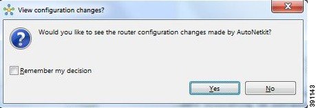
| Step 3 | AutoNetkit
displays a notification after it generates the configuration. Click
No to skip
a comparison of configuration changes. Click
Yes to
open a comparison view of the configuration changes.
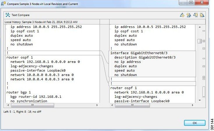 | ||
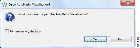
| Step 4 | When you close
the comparison view, a notification is displayed, and you can choose whether or
not to open AutoNetkit visualization.
|
Assign VLANs
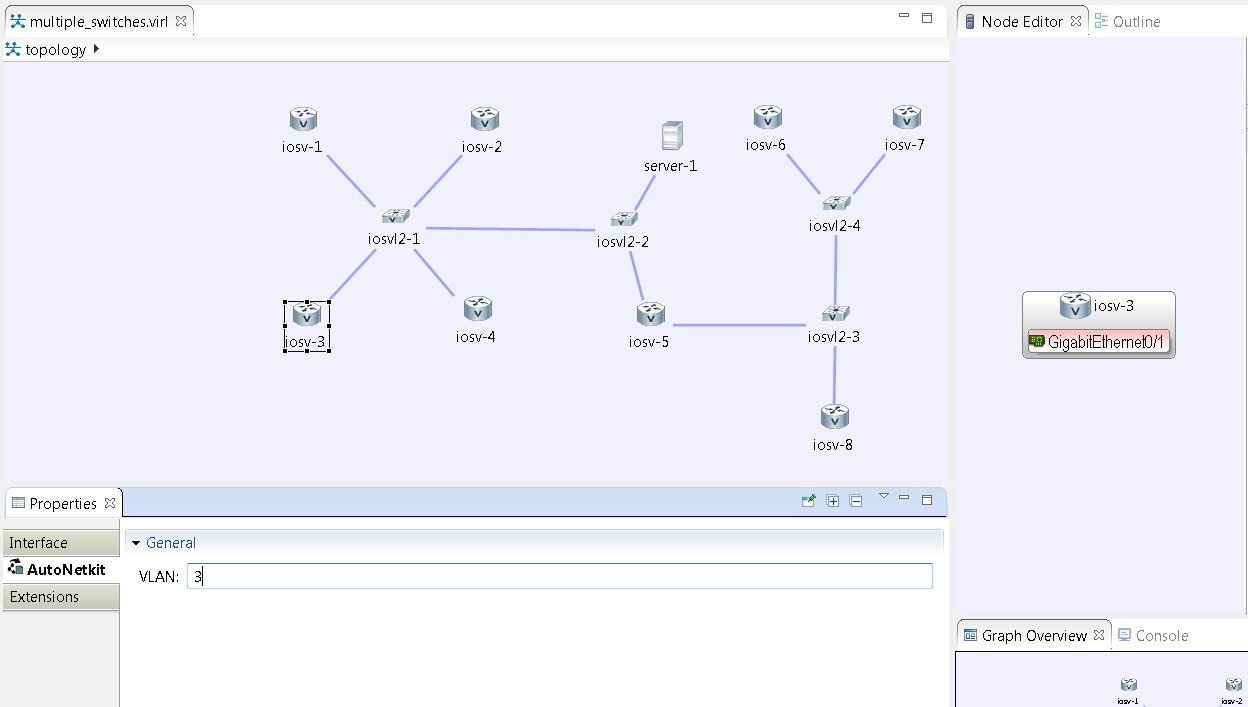
VLANs can be assigned to the interfaces of the end nodes, using the view.
VLANs are set using the VLAN property under the General tab in the AutoNetkit field on the interface. The interface is selected in the Node Editor. The properties are set on the interfaces of the nodes connected to the IOSvL2 image, such as on the IOSv nodes, server node interfaces.
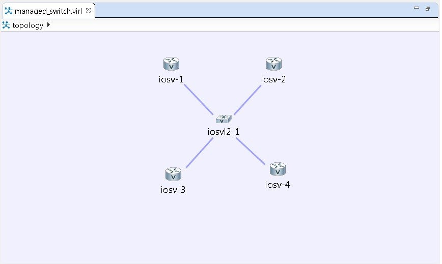
Use a Managed Switch
The Cisco IOSv Layer 2 switch introduces a managed switch to the Cisco Modeling Labs environment.
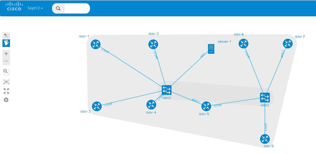
By default, all VLANs are placed in vlan2.
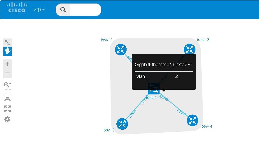
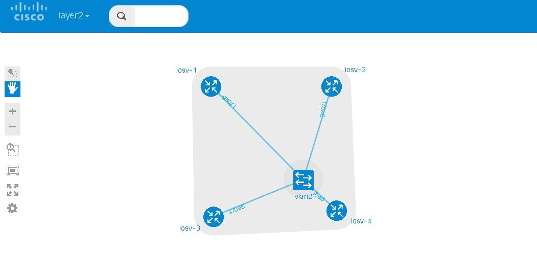
interface GigabitEthernet0/1
 description to iosv-1
 switchport access vlan 2
 switchport mode access
 no shutdown
!
interface GigabitEthernet0/2
 description to iosv-3
 switchport access vlan 2
 switchport mode access
 no shutdown
!
interface GigabitEthernet0/3
 description to iosv-2
 switchport access vlan 2
 switchport mode access
 no shutdown
!
interface GigabitEthernet1/0
 description to iosv-4
 switchport access vlan 2
 switchport mode access
 no shutdown
!
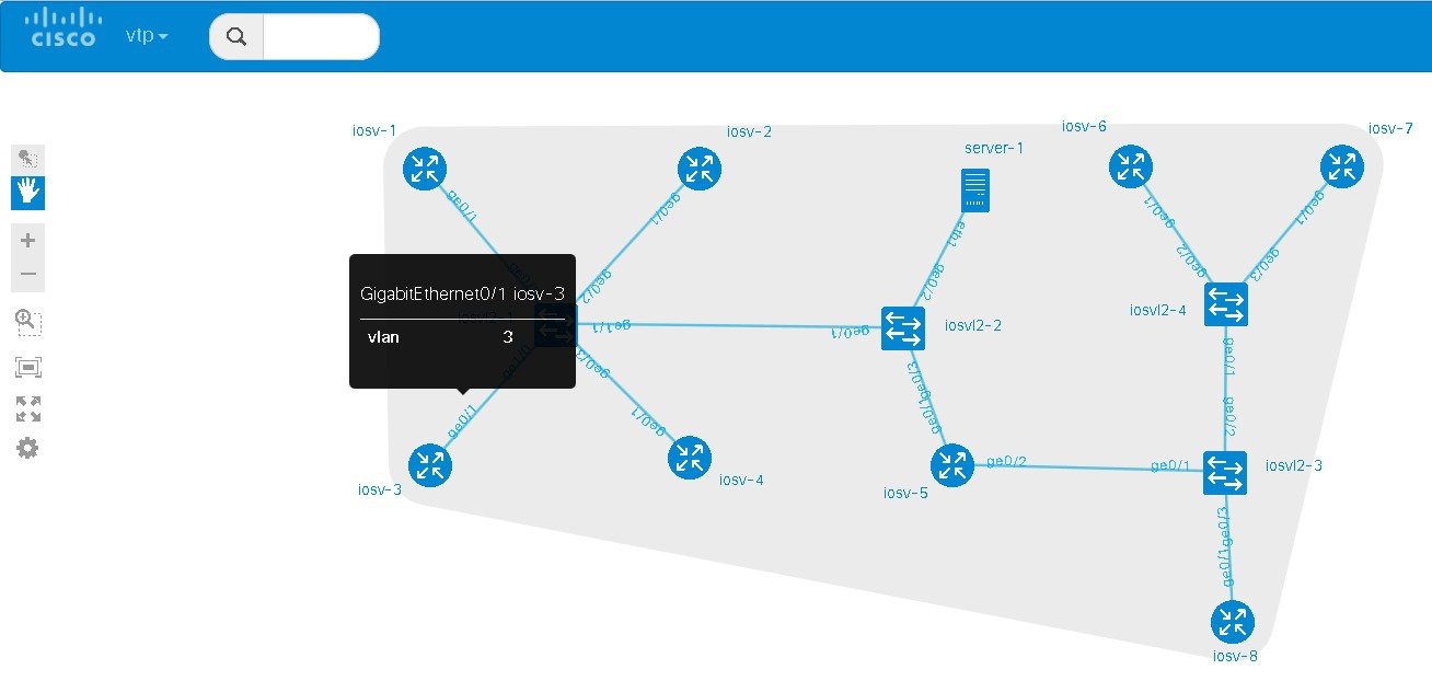
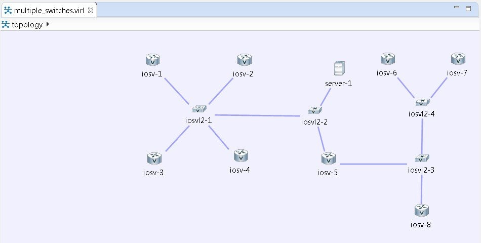
Use Multiple Managed Switches
It is permissible to connect multiple managed switches together. Multiple managed switches connected together form a trunk link between the switches and their appropriate vtp domains.
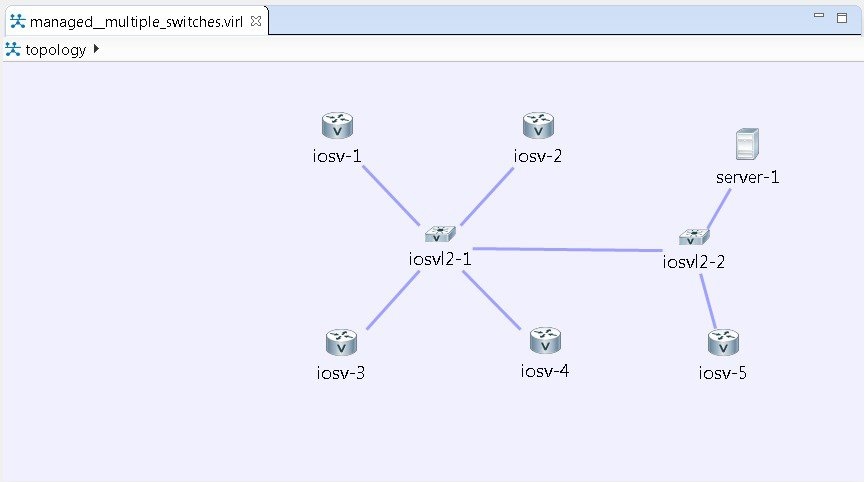
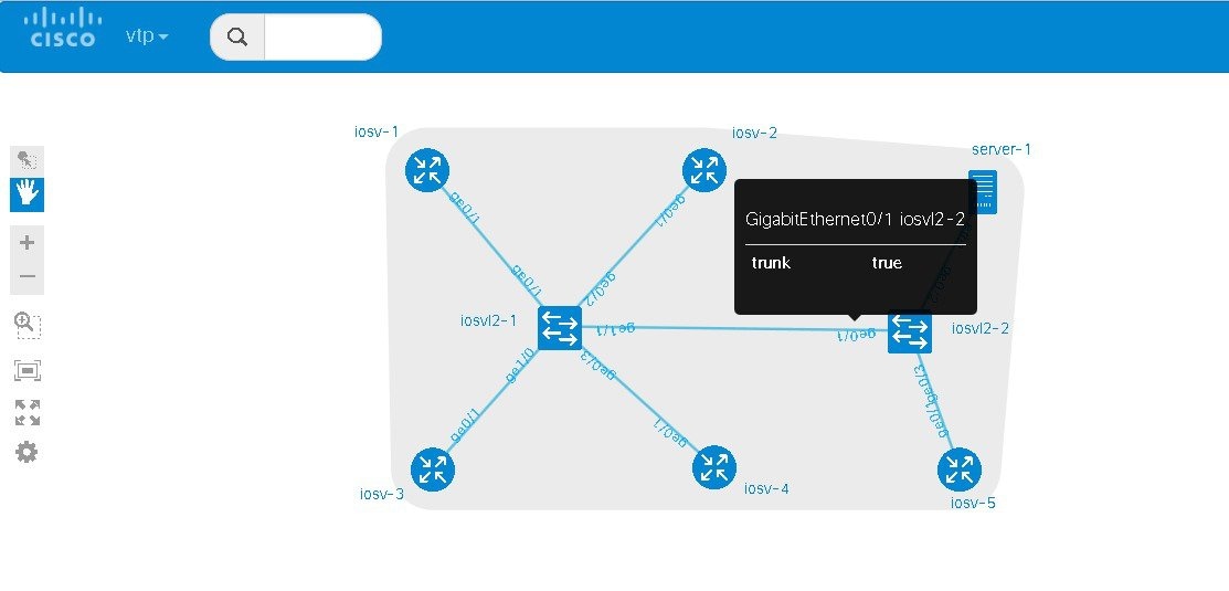
The relevant configurations for iosvl2-1 and iosvl2-2 on the trunk port are shown below.
interface GigabitEthernet0/1
 description to iosv-1
 switchport access vlan 2
 switchport mode access
 no shutdown
!
interface GigabitEthernet0/2
 description to iosv-3
 switchport access vlan 2
 switchport mode access
 no shutdown
!
interface GigabitEthernet0/3
 description to iosv-2
 switchport access vlan 2
 switchport mode access
 no shutdown
!
interface GigabitEthernet1/0
 description to iosv-4
 switchport access vlan 2
 switchport mode access
 no shutdown
!
interface GigabitEthernet1/1
 description to iosvl2-2
 switchport trunk encapsulation dot1q
 switchport mode trunk
 no shutdown
!
interface GigabitEthernet0/1
 description to iosvl2-1
 switchport trunk encapsulation dot1q
 switchport mode trunk
 no shutdown
!
interface GigabitEthernet0/2
 description to server-1
 switchport access vlan 2
 switchport mode access
 no shutdown
!
interface GigabitEthernet0/3
 description to iosv-5
 switchport access vlan 2
 switchport mode access
 no shutdown
!
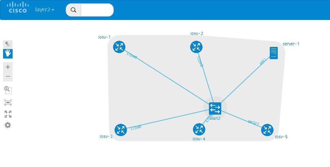
Use Multiple Unconnected Managed Switches
In cases where there are multiple managed switches, only those that are directly connected, either through a point-to-point link or via an unmanaged switch are connected.
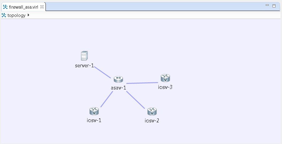
Set Firewall Capabilities
For this release of Cisco Modeling Labs, the Cisco ASAv image is available to purchase separately. The Cisco ASAv image adds firewall capabilities to Cisco Modeling Labs.
The default AutoNetkit configuration puts each interface into security-level 0, adds a nameif, and allows http, SSH, and Telnet access to this nameif.
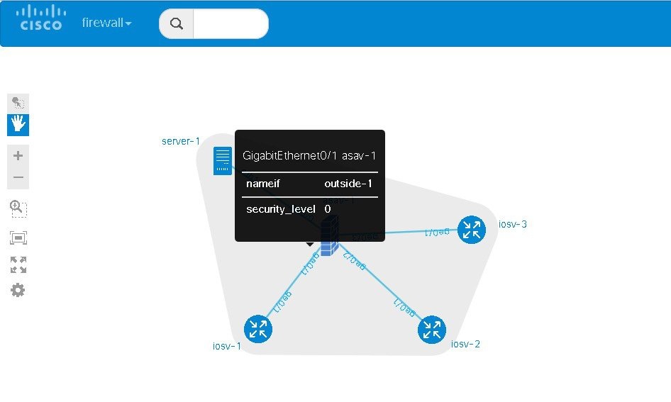
interface GigabitEthernet0/0
 description to server-1
 nameif outside
 security-level 0
 no shutdown
 ip address 10.0.0.5 255.255.255.252
interface GigabitEthernet0/1
 description to iosv-1
 nameif outside-1
 security-level 0
 no shutdown
 ip address 10.0.0.9 255.255.255.252
interface GigabitEthernet0/2
 description to iosv-2
 nameif outside-2
 security-level 0
 no shutdown
 ip address 10.0.0.13 255.255.255.252
interface GigabitEthernet0/3
 description to iosv-3
 nameif outside-3
 security-level 0
 no shutdown
 ip address 10.0.0.17 255.255.255.252
http 0.0.0.0 0.0.0.0 mgmt
ssh 0.0.0.0 0.0.0.0 mgmt
telnet 0.0.0.0 0.0.0.0 mgmt
http 0.0.0.0 0.0.0.0 outside
ssh 0.0.0.0 0.0.0.0 outside
telnet 0.0.0.0 0.0.0.0 outside
http 0.0.0.0 0.0.0.0 outside-1
ssh 0.0.0.0 0.0.0.0 outside-1
telnet 0.0.0.0 0.0.0.0 outside-1
http 0.0.0.0 0.0.0.0 outside-2
ssh 0.0.0.0 0.0.0.0 outside-2
telnet 0.0.0.0 0.0.0.0 outside-2
http 0.0.0.0 0.0.0.0 outside-3
ssh 0.0.0.0 0.0.0.0 outside-3
telnet 0.0.0.0 0.0.0.0 outside-3
Set Security Levels
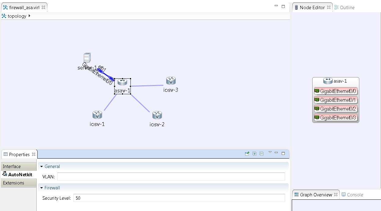
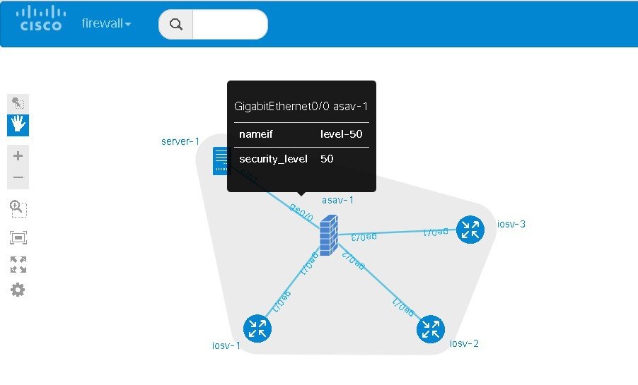
interface GigabitEthernet0/0
 description to server-1
 nameif level-50
 security-level 50
 no shutdown
 ip address 10.0.0.5 255.255.255.252
interface GigabitEthernet0/1
 description to iosv-1
 nameif outside
 security-level 0
 no shutdown
 ip address 10.0.0.9 255.255.255.252
interface GigabitEthernet0/2
 description to iosv-2
 nameif outside-1
 security-level 0
 no shutdown
 ip address 10.0.0.13 255.255.255.252
interface GigabitEthernet0/3
 description to iosv-3
 nameif outside-2
 security-level 0
 no shutdown
 ip address 10.0.0.17 255.255.255.252
http 0.0.0.0 0.0.0.0 level-50
ssh 0.0.0.0 0.0.0.0 level-50
telnet 0.0.0.0 0.0.0.0 level-50
http 0.0.0.0 0.0.0.0 mgmt
ssh 0.0.0.0 0.0.0.0 mgmt
telnet 0.0.0.0 0.0.0.0 mgmt
http 0.0.0.0 0.0.0.0 outside
ssh 0.0.0.0 0.0.0.0 outside
telnet 0.0.0.0 0.0.0.0 outside
http 0.0.0.0 0.0.0.0 outside-1
ssh 0.0.0.0 0.0.0.0 outside-1
telnet 0.0.0.0 0.0.0.0 outside-1
http 0.0.0.0 0.0.0.0 outside-2
ssh 0.0.0.0 0.0.0.0 outside-2
telnet 0.0.0.0 0.0.0.0 outside-2
 Note | AutoNetkit automatically renames the nameif if there are multiple interfaces with the same security level. |
Configure GRE Tunnels
Generic routing encapsulation (GRE) is a simple IP packet encapsulation protocol that is used to transport packets over a network. Information is sent from one network to the other through a GRE tunnel.
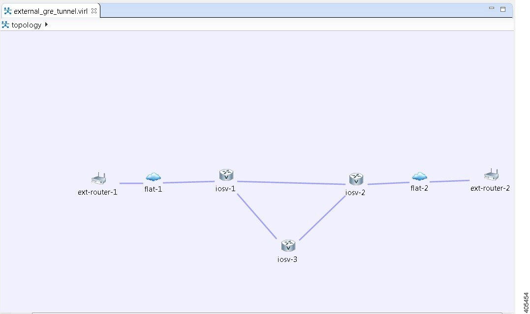
In this example, you set the values on node iosv-1 and node iosv-2 to tell AutoNetkit to create the configuration for a GRE tunnel terminating on the external router node, ext_router_1.
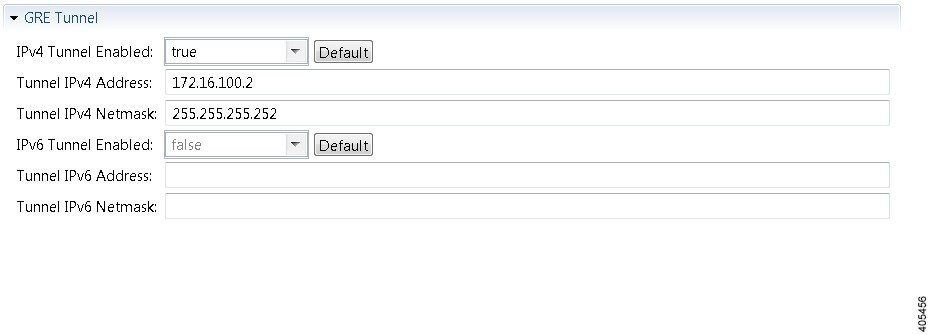
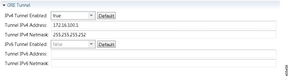
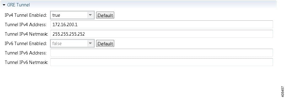
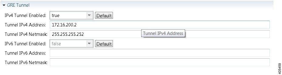
!
interface Tunnel1
  ip address 172.16.100.2 255.255.255.252
  tunnel source GigabitEthernet0/3
  tunnel destination 0.0.0.0
!
The tunnel destination is blank since it needs to be set to the IP address of the far-end device, which you may or may not know in advance. However, you can edit the configuration in the Cisco Modeling Labs client GUI before you start up the simulation. So if you do know the target address, you can add the target IP address in there (tunnel destination x.x.x.x.) Remember that it is not the IP address of the tunnel that goes in here but the IP address of the router/device terminating the GRE tunnel itself. If this is a devices that is on the FLAT network directly, then a 172.16.1.x address would go in here.
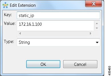
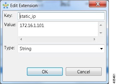
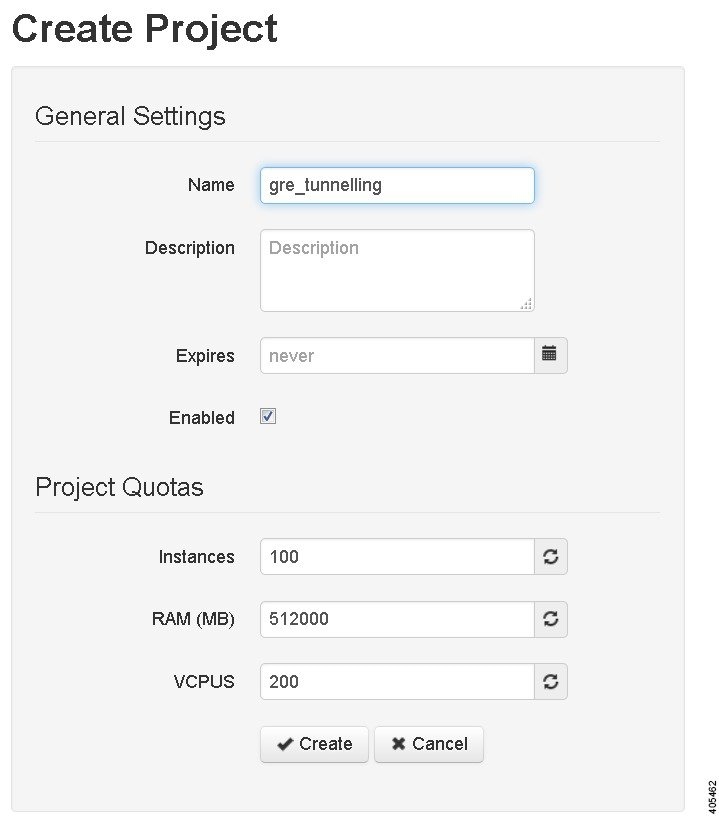
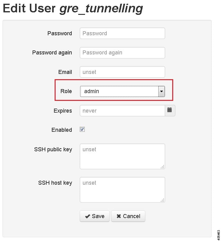
Note | You cannot do this using the standard guest account. The simulation will fail as you are using a system-level resource (the Static IP address), so an account with administrative permissions is required. |
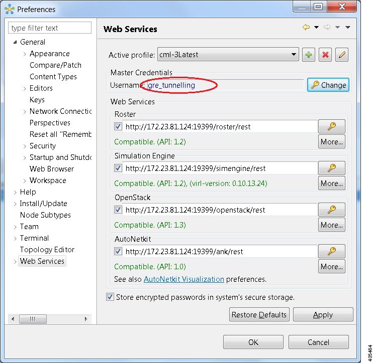
You can now start your simulation.
 Feedback