Reintegrate Cisco ISE with Cisco Catalyst Center
This guide is designed for the following use case:
-
You have an existing Cisco ISE cluster that is integrated with the Catalyst Center, and you want to replace the existing Cisco ISE with a new Cisco ISE.
The objective of the reintegration activity is that Catalyst Center integrates transparently from the existing Cisco ISE to the new Cisco ISE.
 Note |
If you are viewing this guide on cisco.com, click any of its figures to view a full-sized version. |
IP Addresses and Naming Conventions
The following table shows example IP address and naming conventions involved in the migration.
Note |
The round-trip time between XYZ data center and ABC data center is around 20 to 30 ms during peak hours. |
| Technology | Name | IP Address | Location |
|---|---|---|---|
|
Existing Cisco ISE (Primary administration node + Monitoring node + Policy service node+ Device Admin + pxGrid) |
Existing-ISE-1 |
192.0.2.1 |
ABC |
|
Existing Cisco ISE (Secondary administration node + Monitoring node + Policy service node+ Device Admin + pxGrid) |
Existing-ISE-2 |
192.0.2.2 |
ABC |
|
New Cisco ISE (Primary administration node + Monitoring node + Policy service node+ Device Admin + pxGrid) |
New-ISE-1 |
172.16.0.1 |
XYZ |
|
New Cisco ISE (Secondary administration node + Monitoring node + Policy service node+ Device Admin + pxGrid) |
New-ISE-2 |
172.16.0.2 |
XYZ |
|
Catalyst Center-1 |
HQ-SDA-Catalyst-1 |
10.255.255.250 |
ABC |
|
Catalyst Center-2 |
HQ-SDA-Catalyst-2 |
10.255.255.251 |
ABC |
|
Catalyst Center-31 |
HQ-SDA-Catalyst-3 |
10.255.255.252 |
ABC |
|
Catalyst Center VIP |
HQ-SDA-Catalyst |
10.255.255.253 |
ABC |
Existing Setup State
The following figure shows an example of the existing setup.
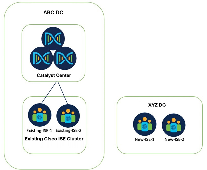
-
Existing-ISE-1 and Existing-ISE-2 are in one cluster and they are responsible for device administration and network authentication.
-
Catalyst Center is integrated with Existing-ISE-1 and Existing-ISE-2 with the following roles:
-
Existing-ISE-1 as primary administration node, primary monitoring node, pxGrid, device admin, and policy service node.
-
Existing-ISE-2 as secondary administration node, secondary monitoring node, pxGrid, device admin, and policy service node.
-
-
New-ISE nodes are currently standalone nodes and are in factory default state. The new ISE cluster is responsible for the same purposes as the existing ISE cluster.
Reintegration Procedures
Reintegration of Cisco ISE with Catalyst Center is explained with the following two migration scenarios:
-
New Cisco ISE nodes can be integrated with the existing Cisco ISE cluster. See, Add New Cisco ISE Nodes to the Existing Cluster.
-
New Cisco ISE nodes cannot be integrated with an existing cluster. See, Change the Cisco ISE Policy Administrator Node in Catalyst Center.
Add New Cisco ISE Nodes to the Existing Cluster
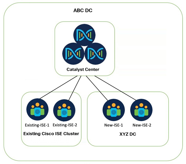
The new Cisco ISE standalone nodes are integrated into the existing Cisco ISE cluster and the ISE personas are distributed as follows:
-
New-ISE-1 [primary administration node + primary monitoring node + pxGrid + policy service node + device admin]
-
New-ISE-2 [secondary administration node + secondary monitoring node + pxGrid + policy service node + device admin]
-
Existing-ISE-1 [pxGrid + policy service node + device admin]
-
Existing-ISE-2 [pxGrid + policy service node + device admin]
Before you begin
Ensure the following:
-
Catalyst Center and the existing Cisco ISE cluster are functioning and SGT synchronization is working.
-
The existing and new Cisco ISE are on the same software version and patch.
-
There is full network connectivity between the existing and the new Cisco ISE nodes.
-
The new ISE nodes have valid certificates.
-
The Smart Registration portal is accessible to mitigate licensing challenges, if any, during the transition.
-
In case you have already formed a new Cisco ISE cluster, you need to break it so that each Cisco ISE node becomes an independent standalone node.
-
Reset the new Cisco ISE applications to the factory default to avoid issues, if any, during the transition.
-
The necessary A and PTR records, pointing to the new Cisco ISE nodes, are added on the DNS servers.
-
Back up the existing Cisco ISE, Catalyst Center, and other device configurations that might be impacted during the transition.
-
Open a proactive TAC case to mitigate Cisco ISE technical and licensing issues, if any.
-
The licenses should be the same for both the existing and new Cisco ISE nodes.
-
The procedure needs to be done in the maintenance window because it may impact device administration and network functionality during the Cisco ISE transition.
-
Keep the same credentials (SSH and GUI) for the existing and new Cisco ISE nodes.
Procedure
|
Step 1 |
Configure the New-ISE and Existing-ISE nodes as follows:
|
||||
|
Step 2 |
Log in to Catalyst Center and verify the following changes:
|
||||
|
Step 3 |
On Cisco ISE, ensure that all network devices are reflected. |
||||
|
Step 4 |
Verify that Catalyst Center and the Cisco ISE cluster are functioning properly. |
||||
|
Step 5 |
Provision the switches and wireless controllers.
You can use the following commands for verification after provisioning:
|
||||
|
Step 6 |
Monitor if everything is fine for a week and then decommission the old Cisco ISE node by deregistering the nodes from the ISE cluster. |
||||
|
Step 7 |
Remove the DNS records pointing to the old Cisco ISE nodes. |
Change the Cisco ISE Policy Administrator Node in Catalyst Center
This procedure explains how to change the Cisco ISE Policy Administration Node (PAN) in Catalyst Center.
Use this procedure to configure new Cisco ISE nodes in Catalyst Center when the new Cisco ISE nodes cannot be integrated with an existing cluster.
Note |
This procedure cannot be used if SGTs are mapped to IP pool in the virtual network on Catalyst Center, or if there are any edge nodes with static SGT binding on any port, or both. |
Before you begin
Ensure the following:
-
There is no need of network connectivity between the new and existing Cisco ISE clusters. But ensure that the Cisco ISE clusters are reachable from Catalyst Center.
-
There is no need for the new Cisco ISE nodes to be independent. You can create a cluster with the new Cisco ISE nodes with the required certificates and personas. The new Cisco ISE node does not need to be of the same version as the existing Cisco ISE node.
-
Generate new certificates for the new Cisco ISE nodes.
-
Match the new Cisco ISE personas with the existing Cisco ISE deployment.
-
Keep the same licenses for the new Cisco ISE and the existing Cisco ISE.
-
Back up the automation data of Catalyst Center and the operational and configuration data of your existing Cisco ISE. Also, back up other device configurations, as required.
For more information, see "Backup and Restore" in the Cisco Catalyst Center Administrator Guide.
Procedure
|
Step 1 |
If you use AAA for Catalyst Center authentication, change to local authentication (to prevent a possible GUI lockout). |
||||
|
Step 2 |
In the window, create one entry of type AAA that points to an unused IP address. |
||||
|
Step 3 |
In the window, change the Cisco ISE servers under both the client/endpoint and the network to point to the unused IP address that you created in the preceding step. |
||||
|
Step 4 |
In the window, click the Wireless tab and point any AAA SSIDs to the unused IP address. Repeat this step at child level if you've configured any AAA override. |
||||
|
Step 5 |
Confirm that Catalyst Center can reach both the new PAN and SAN. Delete the old Cisco ISE server from the Catalyst Center, and integrate the new Cisco ISE server. Then confirm that the new Cisco ISE node appears as active in the Catalyst Center GUI. |
||||
|
Step 6 |
In the window, under the client/endpoint or network or both, change the Cisco ISE servers to point to the new Cisco ISE servers. |
||||
|
Step 7 |
In the window, click the Wireless tab and point any AAA SSIDs to the new Cisco ISE servers. Repeat this step at child level if you've configured any AAA override. |
||||
|
Step 8 |
In the Group-Based Access Control (GBAC) window, start the Cisco ISE migration and make sure it completes. Log in to the new Cisco ISE node and verify whether the SGTs configured on Catalyst Center are populated in the new Cisco ISE node. Create a new SGT in Catalyst Center and check if it's pushed to the Cisco ISE node. |
||||
|
Step 9 |
Provision the network devices (switches and wireless controllers) from the inventory to reconfigure them with the new AAA servers.
You can use the following commands for verification after provisioning:
|
||||
|
Step 10 |
Reconfigure Cisco ISE for external authentication, if required.
|
 Feedback