Validated Profile: Enterprise and Government (SD-Access) Vertical
Available Languages
Bias-Free Language
The documentation set for this product strives to use bias-free language. For the purposes of this documentation set, bias-free is defined as language that does not imply discrimination based on age, disability, gender, racial identity, ethnic identity, sexual orientation, socioeconomic status, and intersectionality. Exceptions may be present in the documentation due to language that is hardcoded in the user interfaces of the product software, language used based on RFP documentation, or language that is used by a referenced third-party product. Learn more about how Cisco is using Inclusive Language.
- US/Canada 800-553-2447
- Worldwide Support Phone Numbers
- All Tools
 Feedback
 Feedback
Cisco Software-Defined Access (SD-Access) is the evolution from traditional campus LAN designs to networks that directly implement the intent of an organization. SD-Access is enabled with an application package that runs as part of the Catalyst Center software for designing, provisioning, applying policy, and facilitating the creation of an intelligent campus wired and wireless network with assurance.
Fabric technology, an integral part of SD-Access, enables wired and wireless campus networks with programmable overlays and easy-to-deploy network virtualization, permitting a physical network to host one or more logical networks to meet the design intent.
The enterprise market segment can be divided into different verticals: government, financial, health, and retail. This document covers the government vertical.
An enterprise and government environment typically contains a large number of devices and endpoints in the main fabric site. The solution focuses on validating all the fabric automation use cases and assurance at scale. The key components are:
● End-to-end solution deployment with the maximum fabric scale.
● Multiple Catalyst Center instances with a common Cisco Identity Service Engine (Cisco ISE) cluster.
A large government deployment requires more than one Catalyst Center instance. The Multi-Catalyst Center feature provides the functionality for multiple Catalyst Centers to integrate with the same Cisco ISE cluster. All the virtual networks, security groups, access contracts, and security policies are created and shared among Catalyst Centers. The operations are performed through the primary node (Author node) and pushed to Cisco ISE and other Catalyst Center.
● Migration to IPv6.
Devices increasingly run on IPv6, while network infrastructures are likely to continue on IPv4. Catalyst Center provides a seamless workflow for IPv6 migration.
● Wireless migration (from deploying the wireless OTT to the migration of fabric wireless).
Some enterprise deployments choose to migrate to an SD-Access network in phases. The wired network is migrated first; the traditional wireless network is carried on top of the fabric wired network. This type of network is known as wireless over the top of fabric, or wireless OTT. The next phase migrates and enables the fabric wireless network.
● Cisco Catalyst Assurance.
Assurance provides visibility to the actual experiences of users and applications across the end-to-end network.
Hardware and software specifications
The solution is validated with the hardware and software listed in this table.
| Role |
Hardware platform |
Software release |
|
| Catalyst Center Controller |
DN3-HW-APL-XL |
2.3.7.9 |
2.3.7.10 |
| Identity Management, RADIUS Server |
ISE-VM-K9 |
3.3 Patch 4 |
3.4 Patch 3 |
| Cisco SD-Access Fabric Border |
C9500-24Y4C |
17.9.6a, 17.12.5, 17.15.3 |
17.12.6, 17.15.4d, 17.18.3 |
| Cisco SD-Access Fabric Edge |
C9500-40X, C9404R, C9300 |
17.9.6a, 17.12.5, 17.15.3 |
17.12.6, 17.15.4d, 17.18.3 |
| Cisco SD-Access Transit Node |
C9500-24Y4C |
17.9.6a, 17.12.5, 17.15.3 |
17.12.6, 17.15.4d, 17.18.3 |
| Cisco Wireless Controller |
C9800-80-K9
AIR-CT-8540 |
17.9.6, 17.12.5
8.10.196.0 |
17.12.6, 17.15.4d, 17.18.3
8.10.196.0 |
| Cisco Access Point |
C9115AX, C9120AX, C9130AX
AIR-AP-3800, AIR-AP-4800 |
17.9.6, 17.12.5
8.10.196.0 |
17.12.6, 17.15.4d, 17.18.3
8.10.196.0 |
Solution use case scenarios
This validated solution supports these Automation and Assurance use cases:
Automation use case
● Deploy the large government fabric site
● Fabric device onboarding with LAN automation
● Virtual network and IP segment addition
● IP and TCP transit
● Multicast enablement
● Multi-Catalyst Center integration with the same Cisco ISE cluster
● Virtual network, security group tags, access contracts, and secure policy creation
● Role change (promotion of author node) among Catalyst Centers
● Policy enforcement and Change of Authorization (COA)
● Wireless OTT deployment and migration to the fabric wireless
● Migration from an IPv4-only network to a dual-stack network
● Wired and wireless fabric device image upgrade validation
● Site-level device image upgrade, including wired and wireless devices
● Catalyst Center three-node cluster upgrade validation
● Catalyst Center upgrade from 2.3.5.6 to 2.3.7.7
● Network and service failover/redundancy validation
● Catalyst Center high availability
● ISE PAN, PSN, and pxGrid service failover
● ISE unreachable with critical VLAN
● Border SVL and access switch stack failover
● Fabric device RMA workflow and AP refresh workflow
● Fabric device and faulty AP RMA
● Entire AP replacement from Wav2 AP to 11ax AP
● Fabric Scale and Performance
Assurance use case
● Dual-stack fabric client onboarding
● Wired and wireless dual-stack client onboarding
● Client dashboard shows the list of onboarded client devices with their correct health scores and all other expected information
● Network device onboarding
● Network dashboard shows the list of onboarded network devices with their correct health scores and all other expected information
● Assurance issue reporting
● Link down issue generation for network devices
● AP down issue generation
● Stack member down
● Client health drill down
● Assurance charts in the Client Health page
● Assurance charts in the Client 360 page
● Network health drill down
● Assurance charts in the Network Health page
● Assurance charts in the Device 360 page
● Fabric Assurance
● Fabric health score and Assurance charts in the Fabric Health page
● Assurance with scale
● Assurance charts with 300,000 concurrent endpoints and 750,000 transient endpoints
● Longevity/soak test
Solution environment
Topology
The topology illustrates the solution environment for large enterprises and government deployments.
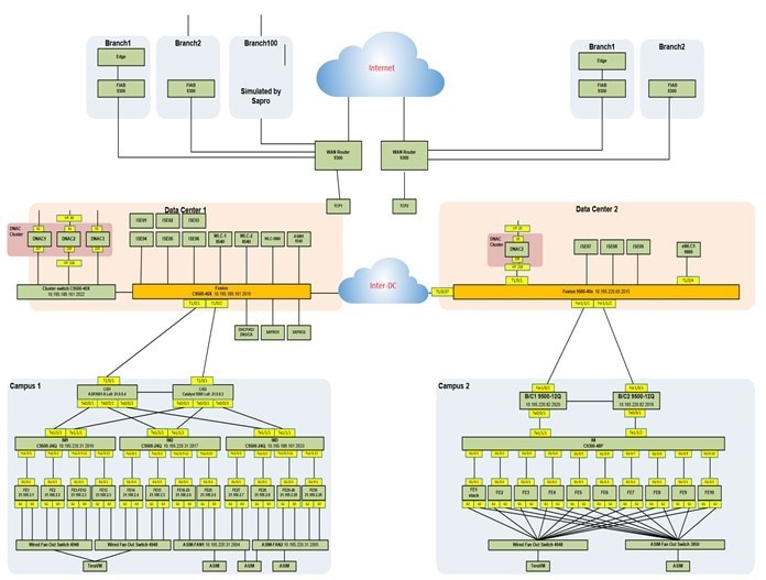
Controller integration:
● Data Center 1: One three-node, 112-core Catalyst Center cluster, two ISE PAN/MNTs, and three PSN nodes.
● Data Center 2: One single-node, 112-core Catalyst Center with three ISE PSN nodes.
● The shared service contains DNS, DHCP, AD, NTP, HTTP, TFTP, and backup servers. WLCs also reside in the shared service.
Two large fabric campus sites:
● Campus 1: Dual-fabric borders/CP, 1000 fabric edges, 1000 IP segments.
● Campus 2: Border with SVL, 1000 fabric edges, 600 IP segments.
● Branches: FIAB in branch with communication to the campus via transit CP nodes (one for each campus).
● Both campuses contain numerous simulated fabric nodes, APs, and simulated wired/wireless endpoints.
Scale
Solution test verified the scale numbers listed in this table. For the hardware capacity, see the Cisco Catalyst Center Data Sheet.
| Attribute |
Value |
Notes |
| Catalyst Center clusters |
4 |
One three-node cluster and one single-node, 112-core appliance |
| Cisco ISE clusters |
8 |
Two x PAN/MNT, six PSNs (including two pxGrid) |
| Devices in inventory |
10,000 |
Routers, switches, and wireless controllers |
| Devices per fabric |
1054 |
Two border/control plane + 50 switches + 950 simulated switches Two fabric borders/control planes + 50 fabric edge nodes + 1000 simulated switches + two wireless controllers |
| Static host ports |
700,000 |
700,000 physical interfaces |
| Site elements in the network hierarchy |
10,000 |
Areas, buildings, and floors |
| VNs in the fabric |
256 |
─ |
| IP pools in a fabric site |
1000 |
1000 IP segments |
| Wireless controllers in a fabric site |
2 |
One C9800-80 One AIR-CT-8540 |
| SSIDs |
10 |
─ |
| APs in inventory |
25,000 |
─ |
| APs in a fabric site |
6000 |
─ |
| Endpoints |
300,000 |
200,000 wired 100,000 wireless |
| Catalyst Centers in a multi-Catalyst Center environment |
2 |
─ |
| SGTs |
400 |
─ |
| ACA policies |
25,000 |
─ |
| Operation |
Performance measurement (minutes) |
| Add an IP segment |
35 |
| Delete an IP segment |
26 |
| Add a fabric edge node |
28 |
| Remove a fabric edge node |
15 |
| Add an external border/control plane |
48 |
| Remove an external border/control plane |
37 |
| Enable multicast in VN |
50 |
| Disable multicast in VN |
40 |
| Enable IPv6 in one IPv4 segment |
35 |
| Provision 100 APs |
4 |
| Distribute image to 50 switches via SWIM |
21 |
| Activate image on 50 switches via SWIM |
40 |
| Change the multi-Catalyst Center role (includes synchronization time) |
33 (4000 SGTs) |
| Back up Catalyst Center |
Fusion data: 22 (46 GB) |
Best practices and recommendations
This section describes the technical notes useful for deploying the solution.
Wireless OTT migration
Wireless OTT is the traditional wireless carried on top of the SD-Access fabric. This mode is important as a migration step for customers who decide to implement SD-Access first on the wired network and then plan the wireless integration. When migrating an OTT deployment to an SD-Access wireless network, follow this procedure to retain the same SSID names for the wireless network.
Procedure 1. To retain the same SSID names for the wireless network during migration:
Step 1. On the Fabric page, add the wireless controller to the fabric site.
Step 2. Retain the same SSIDs in the fabric network as the OTT. Create a new network profile and add the same SSIDs to the profile with fabric enabled.
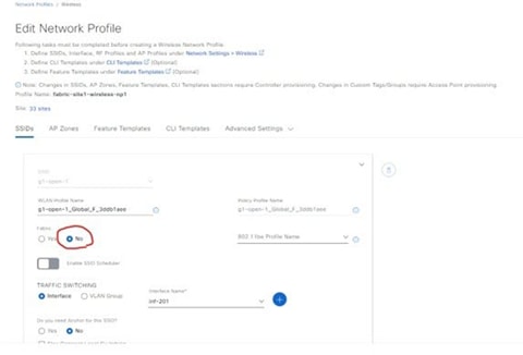
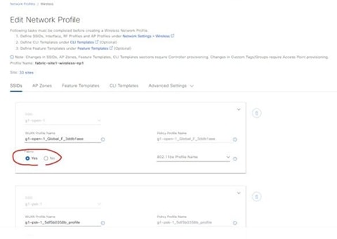
Step 3. Assign the floors to the new network profile.
Step 4. Reprovision the wireless controller with the new network profile. This removes the old nonfabric SSIDs and generates new fabric SSIDs.
Step 5. On the Host Onboarding > Wireless SSID page, assign wireless pools to the SSIDs in the fabric. This enables the fabric SSIDs in the wireless controller.
Step 6. Reprovision the APs for the assigned floors. APs reboot and start to broadcast the fabric SSIDs. Access tunnels are created for each fabric AP in the fabric edge nodes.
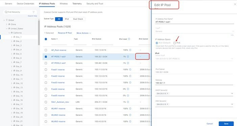
IPv6 migration (dual-stack enablement)
Many deployments have IPv4-only segments. This procedure is recommended for IPv6.
Procedure 1. To migrate to a dual-stack environment that supports IPv6:
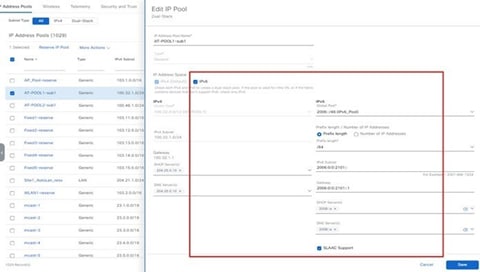
Step 1. Create an IPv6 global pool.
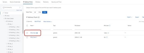
Step 2. Select the IPv4 pool and edit it with the IPv6 pool.
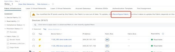
Step 3. After the pool information is saved, Catalyst Center adds an alert on the Fabric page. At the prompt, reconfigure the fabric.
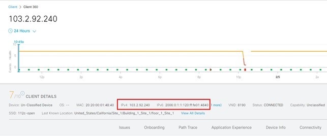
Step 4. After the provisioning completes, onboard the hosts and endpoints. The onboarding hosts get both IPv4 and IPv6 addresses.
Step 5. On the Assurance page, view the dual addresses.
Multi-Catalyst Center deployment
Catalyst Center systems cannot scale to more than 25,000 to 100,000 endpoints (25,000 for 44-core appliances, 40,000 for 56-core appliances, and 100,000 for 112-core appliances). Cisco ISE can scale to 2,000,000 endpoints. Before release 1.3.3.x, only one Catalyst Center system could integrate with one Cisco ISE system. Now, large Cisco ISE deployments can benefit by integrating multiple Catalyst Center clusters with a single Cisco ISE. This feature along with the Access Control Application in Catalyst Center allows you to integrate up to four Catalyst Center clusters with a single Cisco ISE system.
Information to understand about a multi-Catalyst Center deployment:
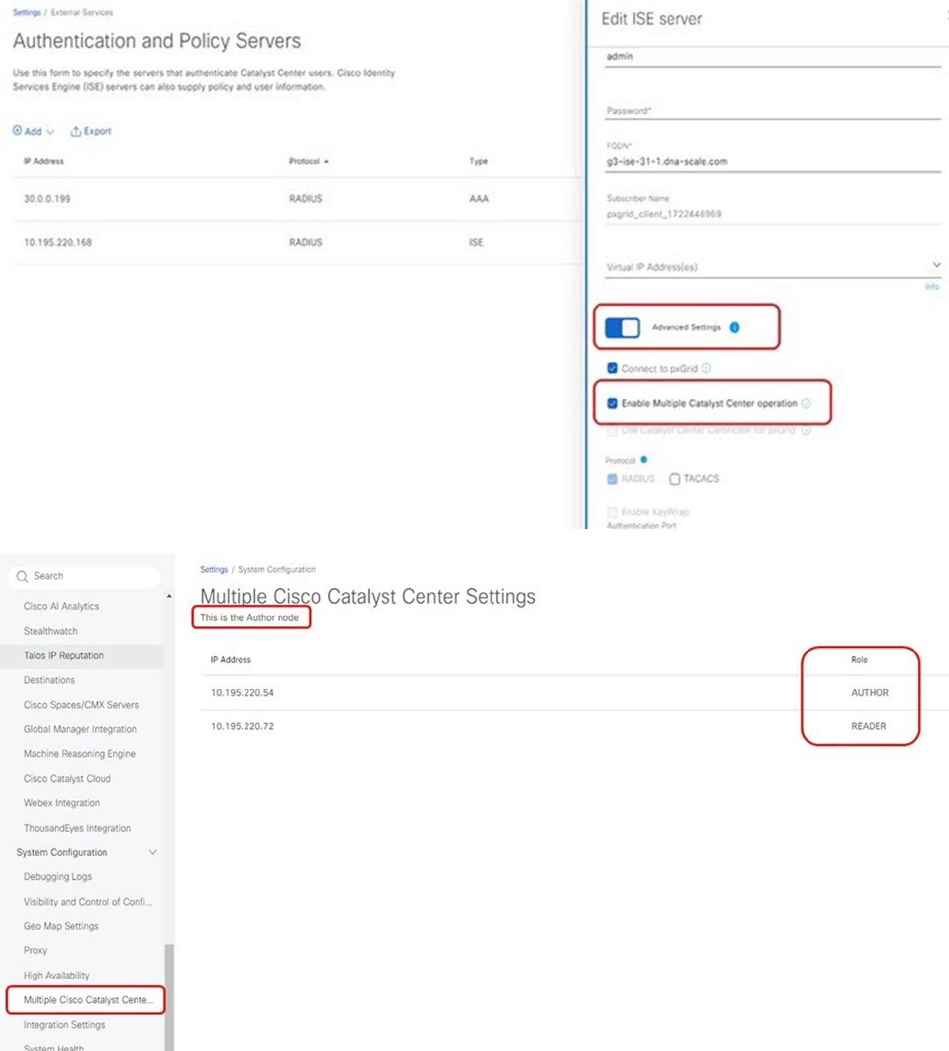
● The feature is built-in for Catalyst Center 2.3.7.x and later integrated with Cisco ISE 3.2 and later. You only need to enable the feature on the Settings page. Otherwise, you must install the multi-dnac-enablement application package to enable the feature.
● In a multi-Catalyst Center deployment, all Catalyst Center clusters must be the same release to integrate with the same Cisco ISE cluster. Cross-release of Catalyst Center is not supported in a multi-Catalyst Center deployment.
● The dependency package for the multi-dnac-enablement package is the Access Control Application package. You must install the ACA package before installing the multi-dnac-enablement package.
● In a deployment with one Cisco ISE system and multiple Catalyst Center clusters, only the Author node can manage SDA policy objects. The first Catalyst Center cluster that you integrate with Cisco ISE assumes the Author node role. The Author node is the single point of administration for virtual networks, scalable groups, access contracts, policies, and scalable group-virtual network associations. The Reader node has a read-only view of virtual networks, scalable groups, and the virtual network associations between scalable groups. The Reader node cannot display access contracts or policies. The Reader node has a link to cross-launch to the Author node.
● When the Cisco ISE system integration is complete, you can confirm the role status as an Author node and a Reader node on the System > Settings > Multiple Cisco Catalyst Center Settings page.
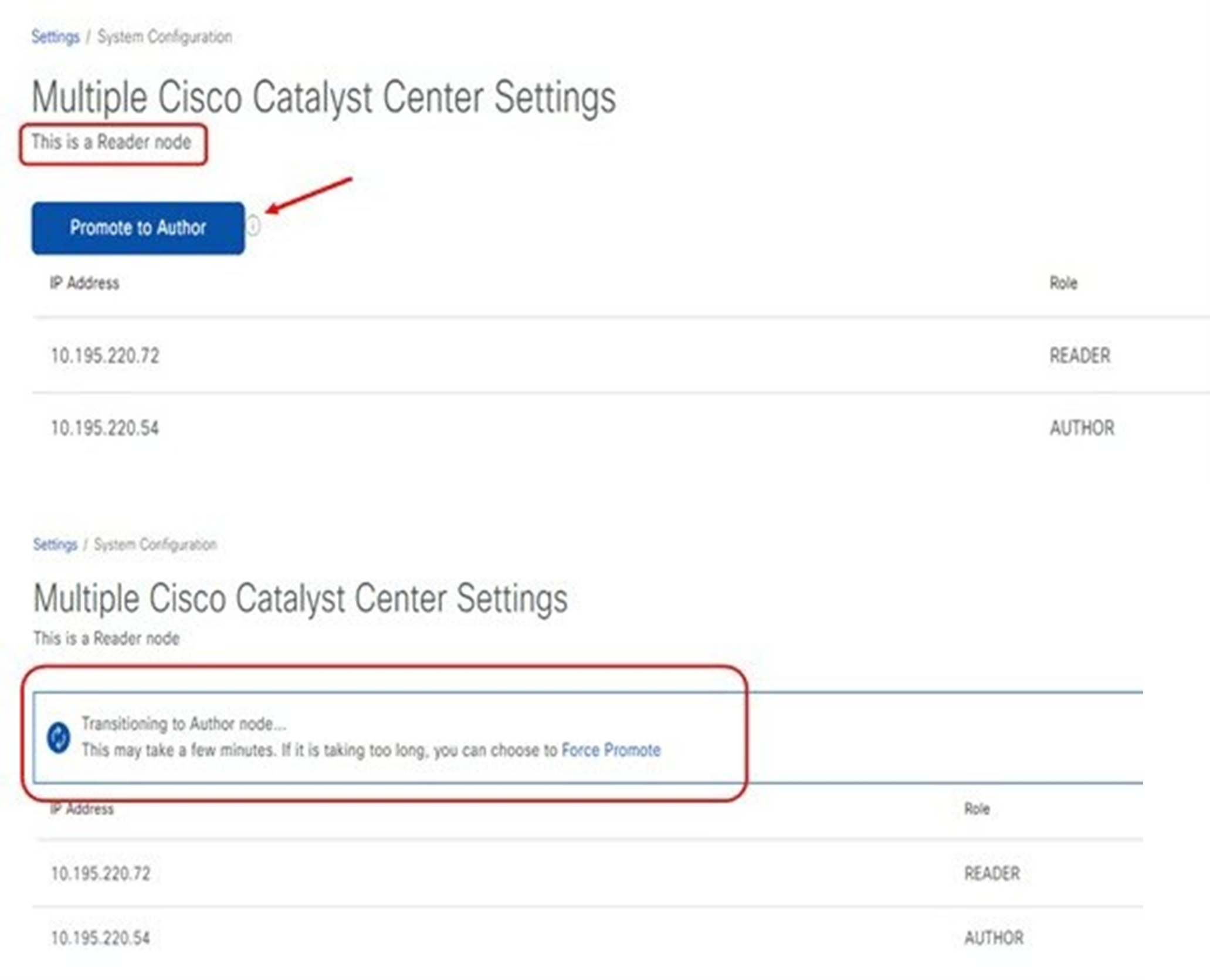
● The Reader node can be promoted to the Author node to replace the current Author node. After the promotion, the new Author node must perform a resync of the Cisco ISE database for the policy data. If the cluster has a large number of SGTs, the resync time increases. After the resync is complete, the new Author node can be used to manage all the access control policies for the entire deployment.
Assurance
The Assurance Summary dashboard from the Catalyst Center home page displays the overall health status of the network.
Procedure 1. To view the Assurance Summary from Catalyst Center Home page:
● From this dashboard, drill down to the Assurance Overall page or the Assurance Issues page.
Procedure 2. To use the Assurance Overall page:
Step 1. From the main menu, choose Assurance > Health to view aggregate health information for network devices and clients.
The default view shows data for the last 7 days.
Step 2. Adjust the display to the last 3 hours or 24 hours.
Procedure 3. To view the Network Health page:
● From the main menu, choose Assurance > Health. Click the Network.
The Network Health page has sections for:
- Network Device Reachability,
- Top N APs by High Interference,
- Total APs Up/Down,
- Top N APs by Client Count,
- PoE Operational State Distribution,
- PoE Powered Device Distribution,
- and PoE Insights.
Procedure 4. To view the Client Health page:
● From the main menu, choose Assurance > Health. Click the Client tab.
The Client Health page has sections for Wireless Clients and Wired Clients.
The Network Health page has panels for:
- Client Onboarding Times,
- Connectivity RSSI,
- Connectivity SNR,
- Client Roaming Times,
- Client Count per SSID,
- and Connectivity Physical Link.
Procedure 5. To view the Device 360 page:
● From the main menu, choose Provision > Inventory. Click a device and then click View 360.
Procedure 6. To view the Client 360 page:
● From the main menu, choose Assurance > Health. Click the Client tab.
The Client 360 page displays a 360° view of the client device.
Procedure 7. Understand the analytics provided for the fabric overlay:
All fabric overlay charts are available in the Device 360 and Client 360 pages.
● Fabric reachability: Connectivity checks between all fabric nodes.
● Fabric device: Fabric nodes mapping entries, protocols, and performance.
● Fabric clients: Client onboarding and shared services (DHCP, DNS, AAA, RADIUS).
Troubleshooting Assurance
● If multiple Assurance dashboards show no data, use the magctl appstack status command to check that all Assurance services are running. Use the Flink tool to check that all Assurance pipelines are running.
● If the Network Health page intermittently shows no data, check the Network-health processor or Graph-Writer LAG in Grafana.
● If wired clients don’t show the correct details, check for any Wired Pipeline LAG in Grafana.
Catalyst Center air gap upgrade
Some government agencies have strict security requirements that restrict the deployment of management solutions in a cloud environment. Catalyst Center supports offline software updates, allowing Catalyst Center appliances deployed in secure, air-gapped networks to be updated to the latest Catalyst Center software and application versions, without having to access the Cisco Connected Cloud. To upgrade your Catalyst Center appliance in an air-gapped environment, see the "2.3.5.x or 2.3.6.x to 2.3.7.x" chapter in the Cisco Catalyst Center Standard Air Gap Deployment Guide.