Validated Profile: Healthcare (SD-Access) Vertical
Available Languages
Bias-Free Language
The documentation set for this product strives to use bias-free language. For the purposes of this documentation set, bias-free is defined as language that does not imply discrimination based on age, disability, gender, racial identity, ethnic identity, sexual orientation, socioeconomic status, and intersectionality. Exceptions may be present in the documentation due to language that is hardcoded in the user interfaces of the product software, language used based on RFP documentation, or language that is used by a referenced third-party product. Learn more about how Cisco is using Inclusive Language.
- US/Canada 800-553-2447
- Worldwide Support Phone Numbers
- All Tools
 Feedback
 Feedback
This guide describes a Cisco-validated profile (CVP) for a Healthcare production network that uses Cisco Catalyst Center and Cisco SD-Access. This guide helps deployment engineers make the best decisions for their network during deployment and configuration.
Note: For the Healthcare Non-Fabric Cisco Validated Profile, see Validated Profile: Healthcare (Non-Fabric Vertical).
Target audience
The audience for this guide is IT and operational technology (OT) professionals who deploy or manage Healthcare production networks. This guide serves as a validation reference for vendors, partners, system implementers, customers, and service providers involved in designing, deploying, or operating production systems.
Solution overview
The purpose of this document is to provide guidance for a typical healthcare deployment profile using Catalyst Center and Cisco SD-Access and serve as a validation reference. Significant changes have been taking place in the healthcare industry, such as exponential growth in telehealth and virtual care, the sudden increases in remote workforces, increased security concerns, fast-evolving primary care models, shifts in care delivery sites, and the prioritization of worker safety and wellness. The section topics describe the key considerations for a large, evolving healthcare network that needs to meet today's healthcare requirements.
Service and network resiliency
The healthcare system requires strict network- and service-level resiliency, as it cannot afford to have long downtimes. Network-level resiliency can be achieved with a robust fabric network design that includes dual fabric borders nodes, dual fabric control plane nodes, dual anchor borders and control plane nodes, dual wireless controllers, fabric switches with either hardware stacking or StackWise Virtual, dual multicast rendezvous-points (RP), and dual fabric transit control plane nodes (where applicable). Service-level resiliency is achieved by deploying these clusters:
● A Catalyst Center three-node cluster.
● A distributed Cisco Identity Services Engine (ISE) cluster with multiple Policy Administration Nodes (PAN), Monitoring Nodes (MNT), as well as active and standby Platform Exchange Grid (pxGrid) and Policy Service Nodes (PSN).
Network expansion
A healthcare network typically comprises of several large-scale campus sites and many small-scale branch or clinic sites. For a major health service provider, its clinical sites can number in the hundreds or even thousands. The surge in demand for telehealth and virtual care is matched by a corresponding rise in demand for the dynamic deployment of new clinic sites and the expansion of existing campus and clinic sites.
Catalyst Center provides ample support for flexible site additions and site expansion. The LAN Automation feature provides a zero-touch plug-and-play workflow to discover new devices and automate the creation of the underlying Layer 3 unicast and multicast network that connects to the existing network in a multitier fashion. Once in inventory, these newly discovered devices are ready to be provisioned with AAA configurations and added into a fabric with a fabric role. Catalyst Center also offers another unique zero-touch plug-and-play workflow that brings extended node devices into the Cisco SD-Access fabric site. The end-to-end workflow starts from discovery and continues through to IP address assignment, base provisioning, and fabric provisioning. Cisco SD-Access Extended Nodes increase the reach of a healthcare network by providing connectivity to uncarpeted spaces such as hospital parking lots or warehouses. They also greatly increase port density without the need to add additional fabric edge switches. Catalyst Center has the option to configure border nodes at a central location in order to provide internet access for the new sites through Cisco SD-Access Transit. When this option is enabled, all traffic from local sites that's destined for the internet will be forwarded to the local site border, then to the central campus site border. The traffic then exits the fabric domain. This not only provides an option to enforce security policies in a centralized location, but it also offers flexibility and reduces operational overhead for new site deployment, especially in scaled environments.
Network services
Anchored services
The design of a large hospital network is very similar to that of most large campus networks, with a few differences. The main purpose of a hospital is to provide services to patients and guests. At any time, the hospital is likely to have extensive guest services across all of its sites. Securely and reliably handling all of the wireless guests across multiple sites is an operational challenge. Another difference is that hospital networks contain massive amounts of medical devices such as monitors, pumps, medical-grade stations, servers, and imaging equipment. These devices could be located in different locations but may need to be in the same subnet for L2 adjacency and managed in a unified manner from both the control and data plane points of view. Typically, any endpoint that is bound to its individual fabric site receives IP addresses from the local site address pool, and all traffic is directed through local site borders. This adds complexity for address management and policy enforcement for each managed site.
Catalyst Center provides the Multisite Remote Border solution, which can simplify the extension of a subnet between sites. This solution offers a simple and consistent anchored service for a particular Virtual Network (VN), the anchored VN, for both wired and wireless endpoints across sites. For anchored services, traffic for all of the endpoints that belong to the anchored VN at each dispersed site will be aggregated and tunneled back to a central location (the Anchor Border at the Anchor site) over Virtual Extensible LAN (VXLAN). This allows a single subnet to be deployed for clients across different sites. With this simplified and centralized subnet structure, the Multisite Remote Border solution facilitates service deployment and provides a clean and secure segmentation for anchored traffic in a multisite healthcare environment.
Multicast services
Most healthcare networks need to accommodate a large number and variety of devices that service medical staff and patients, such as medical-grade computers, monitors, security cameras, and image analysis equipment. Data generated by these devices needs to be stored both locally and on remote hospital medical servers. This data must be accessible at any moment and in real time. Different types of servers—electronic medical records servers, medical image processing servers, medical billing servers—are often located in a dedicated medical server room in the main campus or main headquarter site of large healthcare organizations or medical research centers. These servers distribute mission-critical and time-sensitive data to multiple endpoints across distributed campus sites. Enabling multicast will offer optimal bandwidth and CPU utilization for data communications between medical servers and endpoint devices.
Catalyst Center provides a rich multicast solution that offers both PIM Any-Source Multicast (PIM-ASM) and PIM Source-Specific Multicast (PIM-SSM) in both the overlay and the underlay. This solution offers two different transport methods for multicast forwarding, tailored for different customer network design at a per-VN basis. The first method is head-end replication (that is, ingress replication), which offers a clean, overlay-only multicast forwarding solution (as it does not require multicast in the underlay network). The second method is native multicast, which offers the most scalable bandwidth and CPU efficiency wherever multicast replication is done throughout the underlay network.
Silent medical device handling
Every day, thousands of medical devices connect to a healthcare network. Among these devices, some endpoints fall into the silent host category. These endpoints generally require the receipt of an Address Resolution Protocol (ARP) broadcast packet to come out of silence. Catalyst Center provides the Layer 2 flooding capability to support these silent hosts. Layer 2 flooding enables the flooding of broadcast, link-local multicast, and ARP traffic for a given overlay subnet. It maps the overlay subnet to a dedicated multicast group in the underlay, encapsulates the targeted traffic in a fabric VXLAN, and sends the traffic to the destination's underlay multicast group. It makes use of PIM-ASM in the underlay, which can be set up automatically using the Catalyst Center LAN Automation workflow or configured manually later in the deployment process. This provides great flexibility to a healthcare network by accommodating a variety of medical devices with different embedded capabilities.
Security and network segmentation
The healthcare system needs to protect the personal medical records and financial information of its patients. In the US, hospitals and medical centers are required to have HIPAA-compliant wired and wireless networks that can provide complete and constant visibility into their network traffic. These networks must protect sensitive data and medical devices such as electronic medical records (EMR) servers, vital sign monitors, and nurse workstations so that a malicious device cannot compromise the network. In other regions in the world, similar medical record privacy and security regulations are already in place.
Within the Cisco SD-Access architecture, Catalyst Center and Cisco ISE work in unison to provide the automation for planning, configuration, segmentation, identity, and policy services. Cisco ISE is responsible for device profiling, identity services, policy services, and the dynamic exchange of information with Catalyst Center.
The Cisco SD-Access solution addresses the need for complete data and control plane isolation between patient/visitor devices and medical/research facility devices by using macrosegmentation. By putting devices into different overlay Virtual Networks (VNs), healthcare facilities can achieve complete data isolation and provide security among different departments and users.
Cisco SD-Access can further address the need for more granular data plane isolation between endpoints within the same VN by using microsegmentation through Scalable Group Tags (SGTs) for Group-Based Policy (GBP). Catalyst Center allows IT administrators to create groups, place employees and devices in those groups by their roles, and define policies that control how these groups can interact with one another
Network assurance and analytics
Network administrators should be able to efficiently manage and monitor their networks to quickly respond to the dynamic needs of a healthcare system. To improve the performance of a network, its devices, and its applications, a deployment should use telemetry to proactively predict network-related and security-related risks. Cisco Catalyst Assurance, with the use of Cisco AI Network Analytics, collects telemetry data, monitors the performance and health of network devices, flags any issues that it detects, and offers remediation steps.
With network assurance, administrators can monitor the overall health of network devices and connected endpoints (both wired and wireless). Endpoint and application assurance can be used to determine the individual health of the devices, endpoints, and their applications. With this deeper level of analytics, administrators can identify the individual issues that the network elements are facing, such as the connectivity issues a wireless laptop or medical device is having with a wireless network.
Endpoints analytics
Modern security threats seek vulnerable points of entry to exploit a network's valuable enterprise information. Once an entry point has been breached, lateral movement from device to device can take place in mere seconds. Granular network segmentation, such as that enabled by Cisco’s SD-Access solution, is the preferred method to prevent this kind of threat. Healthcare networks are populated by a wide variety of devices in multiple locations, which makes finding and identifying all of the devices in a network time-consuming and tedious. Cisco’s Endpoint Analytics addresses this issue by identifying devices by type, manufacturer, model, OS type, communication protocols, and ports, using passive network telemetry monitoring and deep packet inspection to scan the network and allow an administrator to create profiling rules to classify devices based on those attributes. Coupled with machine learning, Catalyst Center can detect spoofed endpoints and help an admin take appropriate action.
Further, Catalyst Center will share the endpoint classification attributes with Cisco ISE. When new devices onboard through identity-based authentication, they can be automatically identified by manufacturer and type and added to the appropriate group.
Defining and enforcing security policies is easier when these policies are applied to groups rather than to individual endpoints. Group-based policy can easily be updated to adapt to new circumstances, such as security breakage by endpoints, and applied globally to the entire network.
Group-Based Policy Analytics
Understanding device types is the foundation for creating logical groups of access-control policies. Group-Based Policy Analytics (GBPA) provides a holistic view of traffic patterns that shows how groups (SGTs) are communicating with each other. With this information, an admin can map ports and protocols to device groups and use deep packet inspection to provide an early threat warning system by identifying malware in traffic. Devices that suspiciously start using different ports or protocols to communicate can be isolated. For example, if a device is identified as a medical device and suddenly starts sending streams of traffic to a compliance-critical medical record server, GBPA can be used to identify the anomaly. After viewing the abnormal traffic pattern, the administrator can change the policy to block the device until IT can investigate the cause.
Hardware and software specifications
This solution has been tested with the hardware and software listed in this table. For a complete list of supported hardware, refer to the Cisco Software-Defined Access Compatibility Matrix.
| Role |
Model name |
Hardware platform |
Software release |
|
| Cisco Catalyst Center Controller |
DN3-HW-APL-XL |
Catalyst Center appliance 3-node cluster |
2.3.7.9 |
2.3.7.10 |
| Identity Management, RADIUS server |
ISE-VM-K9
SNS-3695-K9 |
Cisco ISE Virtual Appliance
Secure Network Server for Cisco Identity Services Engine (ISE) application (large) |
Cisco ISE 3.3 Patch 4 |
Cisco ISE 3.4 Patch 3 |
| Cisco SD-Access Fabric Control Plane Node |
ASR1001-X |
Cisco 1000 Series Aggregation Services Routers |
17.9.6a, 17.12.5, 17.15.3 |
17.12.6, 17.15.4d, 17.18.3 |
|
|
C9500-24Y4C C9500-24Q C9300-48P C9300-24P |
Cisco Catalyst 9300/9500 Series Switches |
17.9.6a, 17.12.5, 17.15.3 |
17.12.6, 17.15.4d, 17.18.3 |
| Cisco SD-Access Fabric Border Node |
C9500-24Y4C C9500-40X C9500-12Q C9500-24Q C9300-48P C9300-24P |
Cisco Catalyst 9300/9500 Series Switches |
17.9.6a, 17.12.5, 17.15.3 |
17.12.6, 17.15.4d, 17.18.3 |
| Cisco SD-Access Fabric Edge Node |
C9300-48P C9300-24P C9404R |
Cisco Catalyst 9300 Series Switches |
17.9.6a, 17.12.5, 17.15.3 |
17.12.6, 17.15.4d, 17.18.3 |
| Cisco SD-Access Wireless Controller |
C9800-80-K9 |
Cisco Catalyst 9800-80 Wireless Controller |
17.9.6, 17.12.5 |
17.12.6, 17.15.4d, 17.18.3 |
| Cisco SD-Access Extended Node |
IE-3300-8P2S |
Cisco Catalyst IE3300 Rugged Series |
17.12.4 |
17.12.4 |
|
|
IE-4010-4S24P |
Cisco Catalyst IE4010 Rugged Series |
15.2(8)E5 |
15.2(8)E7 |
|
|
WS-C3560CX |
Cisco Catalyst 3560-CX Switch Family |
15.2(7)E12 |
15.2(7)E12 |
| Cisco SD-Access Policy Extended Node |
IE-3400H-16T |
Cisco Catalyst IE3400 Rugged Series |
17.12.4 |
17.15.3 |
|
|
C9300-48P |
Cisco Catalyst 9000 Series Switches |
17.9.6a, 17.12.5, 17.15.3 |
17.12.6, 17.15.4d, 17.18.3 |
Solution use case scenarios
The listed use cases were executed for the Cisco SD-Access Healthcare Vertical profile. To view the logical topology of the Cisco SD-Access Healthcare Vertical solution test bed, see the figure provided in Topology.
Implement intent-based networking using Catalyst Center:
● Administrators can design a global network hierarchy, configure global and site-level network settings, and provision devices automatically.
● Administrators can deploy the main campus with dual borders and dual control plane nodes for redundancy and scale considerations.
Flexibly expand campus and branch sites by leveraging automation to onboard new devices:
● Onboard fabric edges using zero-touch plug-and-play LAN automation.
● Onboard classic extended nodes into the fabric for IoT device connection using zero-touch plug-and-play.
● Onboard policy extended nodes into the fabric with direct support of SGT and enhanced traffic enforcement.
Provision a large number of small clinic branch sites automatically with different border options:
● Fabric-in-a-box (FiaB) with embedded wireless enabled and hardware stacking.
● Dual colocated border and control plane nodes with either an embedded or standalone wireless controller.
● Distributed campus sites can connect using Cisco SD-Access Transit for shared data center and internet services.
Integration of multiple Catalyst Center instances with a single Cisco ISE cluster:
● Administrators can centrally manage virtual networks, scalable group tags, access contracts, and security policies on the Author node, and automatically synchronize with Reader nodes.
● Administrators can perform role changes (like promoting the Author node) on different Catalyst Center instances without breaking the consistency of policy objects.
● Policy enforcement verification and Change of Authority (CoA) can be successfully be deployed to devices in an environment with multiple Catalyst Center instances using Cisco ISE.
Implement multitier security to protect sensitive medical data:
● Administrators can segment users, guests, and IoT/medical devices into the appropriate logical network to limit the movement of threats around your network.
● Administrators can enable closed authentication onboarding (dot1x) or MAC Authentication Bypass (MAB) for wired and wireless endpoints to prevent unauthorized access.
● Administrators can create groups, place users and endpoints in these groups (based on their identities), and define group-based policies that control traffic between groups.
● Administrators can implement a high scale of access control policies for hospital campuses, and Security Group ACLs (SGACL) are properly installed on edge devices when clients are onboarding.
● Administrators can monitor Catalyst Center activities using audit logs which record system events that occurred, when and where they occurred, and the users that initiated them.
● Administrators should be able to create granular role-based users with different privileges to access Catalyst Center.
Service and network resiliency:
● High Availability can be achieved throughout the network with dual Cisco SD-Access borders and dual control plane nodes, a border SVL and border/edge stack, and dual transit control planes in the transit network. Failover and recovery after a network failure should result in little or no interruption of traffic flows.
● Administrators should be able to configure Catalyst Center in 3-node High Availability mode. When services or a node fails in a Catalyst Center cluster, the system should recover without any user intervention.
● Cisco ISE's distributed deployment model should be recovered after a PAN, PSN, or pxGrid service failover.
● Administrators can implement a critical VLAN for fabric edges when Cisco ISE is unreachable.
● Administrators can schedule a backup of Catalyst Center's configuration and data for a particular time or initiate a backup on demand. Administrators can then restore the backup file in order to restore a previous Catalyst Center configuration.
Simplified management:
● Catalyst Center provides the central management of device inventory and allows users to view device information such as IP address, installed software version, provision status, and inventory insights.
● Administrators can use the Software Image Management (SWIM) functionality in Catalyst Center to upgrade switches, routers, extended nodes, and wireless controllers to the selected golden image.
● Catalyst Center's fabric border and control plane RMA workflow makes device replacement seamless.
● The optimization of site border L3 handoff VLAN consumption gives administrators flexibility when assigning VLANs in a scaled multisite environment.
● LAN automation with an overlapping pool option provides significant IP address optimization by allowing the underlay network to reuse the same address across different fabric sites.
Network services:
● Administrators can implement Multisite Remote Border at a central location to provide guest services to wireless endpoints across fabric sites. Guest traffic is isolated within a guest VN and tunneled to anchoring borders for internet access.
● The Multisite Remote Border solution can use the same subnet for wired endpoints across multiple fabric sites.
● The anchor site, with dual anchor borders/CP in different locations, can be implemented to provide redundancy when network failure occurs.
● Multicast service enabled at main campus sites and remote sites can be configured with various design options:
● RP is outside the Cisco SD-Access fabric, reachable from fabric borders.
● PIM-ASM is enabled for multicast service in overlay virtual networks.
● PIM-SSM is enabled for native multicast in underlay network.
● Borders at the main campus fabric site can serve distributed campus sites for multicast service through the Cisco SD-Access Transit network.
● Multicast sources in server rooms are connected to edge and border nodes using trunks with multicast receivers across different fabric sites.
● Administrators can enable L2 flooding to handle silent medical devices as well as broadcast, unknown unicast, and multicast (BUM) traffic within fabric sites.
● Monitor a network and its clients using Cisco Catalyst Assurance and Analytics:
● Administrators can use Assurance to monitor network health and identify network issues. Assurance can report issues triggered by various network failures including link down, AP down, and switch stack member down.
● Administrators can use Assurance to monitor the health of wired and wireless clients and identify client onboarding issues.
● Administrators can enable Telemetry Data Logger (TDL)-based assurance for better scale and performance when reporting client health.
● Administrators can monitor a large number of concurrent endpoints, with Assurance charts displaying information for 100,000 concurrent endpoints and 250,000 transient endpoints.
● Administrators can use Cisco AI Endpoint Analytics to identify and profile endpoints and IoT devices.
● Administrators can monitor wireless network performance using wireless sensors.
● Administrators can enable application telemetry and use Assurance to monitor application health for latency, jitter, and packets drops.
● Administrators can visualize communications between existing endpoints to assess the need for and the impact of introducing new access controls.
● Administrators can use Cisco AI Endpoint Analytics to detect spoofed endpoints (based on endpoints classification and behavioral model learning) and take the appropriate action.
● Administrators can use GBPA capabilities to view traffic patterns and protocols, as well as create and implement microsegmentation policies to allow or disallow traffic flows.
Solution environment
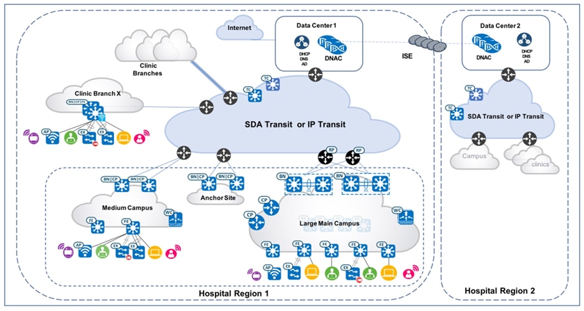
The test topology for the Cisco SD-Access Healthcare Vertical solution includes two Catalyst Center three-node clusters, which manage hospital region 1 and region 2 respectively. They are configured as Multiple Catalyst Center and integrated with the same distributed ISE cluster. The Cisco-distributed ISE cluster deployment includes two Policy Administration Nodes (PAN), two Monitoring Nodes (MnT), pxGrid, and multiple Policy Service Nodes (PSN).
Each Catalyst Center cluster manages a fabric consisting of one large-scale hospital main campus site, one medium-scale campus site, one Anchor Site, and 500 small-scale clinic branch sites with Fabric-in-a-box (FiaB). Cisco SD-Access transit is deployed to connect distributed campuses. Remote clinic branches are connected to the main campus through IP networks. The figure illustrates the logical topology of the Cisco SD-Access Healthcare Vertical solution test bed.
Descriptions of the fabric sites:
● The Large Campus Main site has dual borders, dual dedicated control plane nodes, dual wireless controller, and 100 fabric edges.
● The Medium site has dual colocated border and control plane nodes, wireless controller, fabric edges, and extended nodes.
● The Small sites have FiaB on hardware stacking with embedded wireless controller and extended nodes.
● The Anchor Site has dual colocated anchor borders and control plane nodes and provide anchored service across multiple fabric sites.
● Cisco SD-Access Transit is implemented with dual transit control plane nodes. Main Campus site borders are configured to provide internet access to other campus sites through Cisco SD-Access Transit.
In the pictured deployment example, Cisco SD-Access multicast with external RP is configured and the server room that resides within the fabric is deployed across multiple campus sites. The large fabric site deploys native multicast to achieve the best possible network performance. The smaller fabric site deploys headend multicast to simplify site management.
Scale
Solution test verified the scale numbers listed in this table. To view the scale numbers for the Catalyst Center appliance, see the Cisco Catalyst Center Data Sheet.
| Category |
Value |
| Device inventory |
5,000 |
| Number of devices per fabric site |
100 |
| Multiple Catalyst Center appliances |
2 |
| Number of buildings and floors |
2,000 |
| Number of VNs per fabric site |
64 |
| Number of IP pools per fabric site |
500 |
| Number of WLCs per fabric site |
2 |
| Number of fabric sites |
502 |
| Number of APs in inventory |
13,000 |
| Number of endpoints |
100,000 (50,000 wired, 50,000 wireless) |
| Number of SSIDs |
10 |
| Number of SGTs |
4,000 |
Solution key notes
This section describes the key technical notes for the Cisco SD-Access Healthcare Vertical profile's solution validation.
Incremental site deployment and expansion
Healthcare networks naturally have a high number of sites, and the demand for network expansion to new locations is constant.
Catalyst Center automation workflows provide a cost-effective, flexible, and scalable solution to deploy new fabric sites with Cisco SD-Access enabled in multiple locations. The Cisco SD-Access Healthcare Vertical solution executed these workflows to expand new Cisco SD-Access sites:
● Main Site provides internet access and shared services to distributed campuses using Cisco SD-Access Transit: Newly deployed fabric sites need to be able to reach these domains: shared service (such as Catalyst Center, Cisco ISE cluster, DNS, AD and DHCP servers), service within the same VN across fabric sites, and internet access. Catalyst Center provides an optimized and scalable solution with Cisco SD-Access Transit, which seamlessly enable full reachability for the new fabric site.
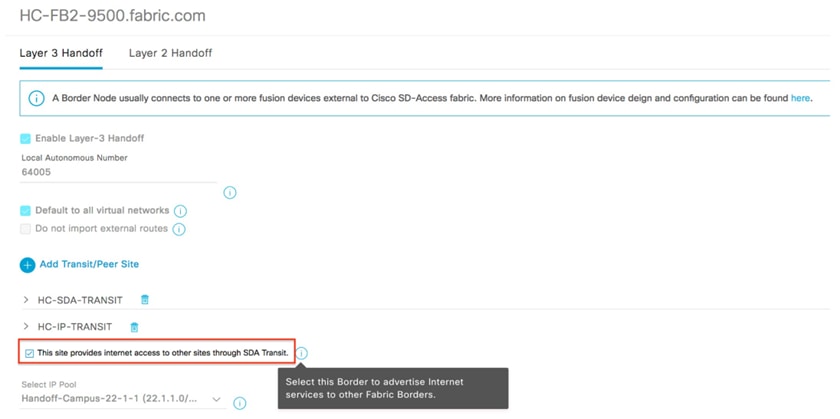
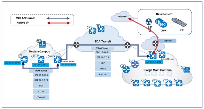
● Enable internet access for new fabric sites: In a typical large medical deployment, the Headquarters or Main Campus sites access the internet through borders that are connected directly to the internet or through data center firewalls. To simplify new fabric deployment, Catalyst Center provides this option in the border configuration workflow: This site provides internet access to other sites through SDA Transit. By checking this check box, the local site border will act as the default gateway—not just for the local site, but also for all other fabric sites connected through Cisco SD-Access Transit within the same fabric domain. In large healthcare deployments, just like any large campus, the site borders in the Main Campus site are configured with this option selected: This site provides internet access to other sites through SDA Transit. For any new fabric site that is deployed, it will immediately be able to route any unknown traffic or internet access through the site border in the Main Campus site. These two figures illustrate the GUI workflow and packet flow showing the Main Campus site providing the internet access to distributed sites.
● Enable Cisco SD-Access Transit: When setting up site borders for a new campus site, enable Cisco SD-Access Transit and specify Transit Control Plane Nodes. For a generic workflow that enables Cisco SD-Access, see the Cisco Software-Defined Access for Distributed Campus Prescriptive Deployment Guide. Transit Control Plane nodes take care of interfabric communication and associate the aggregate prefixes with a border node’s RLOC. Site-local Control Plane nodes take care of intrafabric communication and associate the endpoint identity (EID) with a fabric edge node. Intersite data traffic is encapsulated between sites using the fabric VXLAN encapsulation carrying macro (VN) and micro (SGT) policy constructs. With Cisco SD-Access Transit enabled, newly deployed fabric sites can communicate across sites for services within the same VN. These new sites can also access shared services at a central fabric site through proper route leaking between VNs.
● Uncarpeted space expansion: Healthcare has undergone dramatic changes at care delivery sites, especially while dealing with COVID-19. As a result, healthcare systems have been moving medical services to outdoor spaces like parking lots and warehouses. Cisco SD-Access extended nodes enable mobility by offering a Layer 2 port extension and increasing the port density to existing fabric edge nodes, while also providing segmentation and group-based policies to the endpoints connected to these switches. Catalyst Center provides a zero-touch plug-and-play automated workflow to discover, provision, and add extended nodes to the fabric.
Catalyst Center has two different support options for extended nodes: classic extended nodes (ENs) and policy extended nodes (PENs). In addition to the operation and management provided by classic extended nodes, PENs directly support SGT policy enforcement with SGACLs. This local support of SGACLs provides direct east-west traffic enforcement on PENs.
Extended nodes are connected to a single fabric edge switch through an 802.1Q trunk port. This port can be deployed as an EtherChannel if two or more links are aggregated at the upstream fabric edge. Catalyst Center automates the trunk and the creation of the EtherChannel. After extended nodes have been onboarded through the workflow, endpoints (including fabric-mode APs and other Power over Ethernet (PoE) devices) can connect directly to the extended node, expanding the wired and wireless services to uncarpeted spaces as needed. For Cisco SD-Access extended node deployment details, see the Cisco Extended Enterprise Non-Fabric and SD-Access Fabric Design Guide.
Anchored services for wired and wireless hospital endpoints
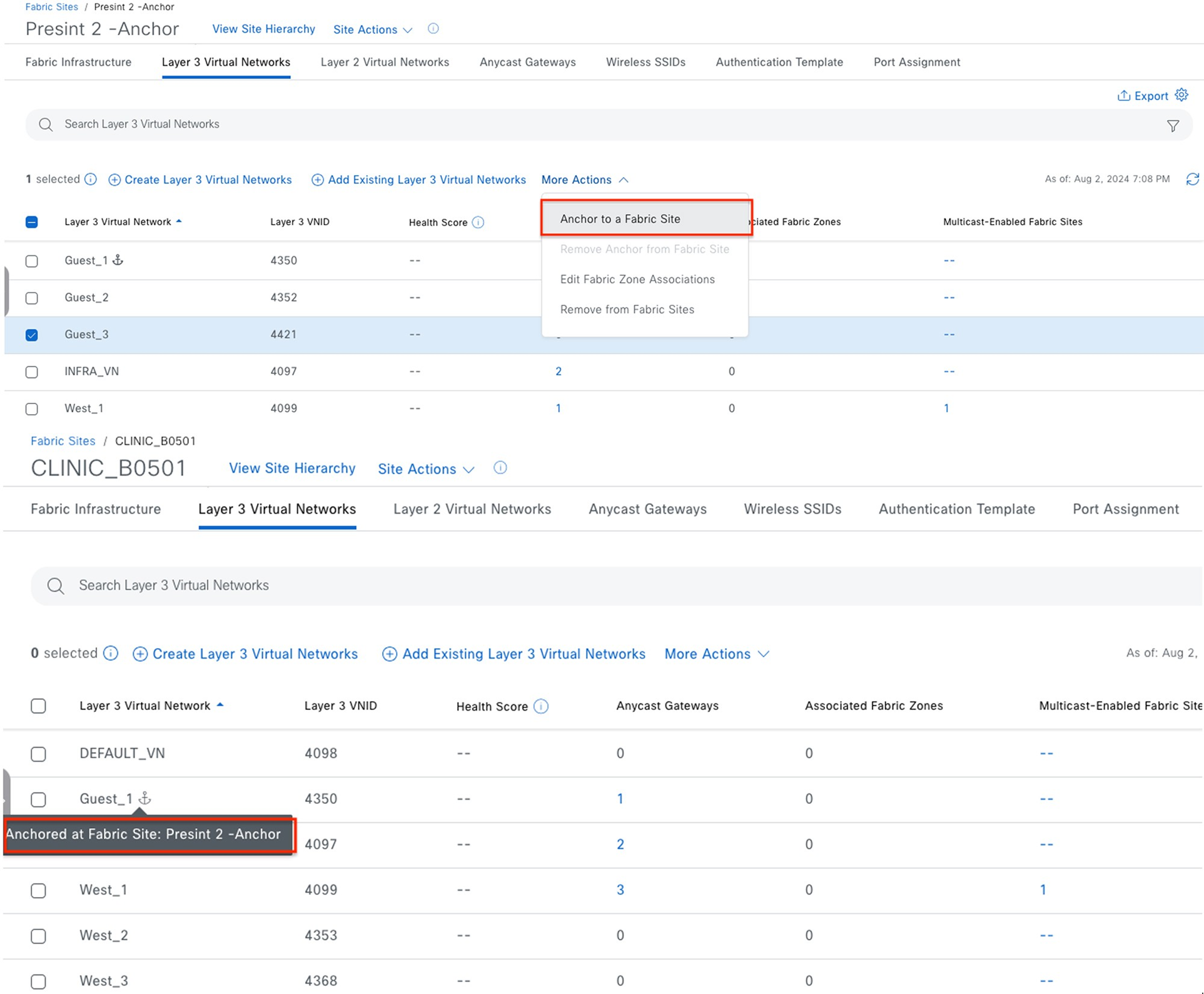
Healthcare customers often need to manage extensive guest services across all of their sites. Guest endpoints (which are bound to each individual fabric site) typically get IP addresses from the local site address pool and direct all traffic towards the local site borders. This adds complexity for address management and policy enforcement across multiple sites. To address this challenge, Catalyst Center provides the Multisite Remote Border solution that utilizes VN anchors. This solution allows traffic from a VN at multiple sites to be aggregated back to a central location (an anchor site) using a single common subnet, rather than having to define and use per-site subnets for that VN. With a simplified and centralized subnet structure, VN anchors facilitate guest service deployments across multisites. They also provide consistent and secure segmentation for guest traffic in large-scale healthcare environments.
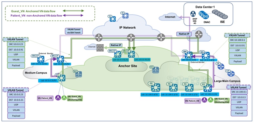
Using anchored service, traffic for all of the endpoints belonging to the anchored VN at each site is aggregated and tunneled back to the central anchor border residing at the anchor site over VXLAN. While an anchor site functions very much like a traditional fabric site, it forms a virtual fabric site serving a particular VN. This virtual fabric site has its own site border and control plane (anchor border and CP), which are located at the anchor site. What is special about the anchor site is that the edges and wireless controller for this site are dispersed across multiple fabric sites.
Multisite Remote Border is enabled on a per-VN basis. For an anchored VN (such as Guest_VN), all edges at anchoring sites use the anchor CP/border for control and data plane communication. Wireless controllers at the anchoring sites communicate with the anchor CP for wireless endpoint registration. For nonanchored traditional VNs, edges and wireless controllers use their own site-local
CP/border for control and data plane communication. Like other RLOCs of devices operating in a fabric role, the Loopback 0 address of the anchor border/CP node must be reachable through a /32 route in the global routing table of the edge nodes residing at the anchoring sites.
When a wireless guest has Multisite Remote Border enabled, the guest endpoint joins the guest SSID, completes Central Web Authentication (CWA) through Cisco ISE, and is then associated with the anchored guest VN. Guest traffic is tunneled to the anchored border and makes its way to the internet through a firewall. The first figure shows the Catalyst Center GUI screens from which you can enable Multisite Remote Border. The second figure illustrates the packet flow of both an anchored and unanchored VN.
Medical server room: multicast across multiple sites
Cisco SD-Access supports Multicast PIM Any-Source Multicast (PIM-ASM) and PIM Source-Specific Multicast (PIM-SSM) in both the virtual overlay network and physical underlay network. The multicast source can either be outside of the fabric domain (typically in the data center) or within the fabric overlay (typically connected directly to an edge node or extended node). Multicast receivers are usually connected directly to edge nodes or extended nodes across all fabric sites.
Catalyst Center offers two different multicast forwarding methods, tailored for different customer network designs on a per-VN basis. The first method is headend multicast (or ingress replication), which offers a clean overlay-only multicast forwarding solution as it does not require multicast in the underlay network. The second method is native multicast, which offers the most scalable bandwidth and CPU efficiency as the multicast replication is done throughout the underlay network.
Note: Even though multicast forwarding is enabled on a per-VN basis, the two forwarding methods are mutually exclusive within a given fabric site.
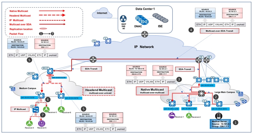
The Cisco SD-Access Healthcare Vertical design has validated these use case scenario, which demonstrates a multicast deployment in a large-scale multisite hospital network using Catalyst Center. In this scenario, a medical server room is connected to a fabric edge in the overlay at the Large Main Campus site. The servers in the server room are the multicast sources and could be in different VNs, servicing different medical audiences such as patients, administrators, medical staff, or medical school interns. The receivers are located across distributed campus sites. In Figure 7, multicast receivers reside in the hospital's Large Main Campus site as well as its Medium Campus site. The Rendezvous Point (RP) is placed outside of the fabric, so it can consistently serve both existing and newly deployed fabric sites.
Multicast use cases cover these requirements:
● Multiple servers (multicast sources) in different VNs are connected to a single fabric edge through the trunk port at the Large Main Campus site.
● Multicast receivers from the same Campus site where the multicast source resides are deployed.
● Multicast receivers from campus sites are different from the one where the multicast source resides are deployed.
● Cisco SD-Access Transit is deployed across distributed campus sites.
● The multicast RP is located outside of the fabric.
These solutions have been validated and fulfill these requirements:
● Deploy trunk port for server connection: The fabric host onboarding port-assignment workflow provides the option to configure the connected device type as the trunk. As a result, the switch port on the edge or extended node is configured as the trunk. This allows the servers in the server room to connect to fabric edges with different VLAN tags.
● Deploy multicast with headend replication (PIM-ASM in overlay): As mentioned earlier, headend replication for multicast runs on the overlay network and performs multicast-in-unicast encapsulations. In this service room case, the distributed site border will be the First Hop Router (FHR) and replicate each multicast packet in the overlay (S, G). It sends packets through unicast over the VXLAN tunnel (FHR_RLOC, LHR_RLOC) to all Last Hop Routers (LHR) which have the interested subscribers. For a small campus site, the edges are often directly connected to the fabric borders. With its lean and simple topology, this option is ideal for small fabric sites as it doesn't add too much bandwidth overhead on the site borders (FHR). It also has significantly less operational overhead, as it does not require the setup of underlay multicast.
In a case where there are multiple receivers connected to an extended node (with the IGMP snooping function enabled by default), extended nodes complete packet replication on all the ports where the receivers are connected. The figure illustrates the detailed packet data path in the small fabric site using headend replication as the transport option.
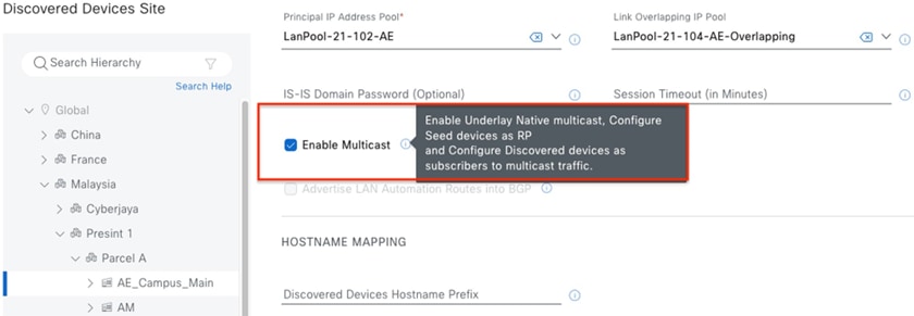
● Deploy native multicast (PIM-ASM in overlay, PIM-SSM in underlay): Native multicast does not rely on the FHR to replicate packets. The entire underlay, including intermediate nodes, is participating in packet replication. Packets get replicated wherever there is a branch-out point on the underlay Source Specific Multicast (SSM) tree. In other words, packets get replicated at the closest node to the receivers and are replicated only when it is necessary. This option is ideal for large campus sites, as it provides the most bandwidth and CPU efficiency for the FHR and the rest of the network.
Native multicast requires PIM-SSM for the underlay multicast transport and performs multicast-over-multicast encapsulations at the FHR. In this particular server room case, as multicast sources (medical servers) are connected to the edge, the fabric edge is the FHR. When the FHR receives the multicast packet on the overlay (S_overlay, G_overlay), it tunnels this packet as the payload in underlay multicast packets (S_underlay, G_underlay). From there, it uses the underlay SSM tree to complete packet replication. The figure illustrates the detailed packet data path in the Main Campus site using Native Multicast as the transport option.
● Multicast across fabric sites through SD-Access Transit: Distributed healthcare campus sites communicate with the RP and Multicast source through Cisco SD-Access Transit. PIM packets are first sent to the local campus site borders and are then tunneled to the Main Campus site borders through VXLAN. The Main Campus site border then forwards the PIM packets to the RP (outside of the fabric, in this case) through IP transit or forwards it to the edge where the source (medical server) is located through VXLAN. Multicast data forwarding across sites uses Cisco SD-Access Transit as well. The figure depicts the detailed multicast data packet path sourced from the Medical Server within the Large Main Campus site, with the receivers at both the Large Main Campus site and the Medium Campus site.
Migration to telemetry-based assurance
Healthcare organizations manage a large number of medical devices and users. Checkup rooms, treatment rooms, and consulting rooms are equipped with many device terminals and monitors. For fabric-wired endpoints, Catalyst Center typically uses inventory and SNMP-based polling methods to retrieve, monitor, and report the health data that's provided in Cisco DNA Assurance health pages. Starting with version 2.1.2.0, Catalyst Center leverages telemetry over NETCONF to support assurance data collection. This new method, Telemetry Data Logger (TDL)-based wired assurance, is recommended for monitoring wired client health as it provides better scale and performance and more real-time status reporting. The Cisco SD-Access Healthcare Vertical has successfully migrated from inventory to TDL-based assurance for 50,000 wired fabric clients in the current Catalyst Center release.
Migrating to TDL-based assurance on fabric devices also enables Power Over Ethernet (PoE) telemetry and analytics in the network. The listed categories can be monitored for PoE-capable devices in the Cisco Catalyst Assurance PoE page: PoE Operational State Distribution, PoE Powered Device Distribution, Power Load Distribution, and PoE Insights. This information offers comprehensive insights into the power distribution and power usage details for all PoE devices across all sites in the network.
Network as Code for efficient deployments
The Healthcare network deployments embrace a Network as Code (NaC) approach, ensuring consistent, scalable, and repeatable configurations for healthcare sector infrastructure. By leveraging Ansible Playbooks tailored for Cisco Catalyst Center-based deployments, we automate key stages of the deployment lifecycle, including network operations, routine maintenance, software upgrades, and site expansion. This automation significantly reduces manual effort and the potential for human error, while also enhancing operational efficiency, accelerating change implementation, and aligning with modern DevOps principles for agile network management.
To learn more about our network automation practices, we encourage you to explore our automation repository. It features practical examples, reusable Ansible Playbooks tailored for healthcare network deployments, and proven best practices designed to support scalable, efficient network operations. Visit the repository to gain deeper insights and begin your automation journey with confidence.
For more details, see these repositories:
https://github.com/DNACENSolutions/NetworkasCode_CVPs
https://github.com/DNACENSolutions/NetworkasCode_CVPs/tree/main/nac_healthcare_sda
Related Cisco SD-Access Documentation
● Cisco SD-Access Solution Design Guide (CVD)
● Cisco Software-Defined Access for Distributed Campus Prescriptive Deployment Guide
● Cisco Extended Enterprise Non-Fabric and SD-Access Fabric Design Guide