Solution Overview
This guide provides an IPv6 solution for customers who prefer software-defined networks over traditional networks. The solution architecture is based on Cisco Software-Defined Access for the campus architecture, Cisco SD-WAN for WAN, and Cisco Firepower for secure internet connections. The objective is to enable IPv6-only clients while keeping the underlay infrastructure dual stack during transition. Migrating to a single-stack IPv6 architecture for both overlay and underlay will be performed when an end-to-end, IPv6-only environment is fully supported.
Technology Overview
The IPv6 solution is a cross-architectural design encompassing multiple domains, such as the campus, data center, firewall, WAN, and internet. The endpoints across campus sites are IPv6-only clients, and the underlay infrastructures are dual stack where required.
IPv6 in Cisco SD-Access
Over time Catalyst Center architecture has evolved from traditional campus LAN designs to the Cisco SD-Access design architecture. Cisco SD-Access uses Catalyst Center to design, provision, and apply policies, as well as provide wired and wireless network assurance for an intelligent campus network. In this solution, the Cisco SD-Access fabric underlay uses IPv4 addressing. Catalyst Center utilizes IPv4 to integrate with Cisco ISE, manage devices, and provision the Cisco SD-Access fabric. In the Cisco SD-Access fabric, overlay IPv6 traffic is transported in IPv4 Virtual Extensible LAN (VXLAN) tunnels.
IPv6 in Cisco SD-WAN
The Cisco SD-WAN architecture consists of separate orchestrations, managements, controls, and data planes. The vBond controller allows you to automatically onboard Cisco SD-WAN routers in to the Cisco SD-WAN overlay. The vManage controller is responsible for central configuration and monitoring. The vSmart controller is responsible for the centralized control plane of the Cisco SD-WAN network. The Cisco SD-WAN edge device establishes a secure data-plane connectivity with other Cisco SD-WAN edge devices. The overlay IPv6 traffic can be transported in IP security (IPsec) tunnels established over IPv4 or IPv6 transports based on local and remote Cisco SD-WAN edge device configurations.
The Cisco SD-Access and Cisco SD-WAN technology domains are integrated to enable communication between Cisco SD-Access sites across the Cisco SD-WAN fabric. This solution testing validates the IPv6 integration of the Cisco SD-Access and Cisco SD-WAN technology domains and using the Cisco Firepower appliance as the Cisco SD-Access Fusion device at the main campus site. This testing follows the Cisco SD-Access SD-WAN Independent Domain Pairwise Integration Guide to implement the Border Gateway Protocol (BGP) and Virtual Routing and Forwarding (VRF) Lite between devices. For more information, see the Cisco SD-Access SD-WAN Independent Domain Pairwise Integration Guide.
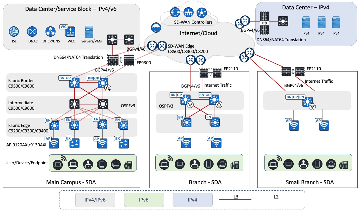
The logical topology of the solution testbed represents the reference customer network design with multiple Cisco SD-Access sites of different sizes. The Cisco SD-WAN fabric connects multiple Cisco SD-Access sites and remote data centers to enable the transportation of IPv4 and IPv6 traffic. The campus and branch sites are implemented with redundancy wherever possible, including uplink redundancy and node redundancy. Catalyst switches and routers are used in this solution. The main campus deploys Cisco Catalyst 9000 switches and the Cisco Catalyst 9800 Wireless Controller. The Cisco SD-WAN edge routers include the Cisco Catalyst 8000 and Cisco ASR 1000 Series Routers.
At each site, Cisco Firepower appliances implement security requirements for internal and internet traffic. These appliances enable network address translation 64 (NAT64) that works with DNS64 to provide IPv6-only clients reachability to IPv4 servers. Cisco Firepower appliances are centrally managed by the Firepower Management Center (FMC).
In this architecture, the data center contains centralized services, such as the domain name system (DNS), Dynamic Host Configuration Protocol (DHCP), and other applications. Catalyst Center, wireless controllers, Cisco ISE, and Cisco FMC are deployed in the data center collocated with the main site campus, which supports both IPv4 and IPv6 services. For this solution, Catalyst Center and Cisco ISE are configured and integrated with IPv4 addresses.
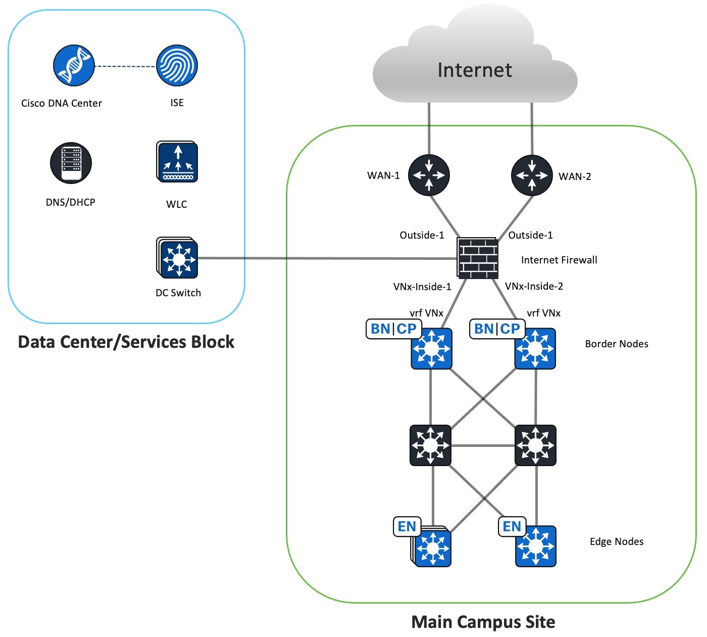
Main Campus Site Design Overview
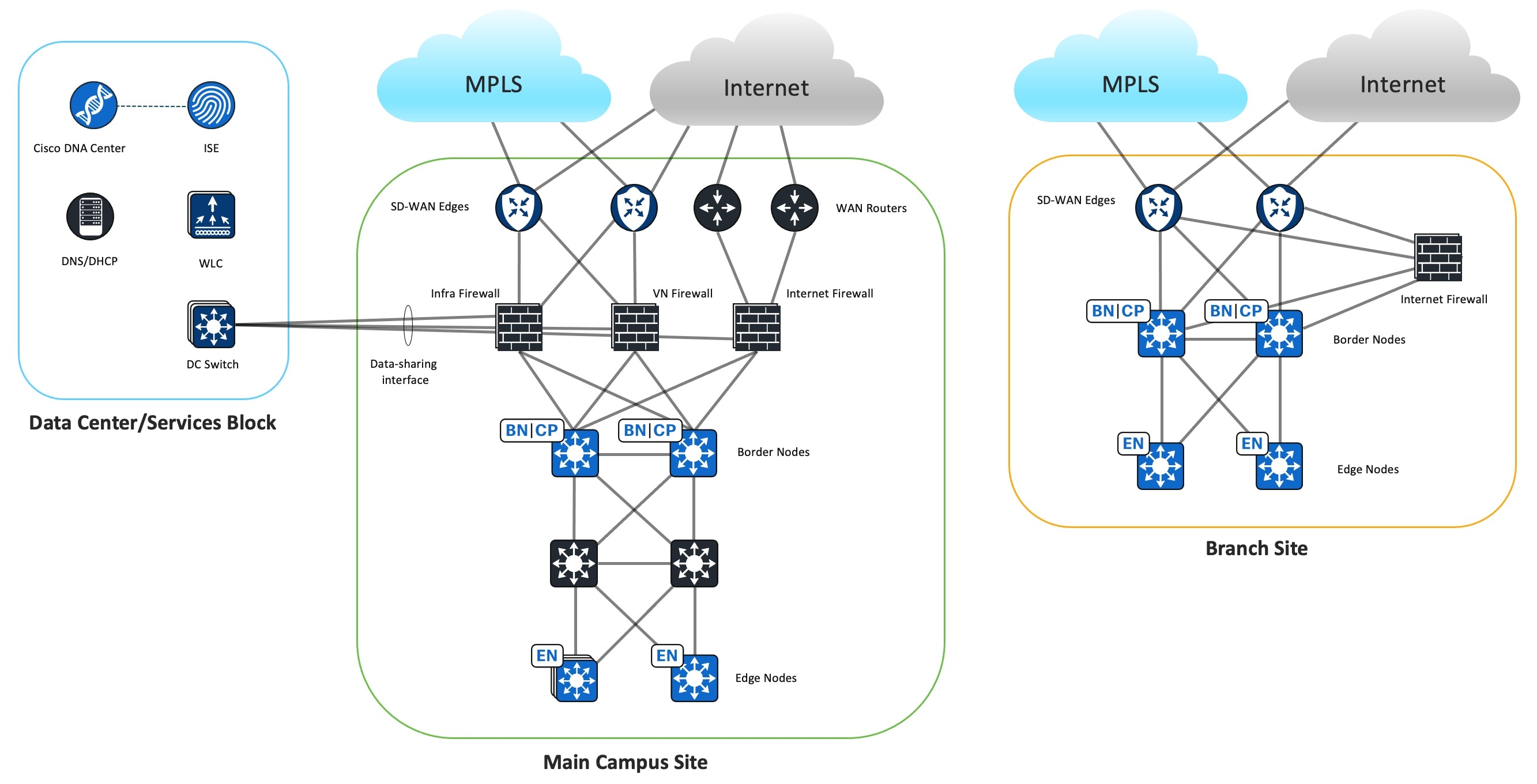
The main campus site design uses the Cisco Firepower 9300 as the Cisco SD-Access Fusion device. This design aims to achieve macrosegmentation between Cisco SD-Access virtual networks (VNs) while granting access to shared resources in the data center and internet. The external BGP (eBGP) is the preferred routing protocol to facilitate prefix reachability exchange between Cisco SD-WAN edge routers, the firewall, and Cisco SD-Access fabric borders. This protocol offers fast convergence with Bidirectional Forwarding Detection (BFD), granular prefix filtering, and BGP attributes for influencing the best path selection.
Control Plane and Data Plane Integrations
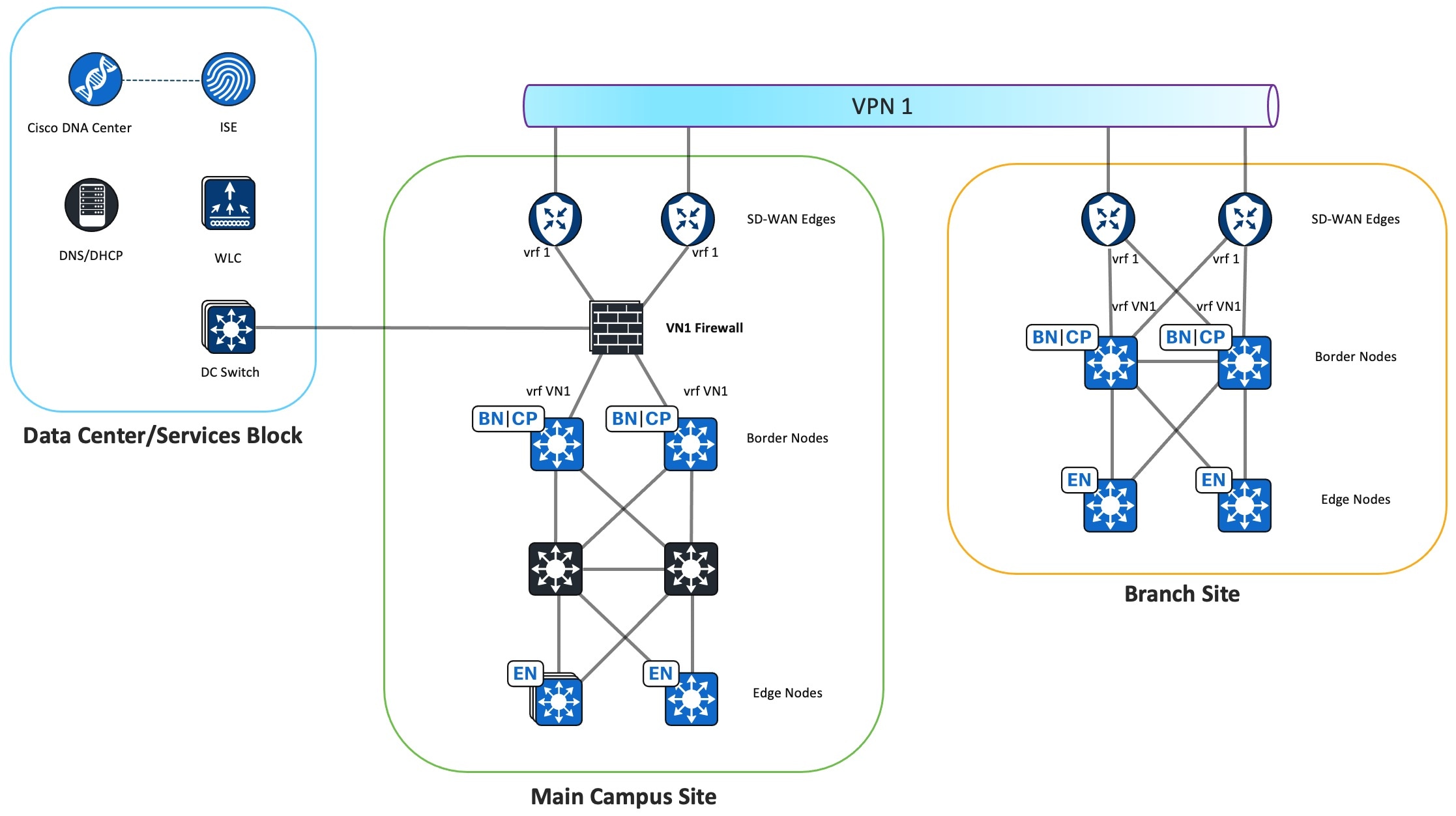
The firewall is placed between the Cisco SD-Access fabric border and Cisco SD-WAN edge devices to connect the Cisco SD-Access VN to a Cisco SD-WAN VPN. This placement enables the same VN communications across different sites. At this location, the firewall can apply security policies to permit or deny traffic between the same Cisco SD-Access VN hosts located in different sites across Cisco SD-WAN. The firewall also secures the traffic going to the shared-services network in the data center.
In this solution testing, for the control plane separation, one firewall instance is created for each Cisco SD-Access VN. From the firewall instance's perspective, all routing takes place in the global routing table. To create a one-to-one mapping between the Cisco SD-Access VN and Cisco SD-WAN service VPN, one firewall subinterface connects to the fabric border VN interface and another firewall subinterface connects to the Cisco SD-WAN edge device service-facing interface. The firewall instance establishes BGP peering sessions to the Cisco SD-Access borders and Cisco SD-WAN edge devices to exchange routes between the Cisco SD-Access VN and the Cisco SD-WAN service VPN. The Cisco SD-WAN edge device performs the mutual BGP to Overlay Management Protocol (OMP) route redistribution for the service VPN.
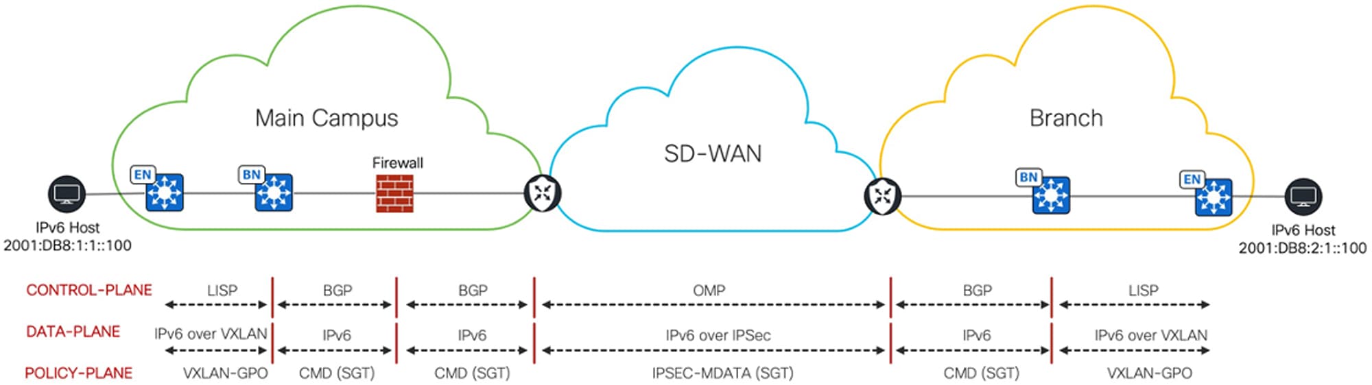
As the IPv6 packet enters the fabric edge at the main site, it is encapsulated in VXLAN and sent across the Cisco SD-Access fabric to the fabric border. The fabric border decapsulates the frame and directs it to the firewall, which in turn forwards it to the Cisco SD-WAN edge device service-facing interface. Then the IPv6 packet is encapsulated in IPsec and sent across the Cisco SD-WAN fabric. The receiving Cisco SD-WAN branch edge performs decapsulation and sends the IPv6 packet to the branch fabric border, which then encapsulates it in VLXAN and forwards it to the branch fabric edge.
The IPv6 Enterprise wireless traffic and the IPv4 wireless traffic are transported through the Cisco SD-Access fabric using the same method. Both IPv6 and IPv4 wireless traffic travel from the access point (AP) through a VXLAN tunnel to the fabric edge.
Note that this setup maintains end-to-end control plane and data plane separations across sites.
The Policy Plane Integration
Security Group Tag (SGT) Inline Tagging is enabled on the interfaces between the Cisco SD-WAN edge device, firewall, and Cisco SD-Access fabric border devices. The SGT is transferred from the fabric VXLAN header and placed in the Cisco Meta Data (CMD) field of the Ethernet header by the main site fabric border and sent to the firewall. The firewall sends the frame to the Cisco SD-WAN edge device, where the SGT is copied from the Ethernet CMD field to the IPsec CMD field and carried across the Cisco SD-WAN fabric. On the receiving Cisco SD-WAN branch edge, the SGT is transferred from the IPsec CMD field to the Ethernet CMD field. This Ethernet frame is sent to the branch fabric border, where the SGT is transferred from the Ethernet CMD field to the VXLAN header and forwarded to the fabric edge. Note that this setup maintains end-to-end policy plane separation across sites.
Cisco SD-Access Underlay Traffic Across Cisco SD-WAN
At the main campus site, Catalyst Center is in the data center. Communication is required between Catalyst Center and all Cisco SD-Access fabric devices located at remote sites across Cisco SD-WAN for device discovery, management, and monitoring. For this purpose, a dedicated service VPN is used to carry Cisco SD-Access underlay traffic across the Cisco SD-WAN fabric. The Infra Firewall instance connects to this Cisco SD-WAN service VPN interface to open the path between the shared-services network and the remote Cisco SD-Access fabric devices across Cisco SD-WAN. The Infra Firewall instance also connects to the main site fabric border global interface to enable reachability to Cisco SD-Access fabric devices in the main site.
The Firewall as the Cisco SD-Access Fusion Device
In Cisco SD-Access, the Fusion router performs route leaking between global shared-services routes and Cisco SD-Access VN routes. When using the Cisco Firepower appliance as the Cisco SD-Access Fusion device, routes are not leaked between firewall instances because each firewall instance has only a global routing table. Instead, routes are exchanged through the Cisco Firepower appliance data-sharing interfaces. Each firewall instance shares the same data-sharing interface connecting to the data center switch to access the shared-services network. Each firewall instance has a unique IP address on the same subnet and forms eBGP peering with the data center switch to advertise local Cisco SD-Access VN routes and to receive global shared-services routes.
Stateful inspection on the firewall requires that a return packet must arrive on the same interface as the original packet. As there are two internal firewall interfaces connected to fabric borders and two external firewall interfaces connected to Cisco SD-WAN edge devices, the firewall drops return packets that arrive on a different interface. To use redundant firewall links, equal-cost multipath routing (ECMP) zones are deployed to enable ECMP routing and load balancing of traffic across multiple interfaces. In this solution testing, the two internal firewall interfaces, connected to the Cisco SD-Access fabric borders, are placed in one ECMP zone while the two external firewall interfaces, connected to Cisco SD-WAN edge devices, are placed in another ECMP zone. Additionally, the eBGP multipath is set to two on the firewall BGP settings to enable two equal-cost paths to the destination.
Firewall Instance Types
At the main site, three types of firewall instances are deployed: Infra Firewall, VN Firewall, and Internet Firewall. The following figure illustrates the function of each firewall instance.
Infra Firewall Instance

-
The Infra Firewall instance provides Cisco SD-Access underlay connectivity for Catalyst Center to discover Cisco SD-Access fabric devices at the main site and remote branch sites.
-
The Infra Firewall instance connects to the Cisco SD-Access fabric border global interface and to the data center switch toward the shared-services network.
-
The Infra Firewall instance also connects to Cisco SD-WAN edge service VPN that is dedicated for Cisco SD-Access underlay traffic to allow Catalyst Center to discover Cisco SD-Access fabric devices at the remote branch sites. This solution validation uses VPN 10 to transport Cisco SD-Access underlay traffic.
-
The Infra Firewall instance permits traffic between the Cisco SD-Access underlay network and shared-services network in the data center.
-
Permit local and remote Cisco SD-Access fabric devices reachability to Catalyst Center, Cisco ISE, the DNS, and the DHCP.
-
Permit AP-to-wireless controller reachability.
-
Permit AP-to-DHCP server reachability.
-
VN Firewall Instance
-
The VN Firewall instance connects the Cisco SD-Access VN to the Cisco SD-WAN VPN and provides VN connectivity to the shared-services network in the data center.
-
There is one VN Firewall instance for each Cisco SD-Access VN and its associated Cisco SD-WAN VPN. The diagram depicts the Cisco SD-Access VN1 to Cisco SD-WAN VPN 1 association.
-
The VN Firewall instance connects to the Cisco SD-Access border VN interface and the Cisco SD-WAN service-facing edge interface.
-
Each VN Firewall instance shares the same data-sharing interface that connects to the data center switch. eBGP peering is formed between the data center switch and fabric border VRF to exchange routes between the Cisco SD-Access VN and shared-services network.
-
The VN Firewall instance permits traffic between the same VN and provides reachability to the shared-services network in the data center.
-
Permit VN traffic to the DHCP and DNS servers.
-
Permit the same VN traffic between different sites.
-
-
The BGP default route is natively filtered from the Cisco SD-Access fabric border VNs because the source of the default route comes from the Internet Firewall instance. As all the firewall instances in the main site use the same BGP autonomous system (AS) number, the BGP prefixes with the same local BGP AS number in the AS Path are dropped. It's important that the default route is not advertised to the Cisco SD-WAN edge devices, so the internet-based traffic doesn't come from remote sites. The internet-based traffic should exit locally at each site.
Internet Firewall Instance
-
The Internet Firewall instance provides internet access to the Cisco SD-Access VN hosts.
-
One Internet Firewall instance services all the Cisco SD-Access VNs.
-
At the main site, the Internet Firewall instance outside interfaces connect directly to the internet routers, and the inside interfaces connect to each of the fabric borders VN interfaces.
-
The Internet Firewall instance advertises local Cisco SD-Access prefixes to the internet router through the eBGP.
-
The Internet Firewall instance receives IPv4 and IPv6 default routes from the internet router through the eBGP.
-
The Internet Firewall instance advertises IPv4 and IPv6 default routes to fabric borders through the eBGP.
-
The Internet Firewall instance denies traffic between different VNs to maintain macrosegmentation.
-
Because the Internet firewall instance knows the routes to all the VNs and advertises the default route to the Cisco SD-Access fabric borders, it's possible to route traffic between the VNs if the Firewall's access control policy permits this option.
-
The implicit deny access control can serve to prevent hosts in one VN from communicating with hosts in another VN. You can also use an explicit deny rule to block communication between different VNs.
-
-
The Internet Firewall instance allows outbound traffic to IPv4 and IPv6 internet.
-
The firewall stateful inspection permits the return of traffic.
-
The Internet Firewall instance performs NAT64 function to allow IPv6 clients reachability to the IPv4 internet.
-
The data-sharing firewall interface provides internet access to the data center.
Deployment of Virtual Routers on the Firepower
This validation uses firewall instances for control plane and data plane separation. For an alternative deployment design, virtual routers can be deployed on the firewall instead of firewall instances. Virtual routers maintain separate routing tables for groups of interfaces on a single firewall. In place of the three firewall instance types, deploy the following user-defined virtual router types on a single firewall:
-
Infra virtual router
-
VN virtual router
-
Internet virtual router
Border Gateway Protocol (BGP) Route Leaking is configured to enable communication between the user-defined virtual routers.
For more information about configuring virtual routers on the Firepower, see the "Virtual Routers" chapter of the Cisco Secure Firewall Management Center Device Configuration Guide.
Branch Site Design Overview
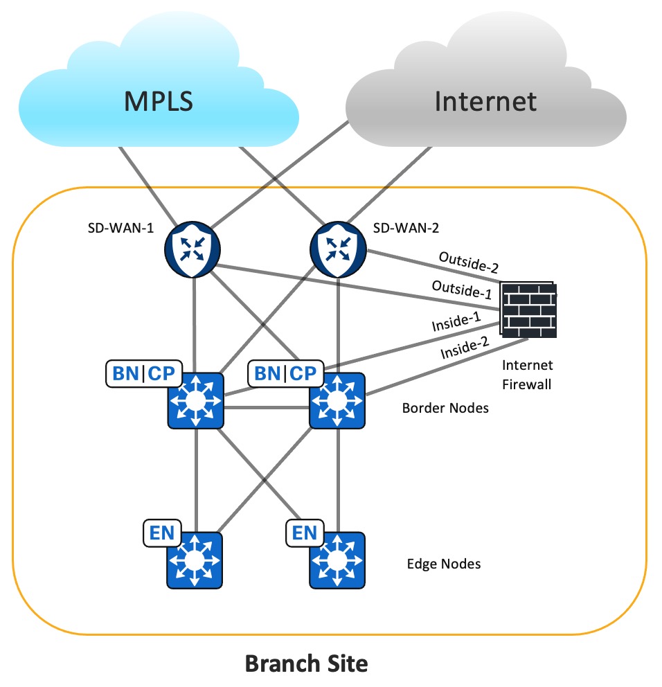
The Branch Site design deploys the Cisco Firepower 2110 strictly as the Internet Firewall. In Cisco SD-Access, the fabric borders are configured as external borders. Two Cisco SD-WAN edge devices connect to the fabric borders to service overlay traffic, enabling communication to Cisco SD-Access networks at remote sites. Transport Locator (TLOC) Extension is not supported for IPv6 transports. Therefore, each Cisco SD-WAN router is configured with two WAN interfaces.
The fabric border VN interfaces connect to the inside firewall subinterfaces. eBGP peering is formed between the firewall and each fabric border VN. The fabric border VN receives the default IPv4 and IPv6 routes to allow the VN to reach the internet. Also, the fabric border has VN interfaces that connect to the corresponding Cisco SD-WAN service-facing edge interfaces. It forms eBGP peering with the Cisco SD-WAN edge devices to advertise local Cisco SD-Access routes and receive specific routes to remote Cisco SD-Access networks in the same VN as well as to the shared-services network in the data center. To prevent the branch site from becoming a transit site for internet traffic from other sites, the fabric border filters BGP default routes to the Cisco SD-WAN edge devices.
Because all VN routes converge in the firewall's global routing table and each fabric border VN has a default route toward the Internet Firewall, traffic can be routed between different VNs. Access policies should be configured to deny traffic between different VNs unless inter-VN traffic is desired.
Branch Firewall Internet Access
Typically, one internet feed from the ISP connects directly to the Cisco SD-WAN edge device at the branch site. Therefore, it's cost efficient to connect the Firewall outside interface to the Cisco SD-WAN edge device to access the global internet. Because Global-to-Service VPN route leaking is not supported for IPv6 currently, this solution connects the firewall outside interface to the VPN0 interface of the Cisco SD-WAN edge device.
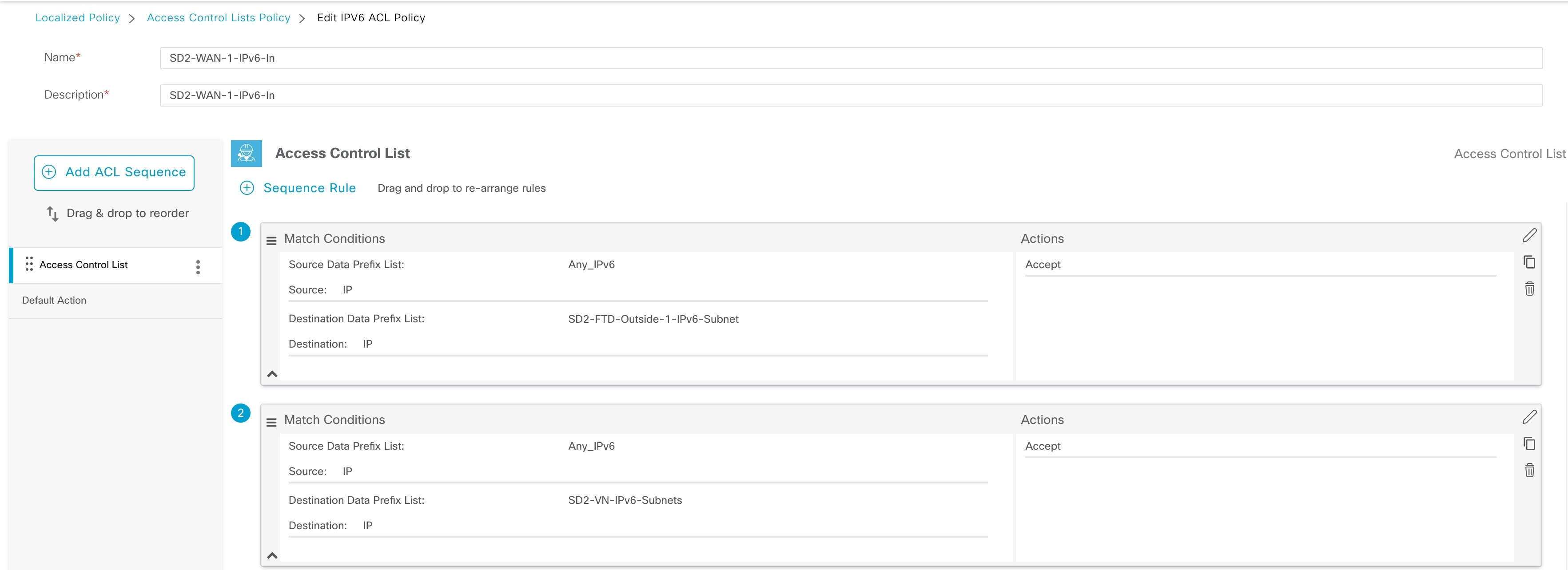
The Internet Firewall Outside-1 interface connects to a SD-WAN-1 edge VPN0 interface. The Internet Firewall Outside-2 interface connects to a SD-WAN-2 edge VPN0 interface. Global routing occurs between the Cisco SD-WAN internet transport interface and the VPN0 interface, connecting to the Internet Firewall outside interface. By default, traffic from the WAN transport interface configured as the tunnel interface to a non-Cisco SD-WAN interface is dropped. To pass traffic between two VPN0 interfaces, a Localized Data policy and explicit Cisco SD-WAN access control list (ACL) are applied to the Cisco SD-WAN edge device.
Hardware and Software Specifications
The solution is validated with the hardware and software listed in the following table. For the complete list of hardware supported, see the Cisco Software-Defined Access Compatibility Matrix.
| Role | Hardware Platform | Software Release | |
|---|---|---|---|
|
Cisco Catalyst Center Controller |
DN2-HW-APL |
2.3.7.7 |
Catalyst Center 2.3.7.9 |
|
DNA-SW-OVA |
2.3.7.7 |
Catalyst Center 2.3.7.9 |
|
|
Cisco Identity Service Management, RADIUS Server |
Virtual (ISE-VM-K9) platform |
3.3 Patch 4 |
Cisco Identity Services Engine 3.3 Patch 4 |
|
Cisco SD-WAN NMS Controller |
vManage |
20.12 |
20.12 |
|
Cisco SD-WAN Edge |
ASR1002-X |
17.9.5, 17.12.4 |
17.12.5a |
|
Cisco SD-WAN Edge |
C8300, C8500 |
17.12 |
17.12.5a |
|
Cisco SD-Access Fabric Border Node |
C9500H/C9600 |
17.6.6a, 17.9.4a |
17.9.5, 17.12.4 |
|
Cisco SD-Access Fabric Control Plane Node |
C9500H/C9600 |
17.9.5, 17.12.4 |
17.9.6a, 17.12.5, 17.15.3 |
|
Cisco SD-Access Fabric Edge |
C9200, C9300, C9400 |
17.9.5, 17.12.4 |
17.9.6a, 17.12.5, 17.15.3 |
|
Cisco Industrial Ethernet 4000 Extended Node |
IE4000 |
15.2(8)E1 |
15.2(8)E5 |
|
Cisco Wireless Controller |
C9800-40, C9800-CL |
17.9.6, 17.12.4 |
17.9.6, 17.12.5 |
|
Cisco Firepower Threat Defense Security Appliances |
FPR9300, FPR2110 |
7.2 |
7.2 |
|
Cisco Secure Firewall Management Center |
FMC Virtual |
7.2 |
7.2 |
Scale
The solution test verified the scale numbers listed in the following table on a 44-core second-generation Catalyst Center appliance. For the software and hardware capacity, see the Cisco Catalyst Center Data Sheet.
| Category | Scale Numbers |
|---|---|
|
VNs per site |
5 |
|
Wireless controllers per site |
2 per HA |
|
Fabric sites |
10 |
|
APs per site |
200-1000 |
|
IPv6 endpoints |
20,000 |
|
SSIDs per site |
4 |
|
SGTs |
100 |
|
Traffic profile |
Unicast and multicast |
The Catalyst Center on ESXi virtual appliance supports the same scale numbers as a 44-core second-generation physical Catalyst Center appliance for small-scale environments. For more information, see the “Deployment Requirements” section in the Cisco Catalyst Center 2.3.7.x on ESXi Deployment Guide.
Solution Use Case Scenarios
The following use cases were validated on the IPv6 vertical profile.
-
Automated secure Cisco SD-WAN transporting IPv4 and IPv6 traffic
-
Fabric-enabled wireless deployment for IPv6 Enterprise users
-
Network visibility, monitoring, and troubleshooting for IPv6 devices and endpoints
-
IPv6 application visibility and health
-
Network robustness for IPv6 networks
-
Secure onboarding for various IPv6-only endpoints
-
End-to-end IPv6 traffic and secure internet access
-
End-to-end inline SGT traffic enforcement between Cisco SD-Access sites across Cisco SD-WAN
-
IPv6-only clients access of IPv6 applications and legacy IPv4 applications
-
IPv6 application performance optimization with quality of service (QoS) and path selection
-
IPv6 endpoints and addresses scale
-
Day-n operations for the following operations: Image Upgrade, Configuration Management, Backup and Restore, and Network Expansion.
Solution Key Notes
This section describes the key technical notes useful for deploying the IPv6 solution.
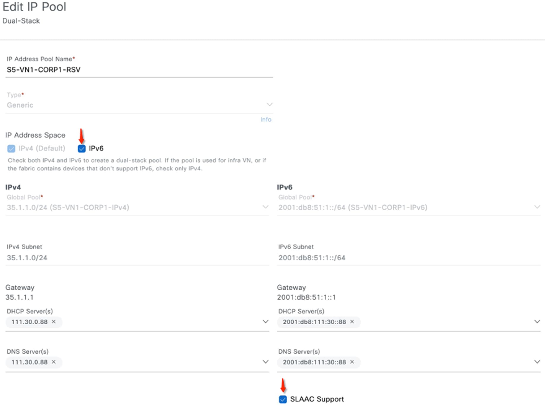
Configure the IPv6 Address Pool
You can reserve an IP pool for the Cisco SD-Access site in Catalyst Center Release 2.3.5.x. This reservation requires specifying both IPv4 and IPv6 pools, which creates a dual-stack IP pool.
To restrict the client to use only IPv6 addresses, you can either disable IPv4 addressing on the client or configure a dummy IPv4 pool and a dummy DHCPv4 server. To enable Stateless Address Auto-Configuration (SLAAC) for the user subnet, in the IPv6 area, check the SLAAC Support check box for the IPv6 pool.
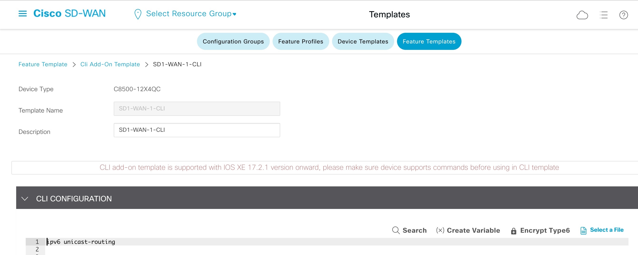
Enable IPv6 Unicast Routing on the Cisco SD-WAN Edge Device
Currently, for the Cisco SD-WAN edge device, IPv6 unicast routing is enabled with the ipv6 unicast-routing command through the device CLI or through the Cisco SD-WAN GUI using the Cli Add-On Template.
Enable IPv6 Strict Control on the Cisco SD-WAN Edge Device
If dual stack is configured on Transport VPN0 WAN interface, IPv4 takes precedence over IPv6 for both control and data connections. For Cisco IOS XE SD-WAN Devices Release 17.10 and later and Cisco SD-WAN Controllers Release 20.10 and later, you can configure the Cisco SD-WAN controllers and Cisco SD-WAN edge devices to prefer IPv6 addressing over IPv4 addressing for forming control connections through the IPv6 Strict Control feature. When IPv6 Strict Control is enabled, the data plane connection between dual-stack Cisco SD-WAN edge devices are established using IPv6 transport.
On the Cisco SD-WAN edge device, IPv6 Strict Control is enabled through the device CLI or through the Cisco SD-WAN GUI using the Cli Add-On Template.

Route Traffic Between Two VPN0 Interfaces on the Cisco SD-WAN Edge Device
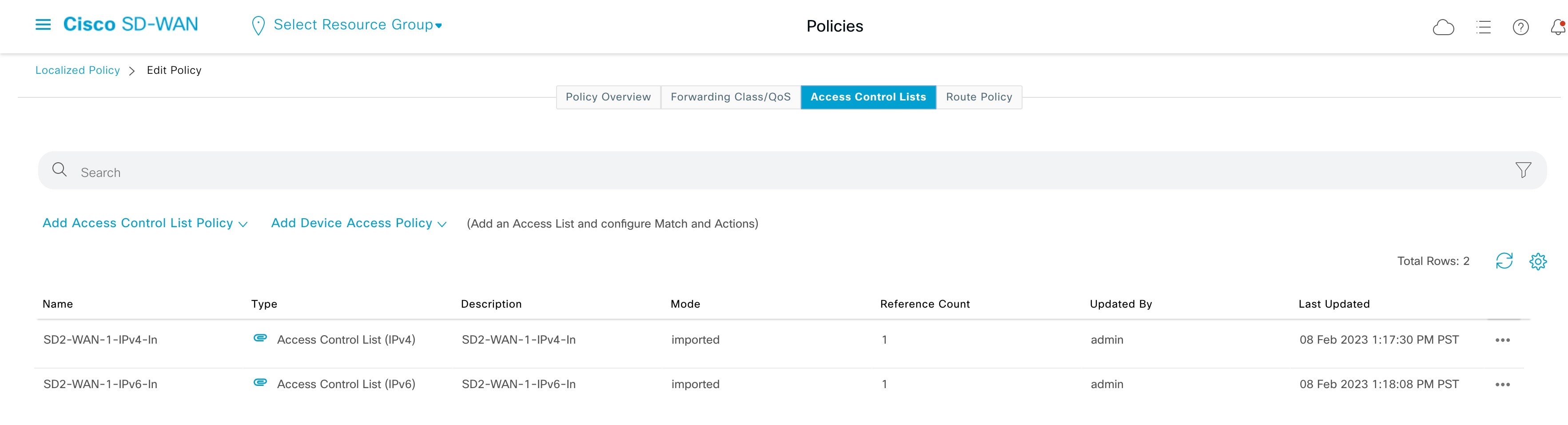
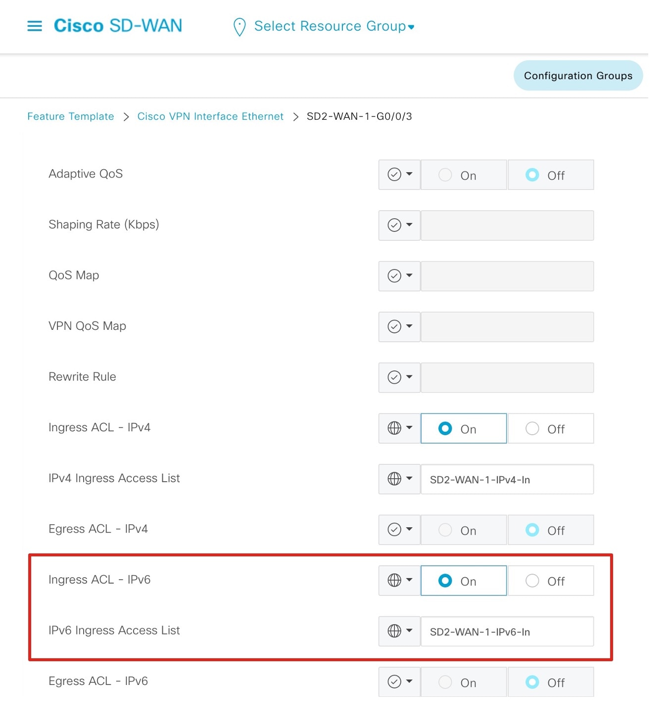
Dropping packets from the WAN transport tunnel interface to a non-Cisco SD-WAN interface is expected behavior. You can change this behavior by applying the Localized Data policy to the device and applying an explicit Cisco SD-WAN inbound ACL to the WAN transport interface. The ACL permits any IPv6 traffic to the firewall outside interface subnet and internal IPv6 prefixes.
Use following procedure to enable the firewall to connect to the Cisco SD-WAN edge device VPN0 interface and then route it out to the IPv6 internet through the Cisco SD-WAN edge internet WAN transport.
Procedure
|
Step 1 |
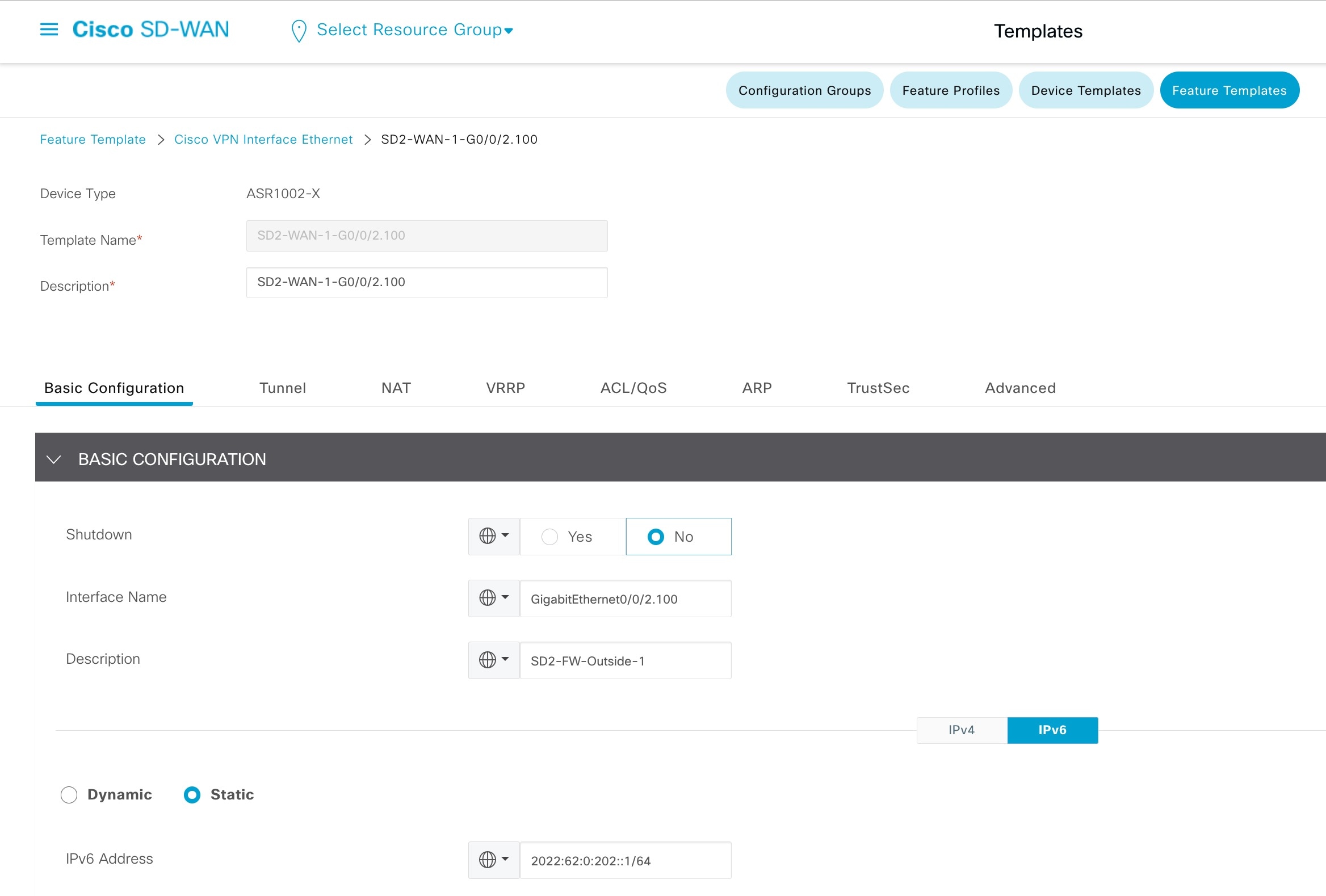
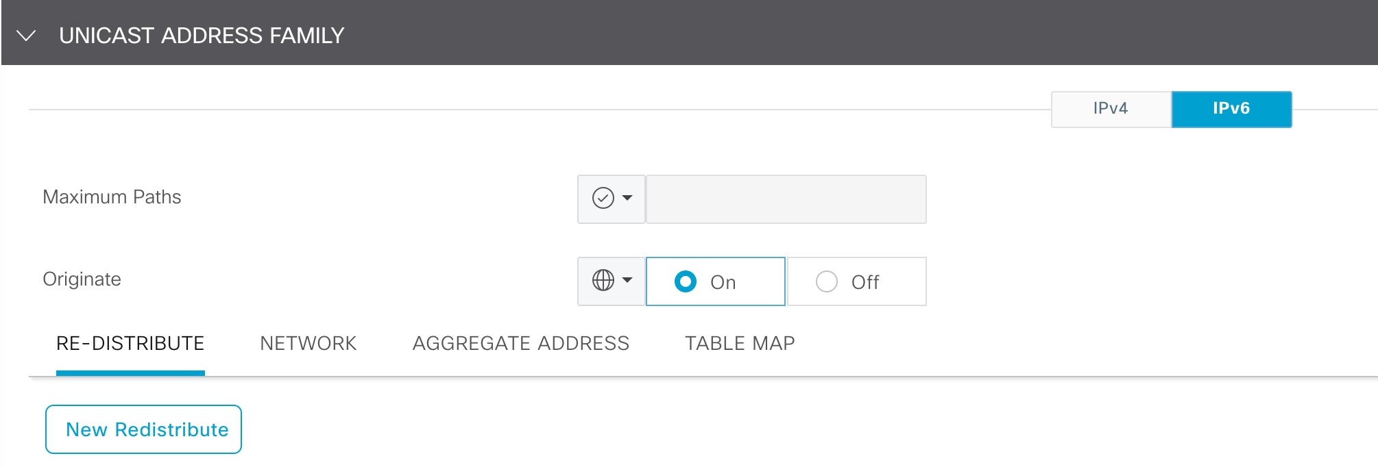
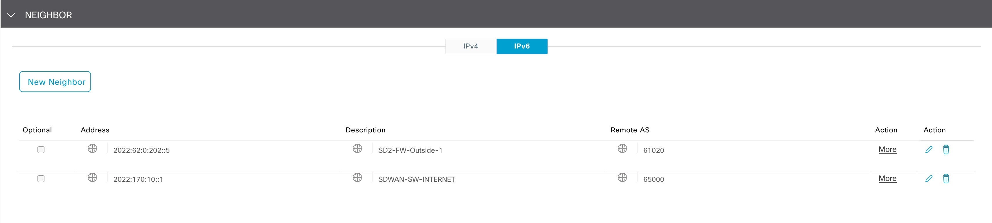
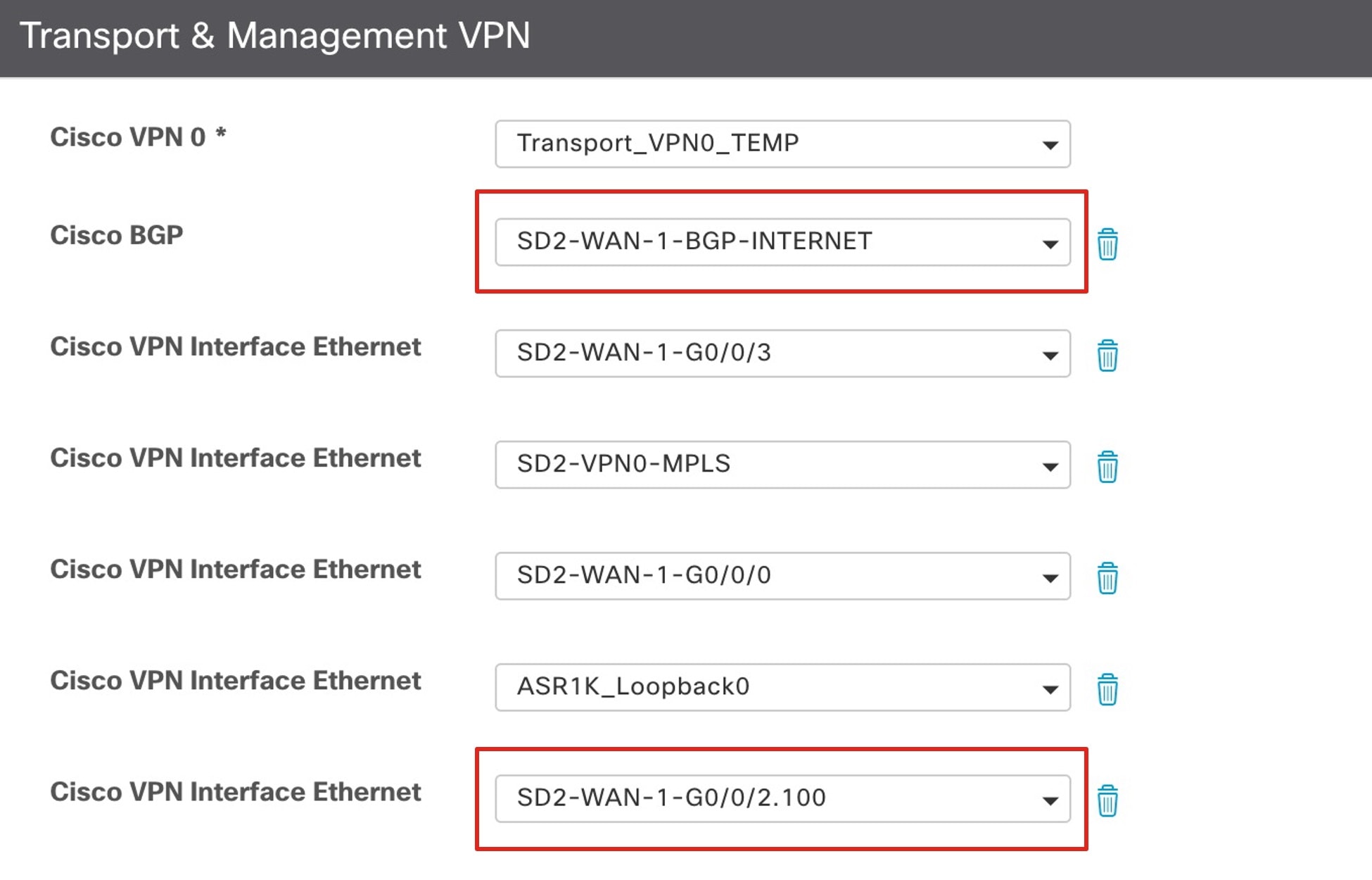
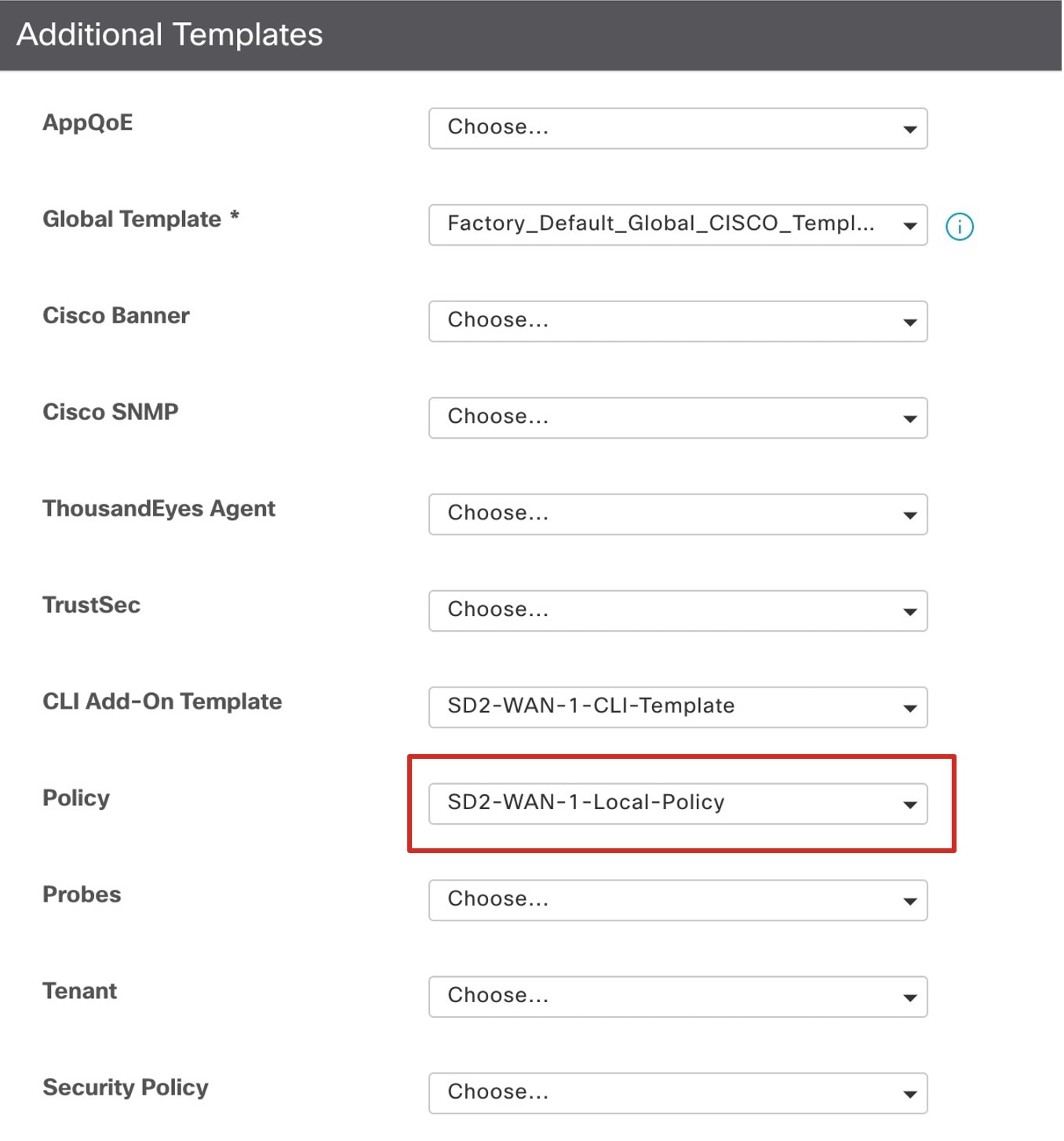
Create a VPN Interface Ethernet template for the firewall outside interface and a BGP template, and apply it to the VPN0 Transport section of the device template.
|
|
Step 2 |
Apply the Localized Data policy and explicit Cisco SD-WAN ACL.
|
Configure NAT64 on Cisco Firepower Appliances
NAT64 works with DNS64 servers to provide IPv6-only clients reachability to the public IPv4 internet. Use the following procedure to configure NAT64 between one inside interface and two outside interfaces on Cisco Firepower appliances using the FMC.
This procedure performs NAT to translate the internal Cisco SD-Access VN1 IPv6 addresses to the outside interface IPv4 address for traffic destined to the DNS64 /96 prefix. In the reverse direction, NAT is applied to translate any IPv4 address from the internet to the DNS64 /96 prefix.
Procedure
|
Step 1 |
Navigate to , and place the Outside-1, Outside-2, and VN1-Inside interfaces into their own interface group. |
|
Step 2 |
Navigate to , and define two network objects for the same inside VN1 IPv6 subnet. This step is required because each object used in auto NAT can only reference one NAT statement. 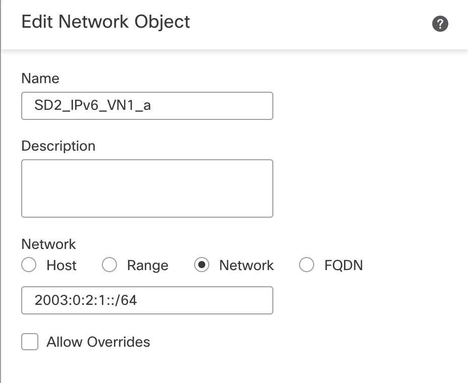  |
|
Step 3 |
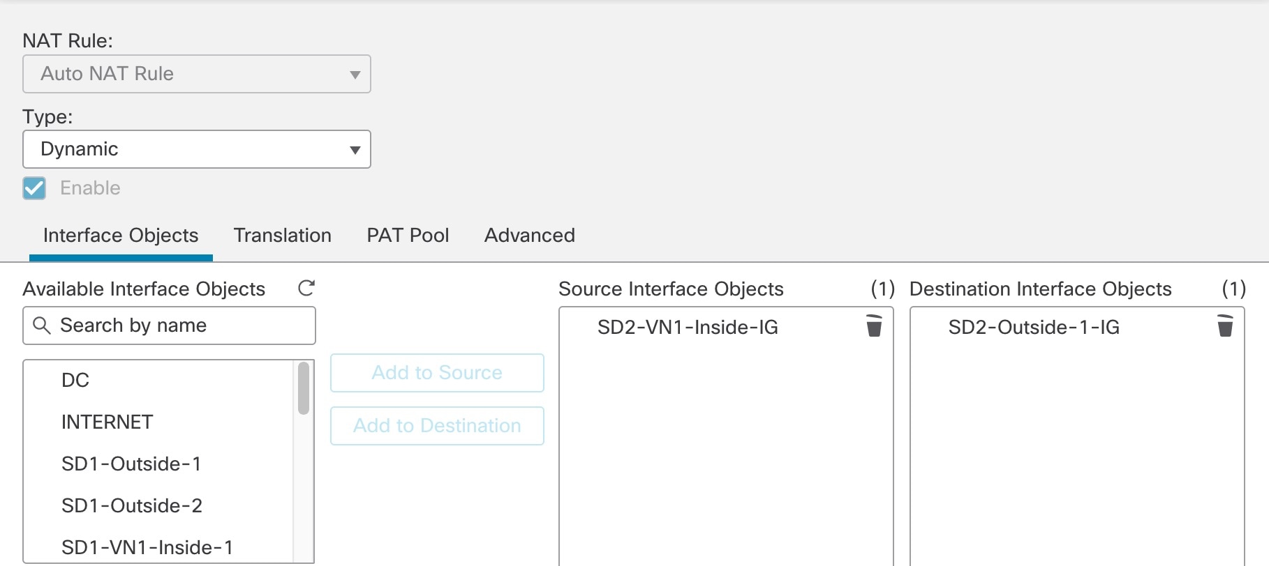
Create an auto NAT dynamic rule to configure NAT for the inside VN1 IPv6 subnet to the Outside-1 interface IP address by doing the following:
|
|
Step 4 |
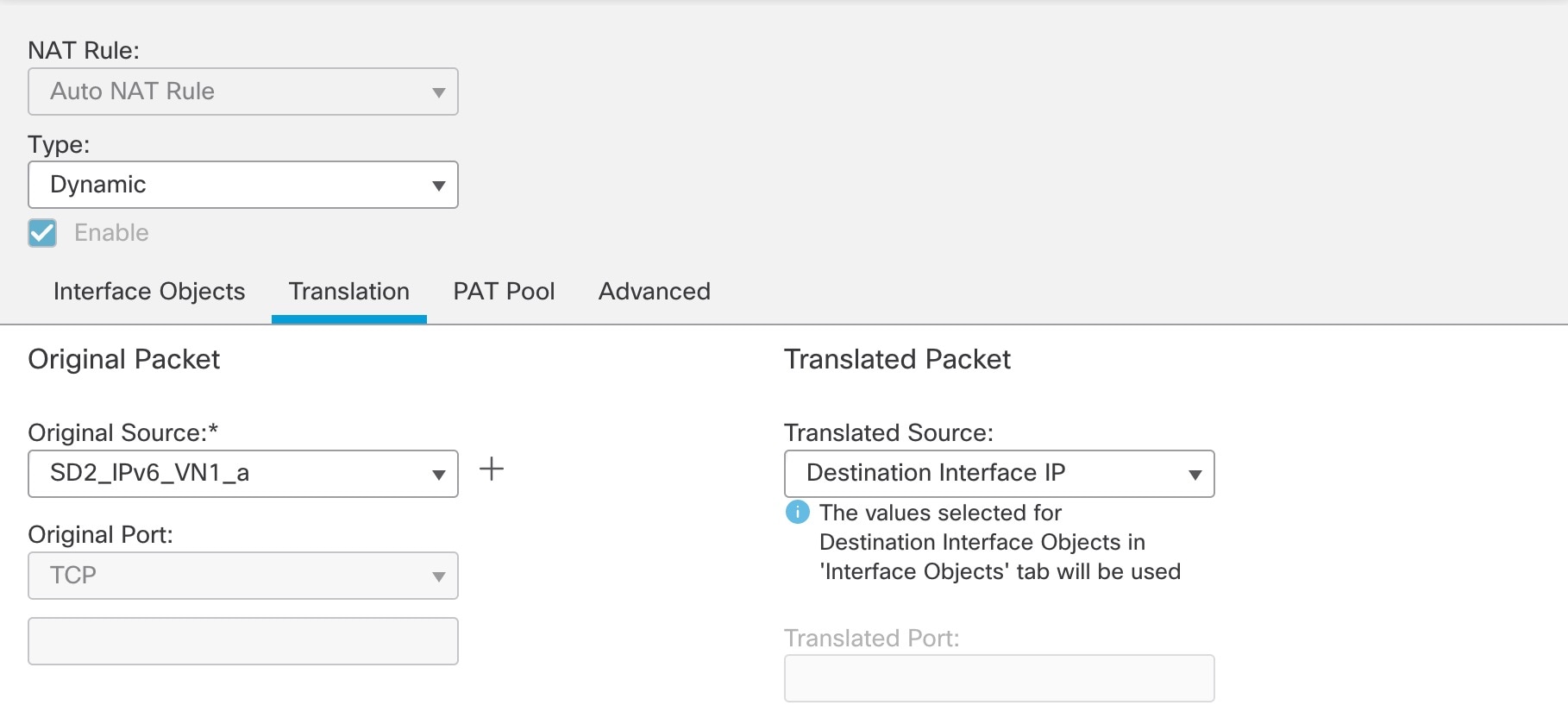
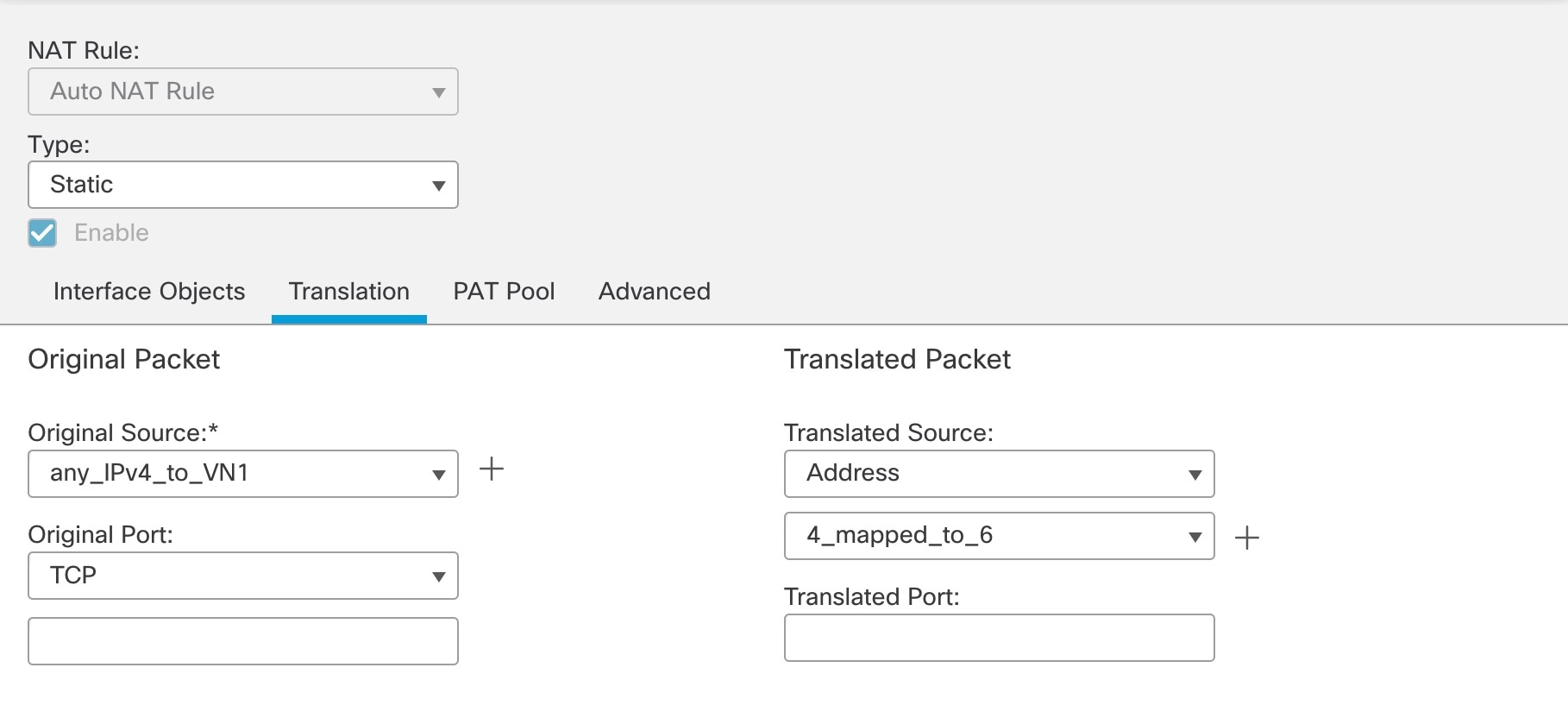
Repeat Step 3 to create a second auto NAT dynamic rule to configure NAT for the inside VN1 IPv6 subnet to the Outside-2 interface IP. However, in the Translation tab, for the original source, use the second network object referencing the same internal IPv6 subnet. 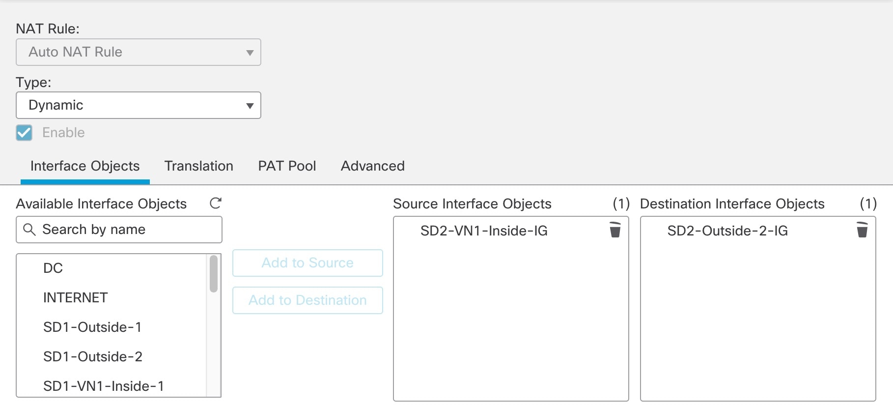 The following image displays the second network object, referencing the same internal IPv6 subnet, as the original source.  |
|
Step 5 |
Define the objects for the NAT64 prefix (2001:6401::/96) and for any IPv4 address (0.0.0.0/0). 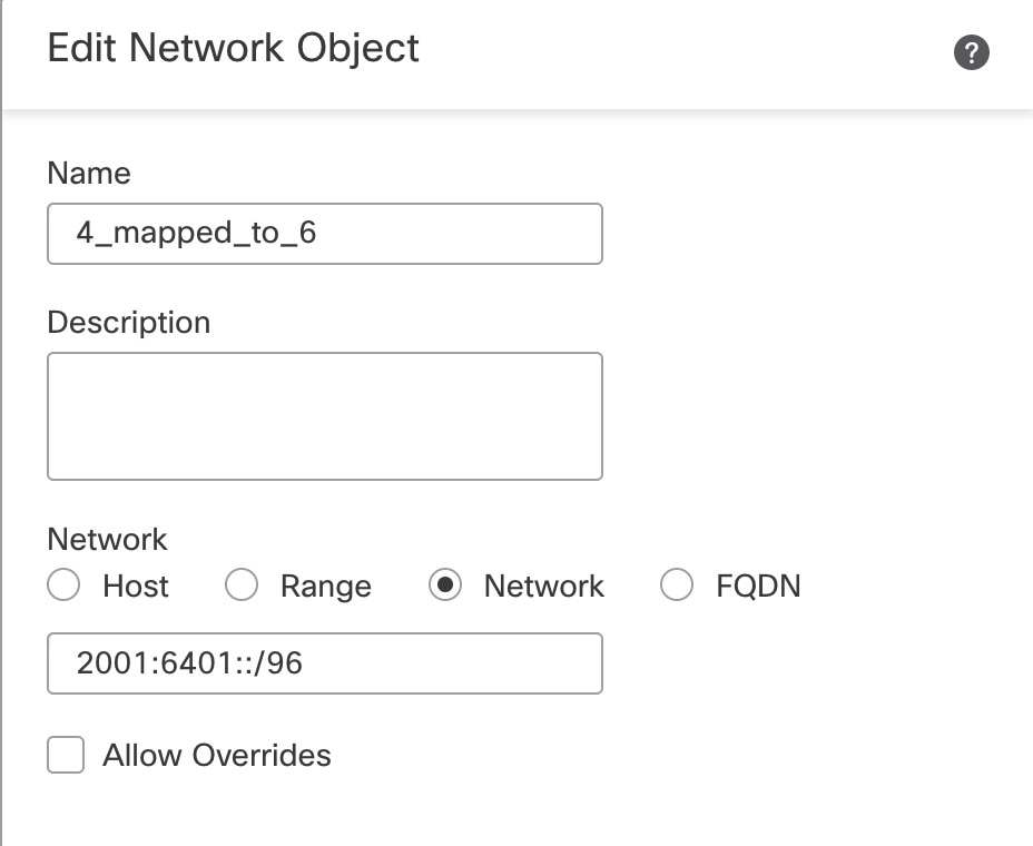 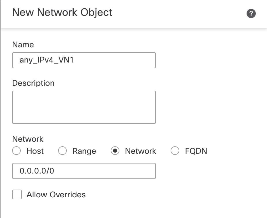 |
|
Step 6 |
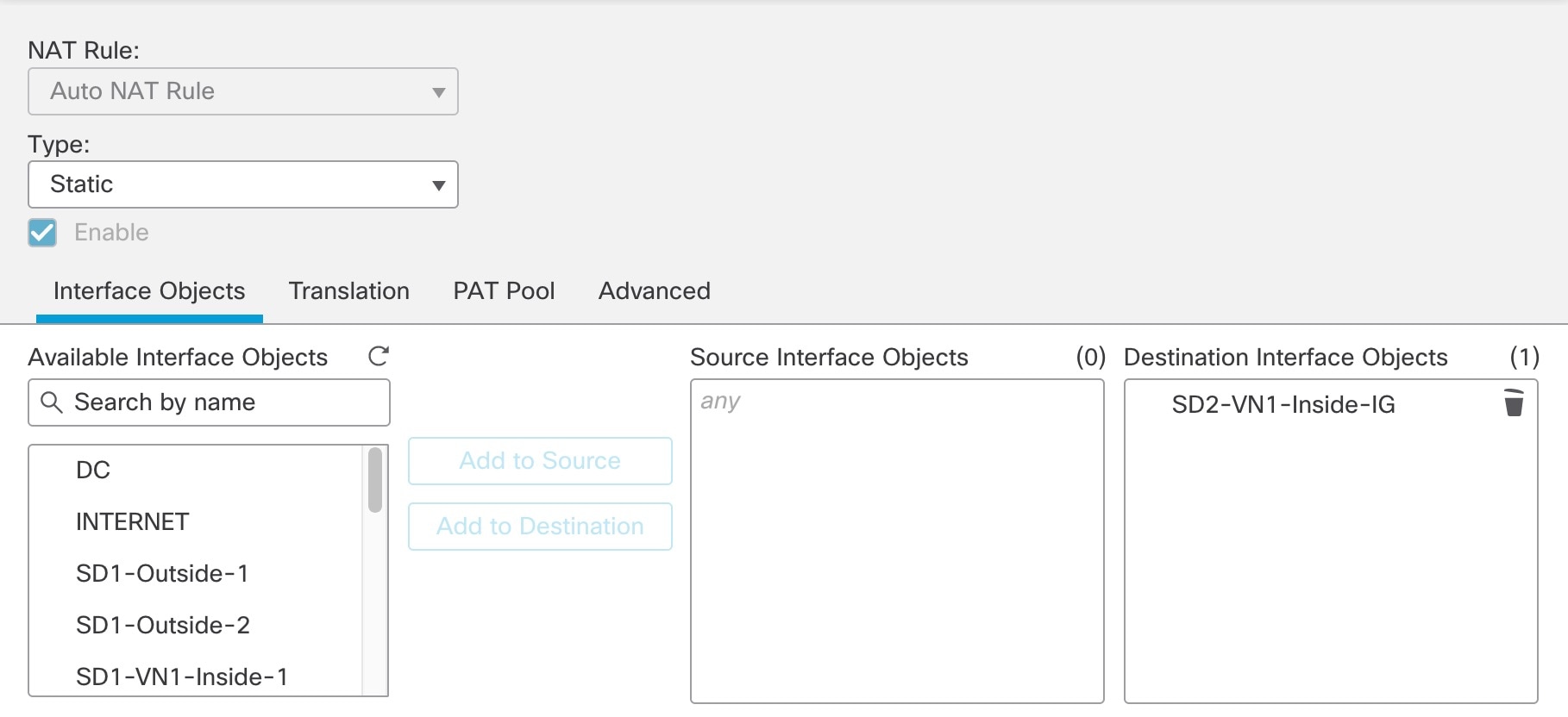
Create an auto NAT static rule to configure NAT for any IPv4 address to the NAT64 prefix by doing the following:
When the configuration is completed, the NAT64 policy is displayed. 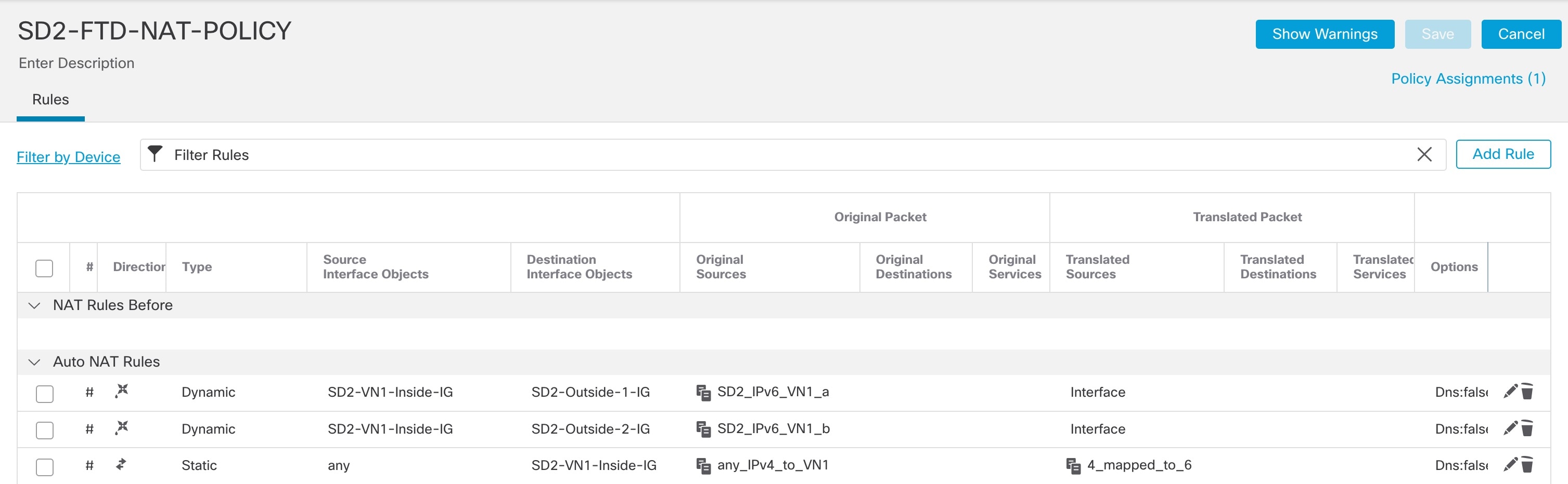 |
Enable SGT Propagation on the Cisco SD-WAN Edge Device
To configure SGT Inline Tagging between the Cisco SD-WAN edge device and Cisco SD-Access fabric borders, use the "Process 2: Configuring Cisco TrustSec Inline Tagging" procedure in the SD-Access SD-WAN Independent Domain Integration Guide. An extra step is required to enable SGT Propagation across Cisco SD-WAN because starting from 20.6.1/17.6.1, SGT Propagation on the Cisco SD-WAN tunnel interface is disabled by default. Ensure that CTS SGT Propagation is enabled on the WAN transport tunnel interfaces as shown in the following procedure.
Procedure
|
Step 1 |
On the Cisco SD-WAN edge device physical interface, enable SGT Inline Tagging. This interface is applied to the VPN0 section of the device template. 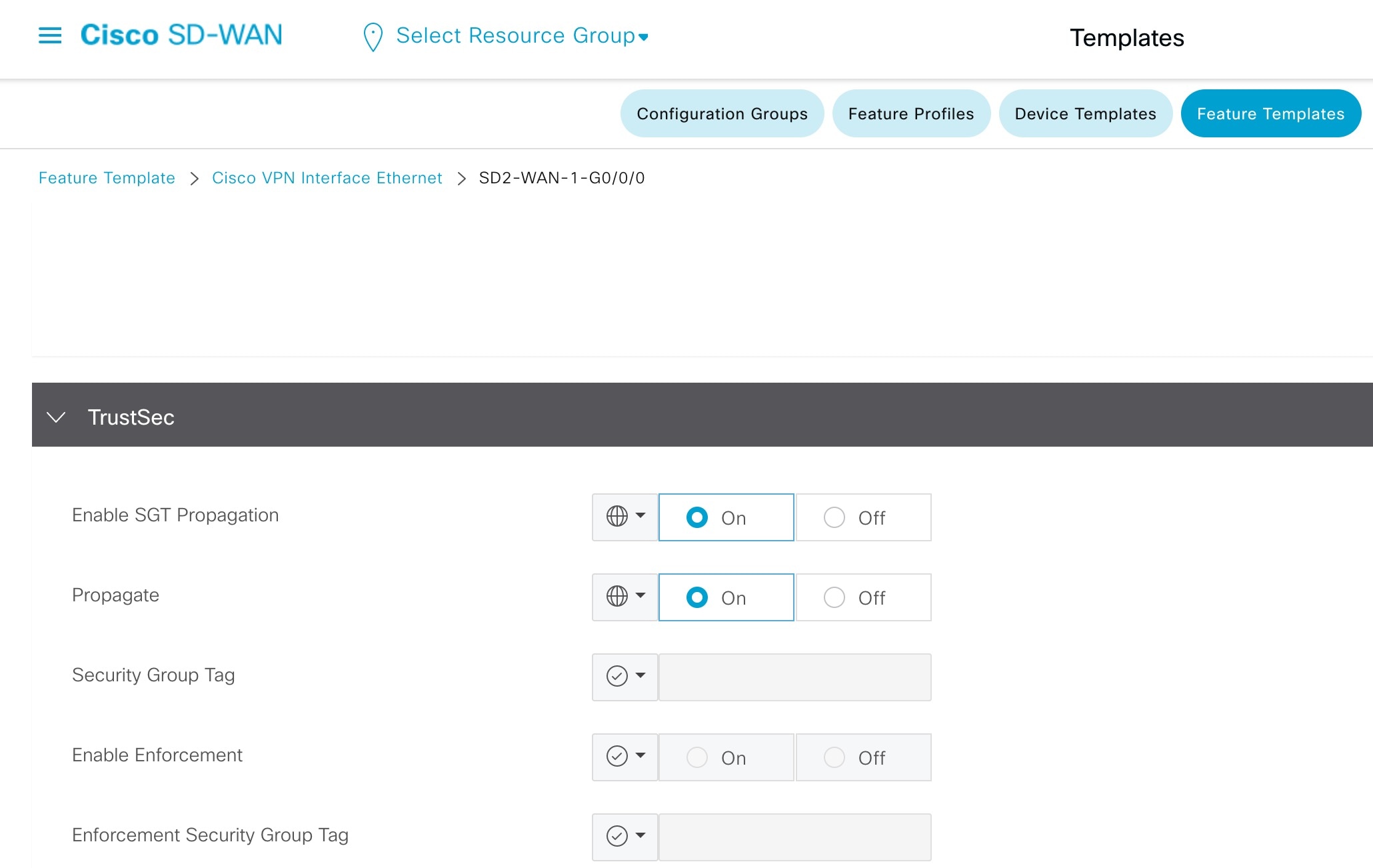 |
|
Step 2 |
On the Cisco SD-WAN edge device service VPN subinterface, enable SGT Inline Tagging. 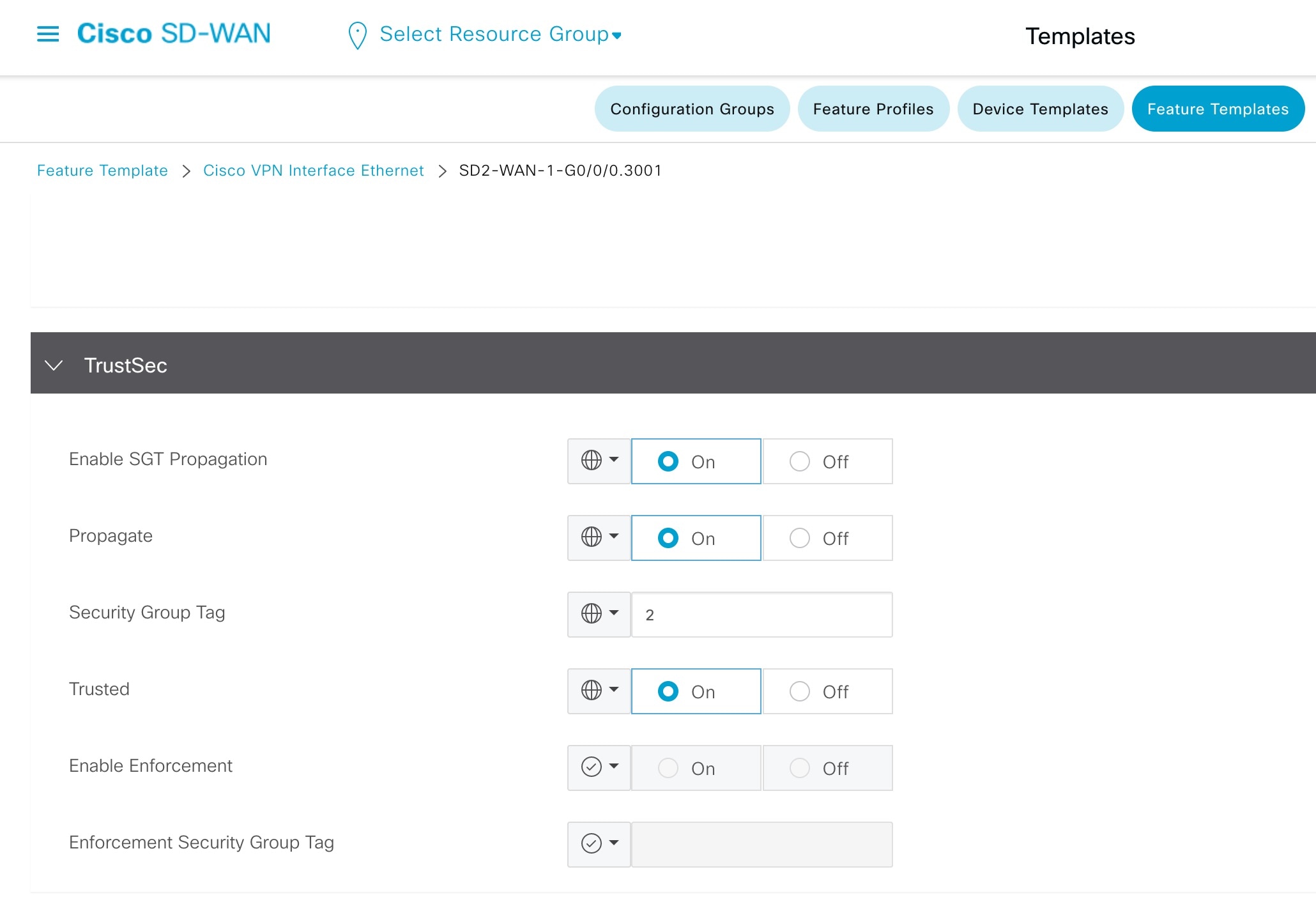 |
|
Step 3 |
On each WAN transport tunnel interface, enable CTS SGT Propagation. 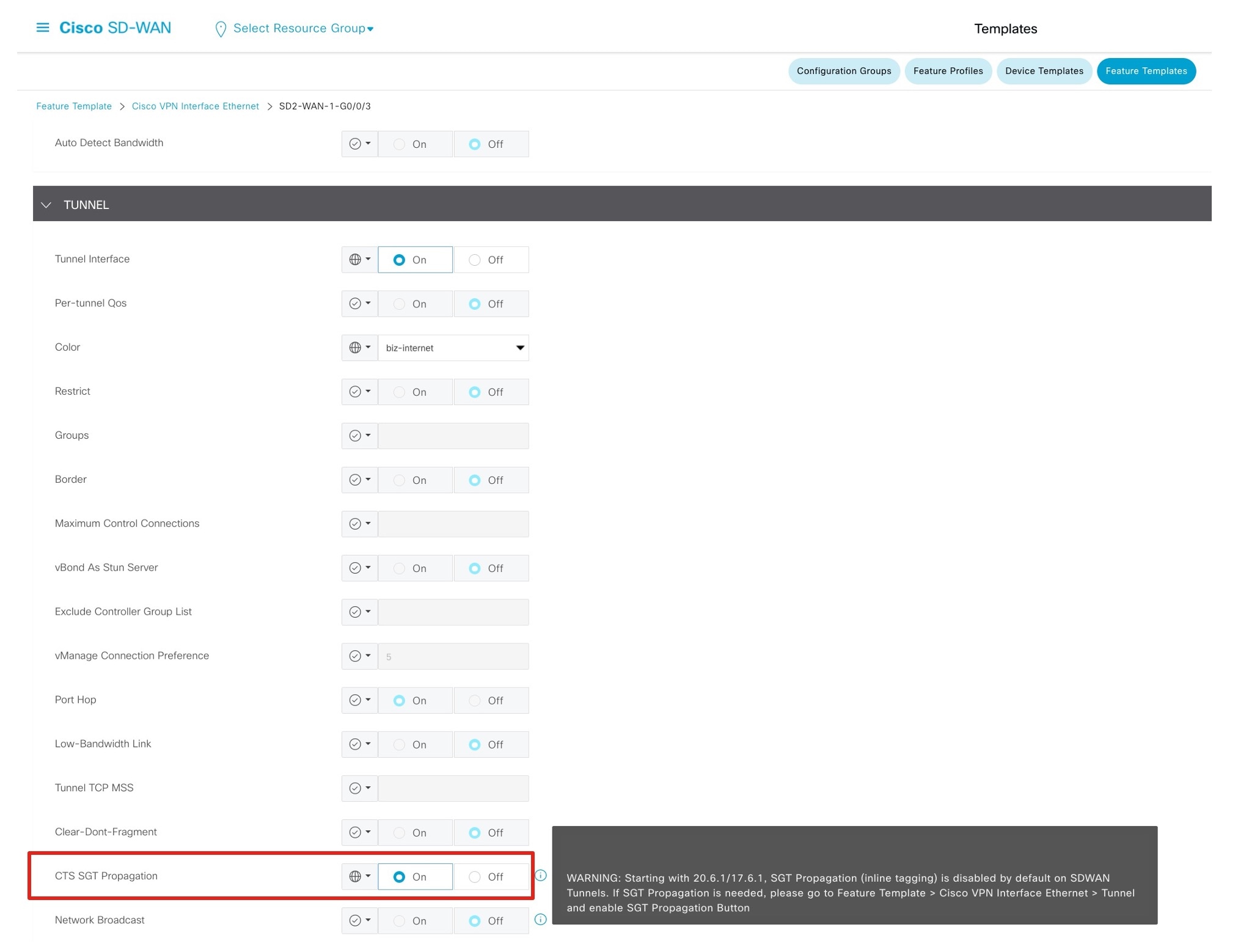 |
Enable ECMP Routing Across Multiple Interfaces
In the following ECMP configuration, both the Outside-1 and Outside-2 interfaces are assigned to the Outside-ECMP zone. Similarly, both the VN1-Inside-1 and VN1-Inside-2 interfaces are assigned to the VN1-ECMP zone.
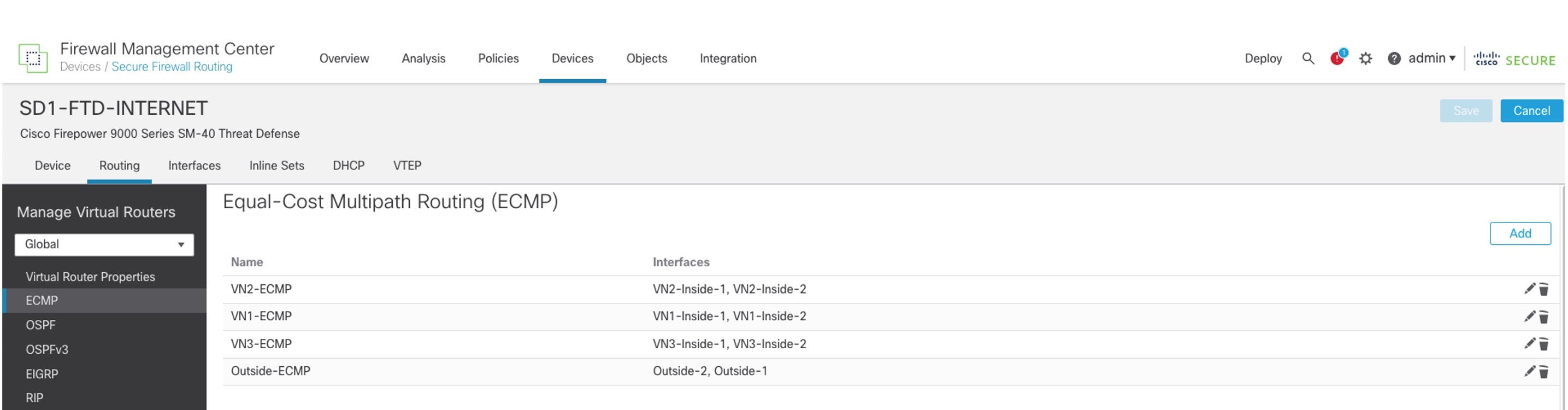
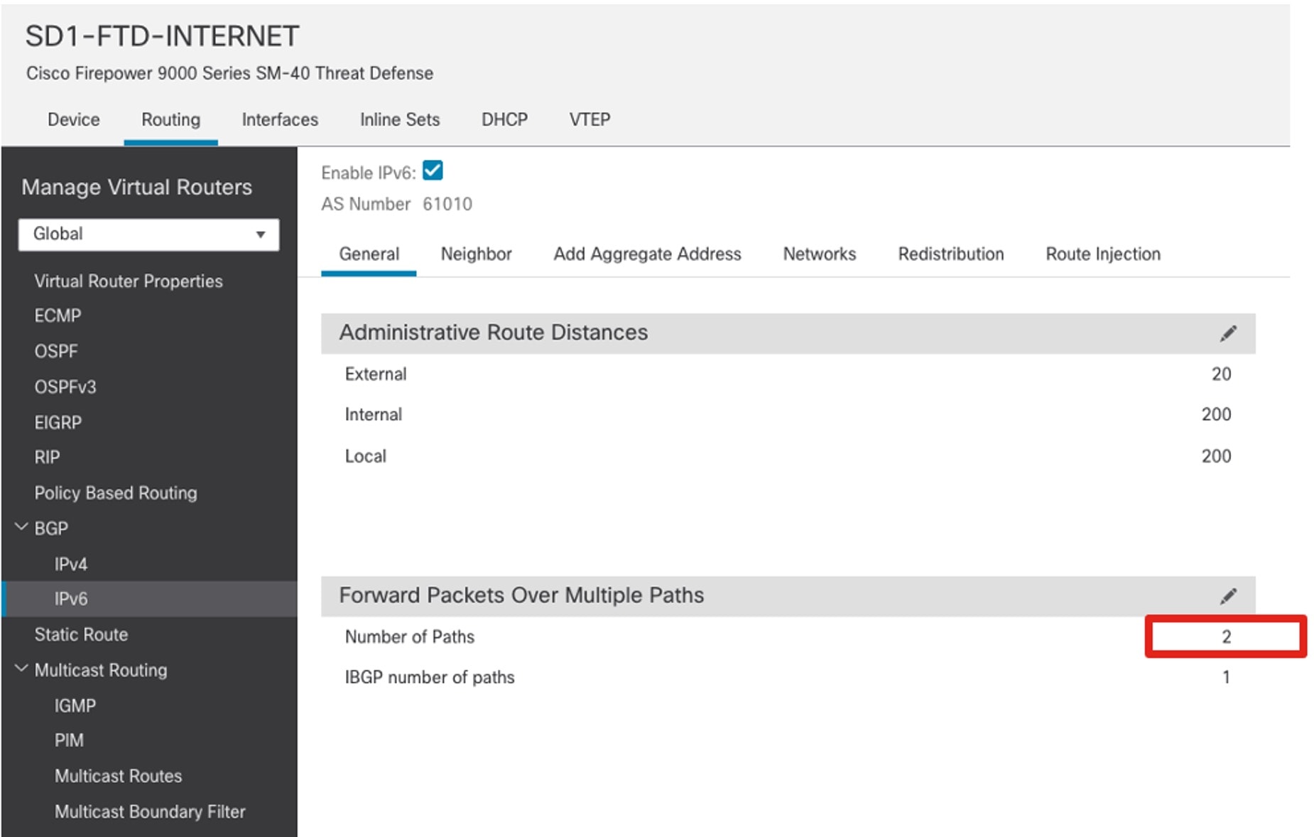
ECMP requires equal-cost paths. To install two equal-cost routes in the routing table, configure the BGP. To do this, go to the BGP general settings and set the number of paths to two.
Layer 3 Handoff Between the Fabric Border and Firewall
When the firewall is configured for Active and Standby High Availability (HA) mode, it can use active and standby IP addresses on each link for monitoring and management purposes. When accounting for the IP address of the fabric border, the number of IP addresses on the link exceeds two. In Catalyst Center, the Layer 3 handoff automation using IP address pool deploys IPv4 /30 and IPv6 /126 masks for the point-to-point links. To accommodate a larger address space, Catalyst Center Release 2.3.4.x and later can deploy custom subnets to each Layer 3 handoff (such as /29 for IPv4 and /125 for IPv6).
Procedure
|
Step 1 |
Configure the fabric border Layer 3 handoff using custom subnets on Catalyst Center. 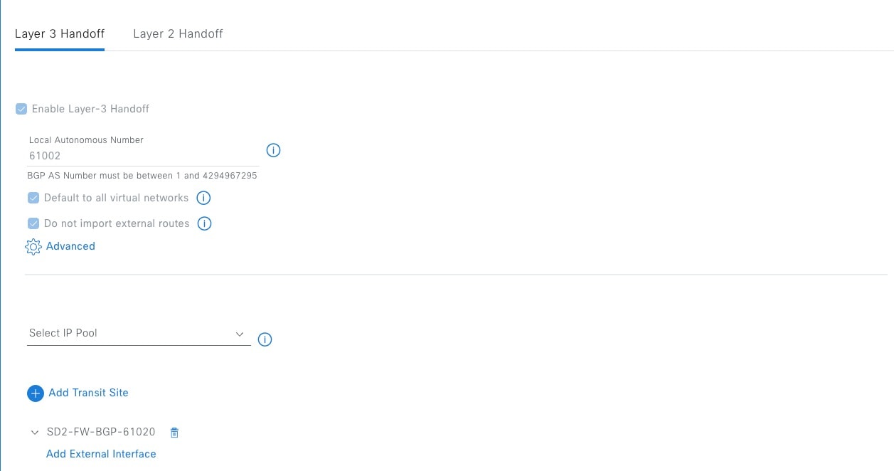 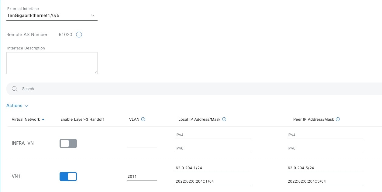 |
|
Step 2 |
Configure the firewall subinterface toward the Cisco SD-Access fabric border VN. 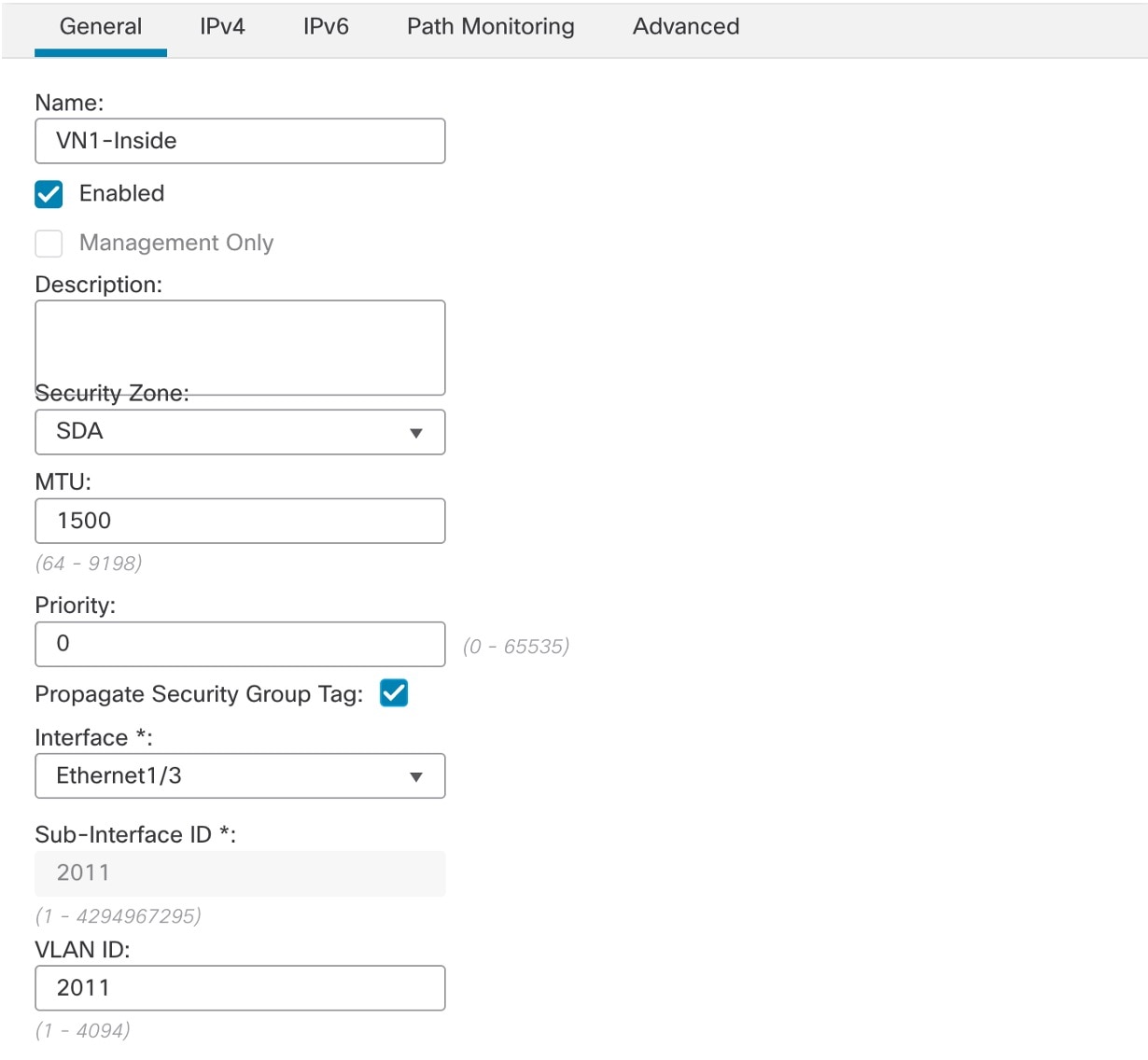 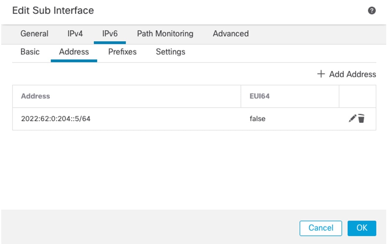 |
|
Step 3 |
On the firewall, configure BGPv6 for the Cisco SD-Access fabric border VN neighbor. 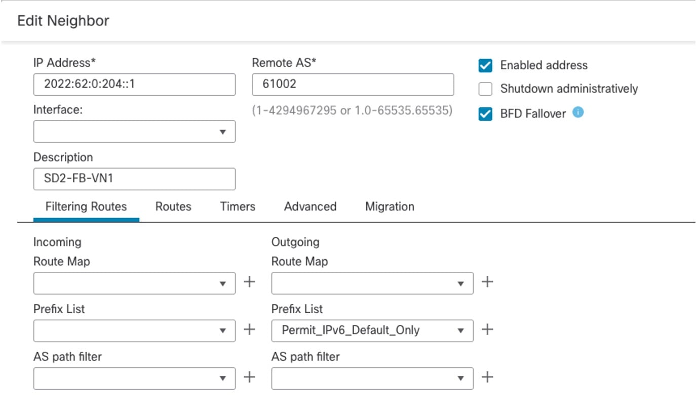 |
Default Route Filter in Branch Sites
Cisco SD-Access fabric border VNs receive default routes from the Internet Firewall. To prevent the branch site from becoming a transit network for internet traffic from remote sites, filter these default routes from being advertised to the Cisco SD-WAN edge device.
In the following example, the fabric border applies a filter to deny the IPv6 default route while permitting all other prefixes out toward the Cisco SD-WAN edge device BGP neighbor.
Cisco SD-Access Fabric Border Configuration
ipv6 prefix-list no-ipv6-default-route seq 5 deny ::/0
ipv6 prefix-list no-ipv6-default-route seq 10 permit ::/0 le 128

router bgp 61002
 address-family ipv6 vrf VN1
  neighbor 2022:62:0:201::12 remote-as 61021
  neighbor 2022:62:0:201::12 update-source Vlan3002
  neighbor 2022:62:0:201::12 fall-over bfd
  neighbor 2022:62:0:201::12 activate
  neighbor 2022:62:0:201::12 weight 65535
  neighbor 2022:62:0:201::12 prefix-list no-ipv6-default-route out
MTU Matching
A Cisco SD-Access switch deployment typically sets the system maximum transmission unit (MTU) to 9100 bytes to accommodate for VXLAN encapsulation. On Layer 3 interfaces, this causes the IPv4 and IPv6 MTU to be 9100 bytes.
Matching the Layer 3 MTU between two connected devices facilitates Path Maximum Transmission Unit Discovery (PMTUD) and avoids one device sending packets larger than the receiving device can handle. In this solution testing, the fabric border Layer 3 IPv4 and IPv6 MTUs on the SVIs connecting to the firewall and Cisco SD-WAN edge devices are adjusted to 1500 bytes.
interface Vlan3001
 description vrf interface to External router
 vrf forwarding VN1
 ip address 61.0.201.129 255.255.255.252
 no ip redirects
 ip mtu 1500
 ip pim sparse-mode
 ip route-cache same-interface
 ipv6 address 2022:61:0:201::1/126
 ipv6 enable
 ipv6 mtu 1500
 ipv6 mld explicit-tracking
 bfd interval 300 min_rx 300 multiplier 3
On the Cisco Firepower appliance, the interface MTU is set to 1500 bytes by default. For Cisco SD-WAN Edges in vManage mode, ip mtu defaults to 1500 bytes whereas ipv6 mtu derives the MTU value from the physical interface MTU default value of 1508 bytes. The ipv6 mtu command is configured through the device CLI or through the Cisco SD-WAN GUI using the Cli Add-On Template.
Cisco SD-WAN Edge Device Configuration
interface GigabitEthernet0/0/0.3001
 encapsulation dot1Q 3001
 vrf forwarding 1
 ip address 62.0.201.142 255.255.255.252
 no ip redirects
 ip mtu 1500
 ipv6 address 2022:62:0:201::E/126
 ipv6 mtu 1500
 no ipv6 redirects
 cts manual
  policy static sgt 2 trusted
 bfd template t1
 arp timeout 1200
IPv6 Multicast
IPv6 multicast in Cisco SD-Access is validated with Any Source Multicast (ASM) for the internal rendezvous point (RP) and external RP in headend replication mode. The following are restrictions to IPv6 multicast in this solution.
-
Currently, Cisco SD-WAN does not support IPv6 multicast.
-
IPv6 multicast is not supported on the Firepower.
| Feature | IPv6 Overlay with IPv4 Underlay |
|---|---|
|
Head-End Replication (Unicast) Underlay |
Yes |
|
Native Multicast Underlay |
No |
|
ASM Overlay (Static RP) |
Yes |
|
SSM Overlay |
Yes |
|
BIDIR Overlay |
No |
|
IP Transit – Multisite |
Yes (headend replication only) |
|
SDA Transit – Multisite |
Yes (headend replication only) |
 Feedback