Wireless Network Configuration Use Case
The following use cases help you understand the wireless network configuration.
The documentation set for this product strives to use bias-free language. For the purposes of this documentation set, bias-free is defined as language that does not imply discrimination based on age, disability, gender, racial identity, ethnic identity, sexual orientation, socioeconomic status, and intersectionality. Exceptions may be present in the documentation due to language that is hardcoded in the user interfaces of the product software, language used based on RFP documentation, or language that is used by a referenced third-party product. Learn more about how Cisco is using Inclusive Language.
The following use cases help you understand the wireless network configuration.
The following topics help you understand the high availability (HA) use cases for wireless networks.
Cisco Wireless Controller HA allows you to use a wireless controller as a backup for a primary wireless controller. The active wireless controller handles all the APs, client traffic, and shares the AP and client database with the standby wireless controller. If there is a failover, the standby wireless controller takes over immediately, resulting in zero client service downtime and zero SSID outage.
Ensure that both the wireless controllers are of the same form factors.
Ensure that both the wireless controllers are running the same software version.
Wireless controller HA supports a maximum redundancy port link latency of 80 ms round-trip time (RTT), minimum bandwidth of 60 Mbps, and minimum maximum transmission unit (MTU) of 1500.
Ensure that you connect the redundancy ports of both the wireless controllers physically or through a Layer 2 virtual network. If you connect redundancy ports through a Layer 2 virtual network, ensure that the link latency, bandwidth, and MTU requirements are met.
For the Cisco Catalyst 9800-CL Wireless Controllers running on ESXi, KVM, and Hyper-V, ensure that the redundancy port connects to the same vswitch.
|
Step 1 |
Ensure that you have the wireless controller in your inventory. For more information, see About Inventory and Add a Network Device. If the wireless controller isn’t available in the inventory, use the Discovery feature to discover it. For more information, see Discover Your Network. |
||
|
Step 2 |
Ensure that both the wireless controllers are in the Managed state in the inventory. For more information, see Display Information About Your Inventory. |
||
|
Step 3 |
Use the show redundancy command to verify that the operating redundancy mode is Non-redundant on both the wireless controllers. |
||
|
Step 4 |
From the top-left corner, click the menu icon and choose . |
||
|
Step 5 |
Check the check box next to the required wireless controller, and then click . |
||
|
Step 6 |
Enter the Redundancy Management IP and the Peer Redundancy Management IP addresses. You must configure the IP addresses used for redundancy management IP and peer redundancy management IP in the same subnet as the management interface of the wireless controller. Ensure that these IP addresses are unused IP addresses within that subnet range. |
||
|
Step 7 |
Enter the Netmask. |
||
|
Step 8 |
From the Select Secondary WLC drop-down list, choose the secondary wireless controller. |
||
|
Step 9 |
Since the Cisco Catalyst 9800-CL Wireless Controller doesn't have a dedicated redundancy port, choose the interface that will be used for the redundancy port.
|
||
|
Step 10 |
Click Configure HA. |
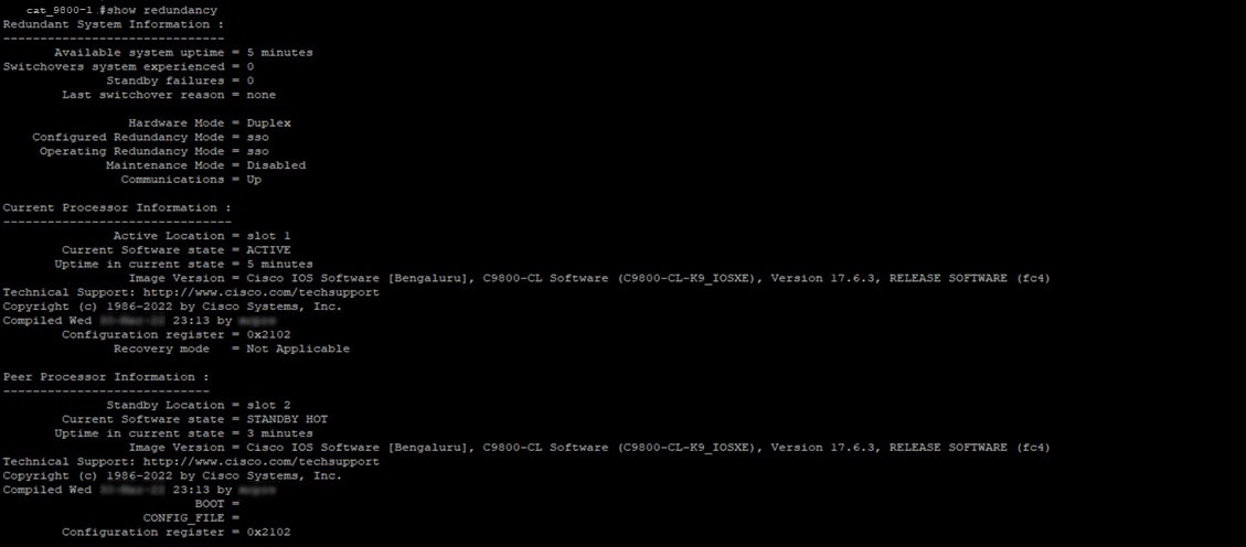
To verify the status of HA, use the show redundancy command. Following is a sample output of this command:
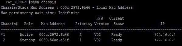
To verify the Priority of the primary wireless controller, use the show chassis command. The Priority of the primary wireless controller is changed to 2 to ensure that its role is Active. Following is a sample output of this command:
Cisco Wireless Controller N+1 HA allows you to use a wireless controller as a backup for multiple primary wireless controllers. Cisco DNA Center doesn't support stateful switchover for N+1 HA and each wireless controller must be managed separately.
 Note |
|
|
Step 1 |
Ensure that you have the wireless controller in your inventory. For more information, see About Inventory and Add a Network Device. If the wireless controller isn’t available in the inventory, use the Discovery feature to discover it. For more information, see Discover Your Network. |
|
Step 2 |
Ensure that both the wireless controllers are in the Managed state in the inventory. For more information, see Display Information About Your Inventory. |
|
Step 3 |
Create enterprise and guest wireless SSIDs. For more information, see Create SSIDs for an Enterprise Wireless Network and Create SSIDs for a Guest Wireless Network. |
|
Step 4 |
If you created a wireless network profile during SSID creation, assign it to the primary wireless controller-managed site. From the top-left corner, click the menu icon and choose , and then click the corresponding Assign Site option for the wireless network profile. |
|
Step 5 |
Provision the primary wireless controller. Choose the role as Active Main WLC. For more information, see Provision a Cisco AireOS Controller and Provision a Cisco Catalyst 9800 Series Wireless Controller. |
|
Step 6 |
Provision the secondary wireless controller. Choose the role as Active Main WLC and choose the secondary managed AP location same as the managed AP location for the primary wireless controller. For more information, see Provision a Cisco AireOS Controller and Provision a Cisco Catalyst 9800 Series Wireless Controller. |
|
Step 7 |
Provision the APs. For more information, see Provision a Cisco AP—Day 1 AP Provisioning. |
The following topics help you understand the mobility configuration use cases for wireless networks.
Two newly added wireless controllers with the same mobility group: The two wireless controllers are newly added to Cisco DNA Center and are not yet provisioned.
Two existing wireless controllers with the same mobility group: The wireless controllers are already added and provisioned on Cisco DNA Center and have the same mobility group name.
Two existing wireless controllers with different mobility group: The wireless controllers are already added and provisioned on Cisco DNA Center and have different mobility group name.
Two existing wireless controllers with a third wireless controller: Adding a new wireless controller to an existing mobility group between two wireless controllers.
Ensure that you have the Cisco Wireless Controllers in your inventory and they are in Managed state. For more information, see About Inventory and Display Information About Your Inventory.
For more information on wireless mobility configuration, see Mobility Configuration Overview.
|
Step 1 |
For newly added wireless controllers with the same mobility group, do the following: |
|
Step 2 |
For two existing wireless controllers with same mobility group, do the following: |
|
Step 3 |
For two existing wireless controllers with different mobility group, do the following: |
|
Step 4 |
For adding a new wireless controller to an existing mobility group between two wireless controllers, do the following: |
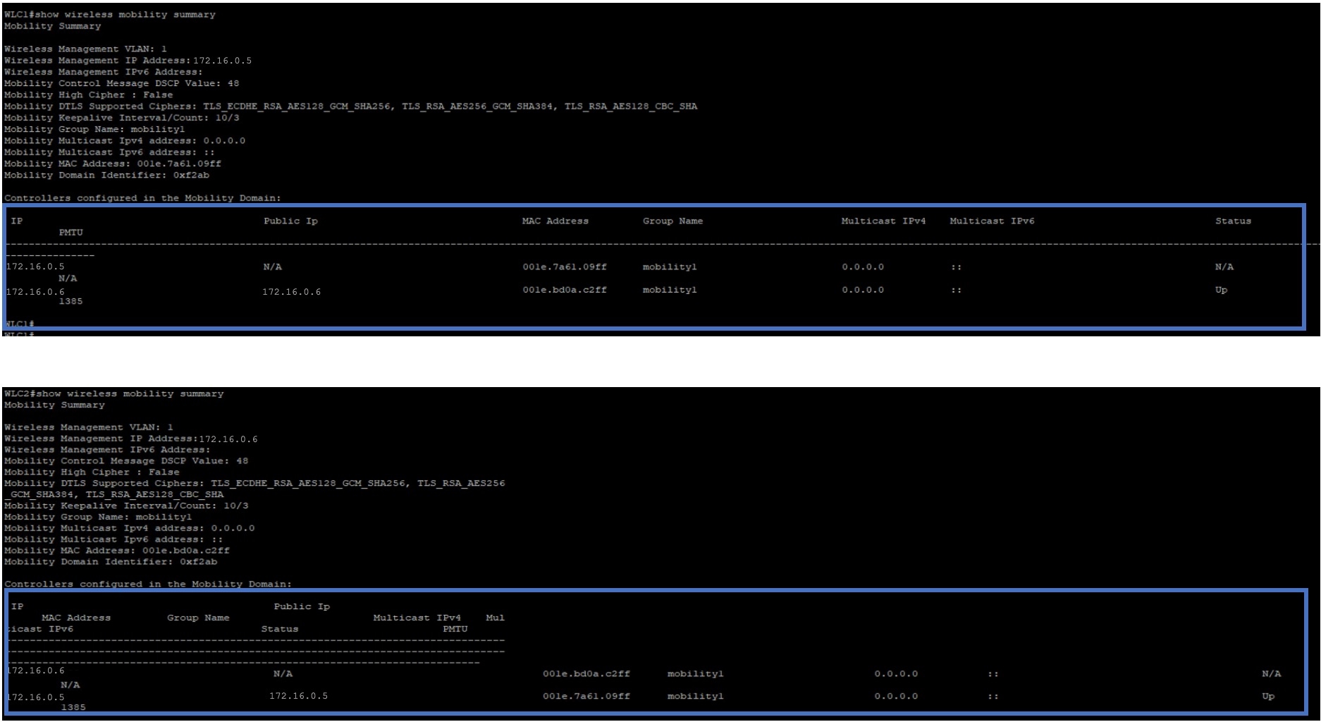
After provisioning, run the show wireless mobility summary command on each of the controllers to verify the mobility tunnel status.
Configuring two newly added wireless controllers - one anchor and one foreign wireless controller.
Configuring three newly added wireless controllers - one anchor and two foreign wireless controllers.
Configuring three newly added wireless controllers - one foreign and two anchor wireless controllers.
Deleting the anchor/foreign setup.
Ensure that you have the Cisco Wireless Controllers in your inventory and they are in Managed state. For more information, see About Inventory and Display Information About Your Inventory.
Use the show wireless mobility summary command to verify that there’s no existing mobility tunnel between the wireless controllers.
|
Step 1 |
Create an SSID for the wireless network and associate it with a new wireless network profile. For more information, see Create SSIDs for an Enterprise Wireless Network or Create SSIDs for a Guest Wireless Network. In the Associate SSID to Profile step, choose the Add Profile option and configure as below:
|
|
Step 2 |
For a scenario with one anchor and one foreign wireless controller, do the following: |
|
Step 3 |
For a scenario with one anchor and two foreign wireless controllers, do the following: |
|
Step 4 |
For a scenario with one foreign and two anchor wireless controllers, do the following: |
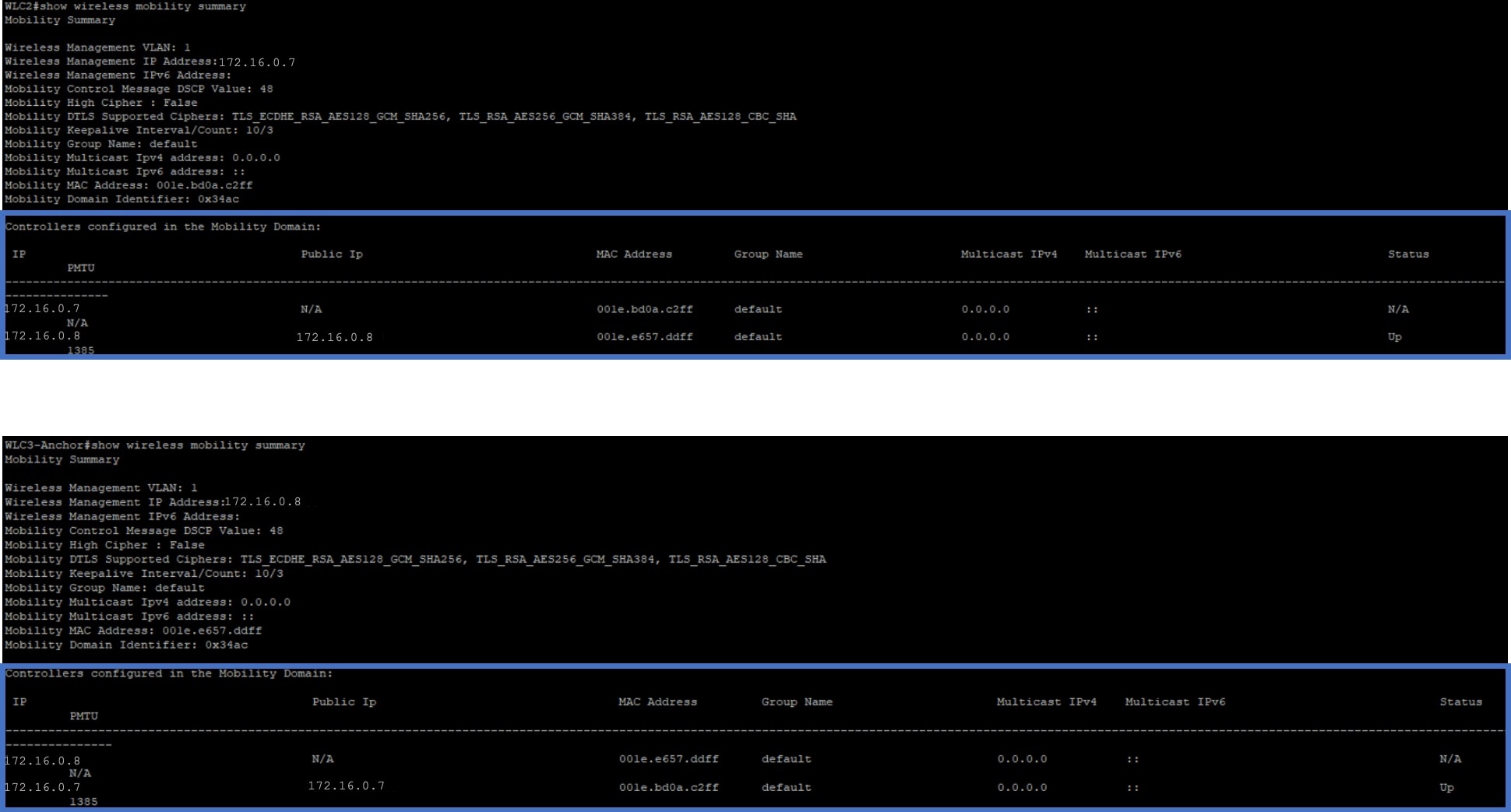
After provisioning, Cisco DNA Center automatically creates a mobility tunnel between the anchor and foreign wireless controllers. Use the show wireless mobility summary command on each of the controllers to verify the mobility tunnel status. Following is a sample output of the command:
Verify the following mobility configurations on the wireless controllers.
Both wireless controllers have the same WLAN and policy profile.
The policy tag is created on foreign wireless controller and mapped to the AP.
The VLAN interface is created for the anchor wireless controller and is mapped to the policy profile.
Delete the anchor/foreign setup
To delete the anchor/foreign setup, do the following:
Ensure that the mobility tunnel between the anchor and foreign wireless controllers is in up state.
Delete the SSID that was created for the wireless network.
From the top-left corner, click the menu icon and choose
Click the Wireless tab.
From the left hierarchy tree, choose Global.
In the SSID table, choose the SSID and click Delete.
Provision the foreign wireless controllers.
In the provision Summary window, ensure that the SSID details are removed.
After provisioning, Cisco DNA Center automatically deletes the mobility tunnel between the anchor and foreign wireless controllers and the WLAN and policy profile is deleted on all the wireless controllers.
The following topics help you understand the AP management use cases for wireless networks.
You can do the following for APs in Cisco DNA Center:
Configure AP-level parameters and radio-level parameters for APs.
Schedule recurring events for APs.
Configure APs using existing templates.
For more information, see AP Configuration in Cisco DNA Center.
You can replace old AP models with new AP models using Cisco DNA Center. You can replace both provisioned and unprovisioned old APs with new ones in Cisco DNA Center. For more information, see AP Refresh Workflow.
Use this procedure to configure the Rest of World (ROW) domain APs.
|
Step 1 |
Create an AP profile with the necessary country code and configure custom site tags. For more information, see Configure Additional Settings for an AP Profile for Cisco IOS XE Devices and Add AP Groups, Flex Groups, Site Tags, and Policy Tags to a Network Profile.
|
||
|
Step 2 |
Add support for the country of operation to the country list on the wireless controller. You must configure at least one site from the country of operation as the managed AP location for the wireless controller. For more information, see Provision a Cisco Catalyst 9800 Series Wireless Controller. |
||
|
Step 3 |
If the wireless controller is not already provisioned with the configurations in Step 1 and Step 2, provision the wireless controller. For more information, see Provision a Cisco Catalyst 9800 Series Wireless Controller. |
||
|
Step 4 |
Configure the AP parameters. For more information, see Configure APs. |
||
|
Step 5 |
Provision the AP. For more information, see Provision a Cisco AP—Day 1 AP Provisioning.
|
To verify the AP configuration, use the show ap summary command. Following is a sample output of this command.
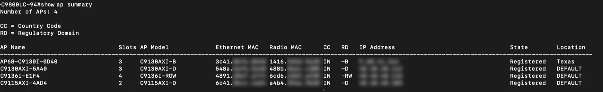
This command displays the country code (CC) and regulatory domain (RD) for the APs. For ROW APs, the regulatory domain is -RW.
Note |
For a ROW AP, if the country code in the command output is --, it indicates that the country code is not available for the AP. The operational status of all the radios for the ROW APs without a country code is down. You must provision the ROW AP to configure the country code for the ROW AP. |
In a Cisco wireless mesh network architecture, APs operate in one of the following ways:
Root APs (RAP): Connected to the wired network.
Mesh APs (MAP): Communicates with other MAPs and RAPs using wireless connections.
The workflow for configuring a wireless mesh network involves the following main steps:
Wireless controller provisioning: Configure a mesh profile, configure the AP authorization list and provision the wireless controller.
AP configuration: Configure AP in bridge mode and deploy.
AP provisioning: Configure the mesh role for AP (RAP or MAP) and provision the AP.
All APs are configured and shipped as MAPs. To use the AP as a RAP, you must reconfigure it as a RAP during AP provisioning. A mesh network must contain at least one RAP. For more information on Cisco Wireless Controller configuration and AP configuration for wireless mesh networks, see About Wireless Mesh Networks.
|
Step 1 |
In the Cisco DNA Center device inventory (), ensure that the wireless controllers and APs are in managed state and assigned to the respective sites. |
|
Step 2 |
Create an AP profile with mesh settings. For more information, see Configure Mesh Settings for an AP Profile for Cisco IOS XE Devices and Configure Mesh Settings for an AP Profile for Cisco AireOS Devices. |
|
Step 3 |
Add the AP Ethernet MAC address to the AP authorization list. For more information, see Create an AP Authorization List. |
|
Step 4 |
Provision the Cisco Wireless Controller. For more information, see Provision a Cisco Catalyst 9800 Series Wireless Controller and Provision a Cisco AireOS Controller. In the provision configuration window, select the AP Authorization List defined in Step 3 and choose the option for authorizing only the mesh access points. |
|
Step 5 |
(Optional) In the Configure Access Points workflow, select the APs and change the AP mode to Bridge/Flex+Bridge mode if they are in Local/Flexconnect mode. For more information, see Configure APs. |
|
Step 6 |
Provision the APs. For more information, see Provision a Cisco AP—Day 1 AP Provisioning.
|
AP Ethernet MAC address: show run | inc username.
AP mesh role (MAP/RAP) after provisioning: show wireless mesh ap summary.
Site tag details: show wireless tag site detailed <site tag name>.
AP profile: show run | section ap profile.
Wireless mesh configurations:
show wireless profile mesh summary
show wireless profile mesh detailed <mesh profile name>
You can replace a faulty access point in the network using the Cisco DNA Center Return Material Authorization (RMA) feature. The RMA workflow lets you replace failed devices quickly, thus improving productivity and reducing operational expense. For wireless APs, the replacement device is assigned to the same site, provisioned with primary wireless controller, RF profile, and AP group settings, and placed on the same floor map location in Cisco DNA Center as the failed AP.
For more information, see Replace a Faulty Access Point.
The following topic helps you understand the migration use case for Cisco Wireless Controllers.
You can migrate from Cisco AireOS Wireless Controller to Cisco Catalyst 9800 Series Wireless Controller using the Learn Device Configurations workflow on Cisco DNA Center. Migration is achieved by using the workflow to learn the device configurations from the wireless controller to be migrated and provisioning the new wireless controller with the learned configurations.
For more information, see Migrate Cisco AireOS Controller to Cisco Catalyst 9800 Series Wireless Controller Using Cisco DNA Center.
 Feedback