Solution Overview
This guide provides an IPv6 solution for deploying a traditional campus network. The solution architecture is based on a three-tier architecture for the Cisco campus, Cisco SD-WAN for WAN, and Cisco Firepower for secure internet connections. The objective is to enable support for IPv6-only clients while keeping the infrastructure in dual stack to also support IPv4 clients during transition.
Technology Overview
The IPv6 solution is a cross-architectural design that encompasses multiple domains, such as campus, data center, firewall, WAN, and internet. The endpoints across the campus sites are IPv6-only clients. Support for IPv4 clients is provided by the dual-stack infrastructure where required.

IPv6 in the Campus Network
The IPv6 solution uses the traditional three-tier architecture of core, distribution, and access layers to provide hierarchy, modularity, and resiliency. Cisco StackWise Virtual Link (SVL) pairs two directly connected switches to form one virtual switch. Cisco SVL is deployed at the distribution, core, and collapsed core layers.
This solution validation uses the IPv6 transport to carry networking protocol communications such as RADIUS, TACACS+, SNMP, NetFlow, CAPWAP, and so on. We avoid using the IPv4 transport for network protocol communications so that all IPv4 configurations can be removed eventually from the network device when legacy IPv4 is removed and IPv6 migration is achieved.
IPv6 in Cisco Software-Defined WAN
Cisco’s SD-WAN architecture consists of separate orchestration, management, control, and data planes. The SD-WAN validator provides automatic onboarding of SD-WAN routers into the SD-WAN overlay. The SD-WAN manager is responsible for central configuration and monitoring. The SD-WAN controller is responsible for the centralized control plane of the SD-WAN network. The SD-WAN edge establishes secure data-plane connectivity with other SD-WAN edges. Overlay IPv6 traffic can be transported in IPsec tunnels established over IPv4 or IPv6 transports based on local and remote SD-WAN edge configurations. With the IPv6 Strict Control feature, the IPv6 transport is preferred for data and control plane on dual-stack interfaces.
The main campus site and branch campus sites are connected across the SD-WAN fabric. Data plane, control plane, and policy plane integration is achieved using eBGP, VRF-lite, and inline SGT between devices.
IPv6 on Cisco Firepower
Cisco Firepower provides dual-stack IPv4 and IPv6 support. Network segmentation for data plane and control plane is accomplished by using either firewall instances or firewall virtual routers. The firewall performs network address translation services to support IPv6-only clients communicating with IPv4 servers. In addition, the firewall provides traffic filtering between the sites, data center, and internet.
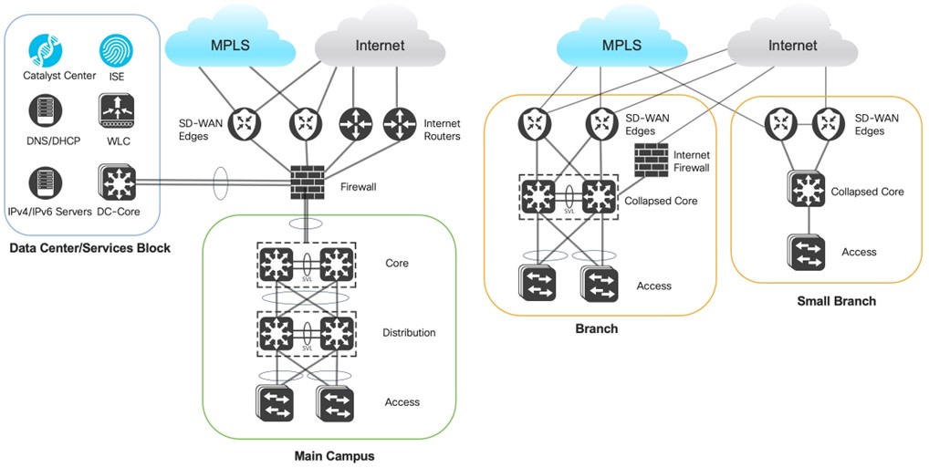
The logical topology of the solution test bed represents the reference customer network design with multiple campus sites of various sizes. The SD-WAN fabric connects multiple campus sites and the data center for IPv4 and IPv6 traffic communication. The campus and branch sites are implemented with redundancy wherever possible, including uplink redundancy and node redundancy. The product family for the solution is Catalyst switches and routers. The campus deploys Catalyst 9000 switches and Catalyst 9800 Wireless Controllers. The SD-WAN edge routers are Catalyst 8000s.
The Firepower security appliances at each site implement security requirements for internal and internet traffic. The Firepower enables NAT64 translation that works with DNS64 to provide IPv6-only clients with reachability to IPv4 servers. Firepower appliances are centrally managed by Firepower Management Center (FMC).
The data center in the architecture contains services such as DNS, DHCP, and other applications. Cisco Catalyst Center, wireless controllers, Cisco ISE, and Cisco FMC are deployed in the data center collocated with the main site campus. In this solution, Catalyst Center is deployed in IPv6 mode and is used for assurance and software image management capabilities. In IPv6 mode, Catalyst Center does not offer configuration management; device configurations are applied manually.
Main Campus Design Overview
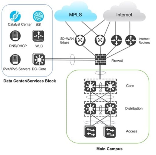
Data Center Shared Services Block
The data center shared services block is collocated with the main campus site. The data center block provides critical services used by network and user devices. Devices in the data center include Catalyst Center in IPv6 mode, Cisco ISE, wireless controllers, DNS, DHCP servers, and other IPv4 and IPv6 servers.
IPv6 is the preferred transport for network protocol communications, such as RADIUS, TACACS+, SNMP, NetFlow, and CAPWAP. Network protocol traffic is transmitted via IPv6 transport within global routing. Because the data center block also contains services for user VRFs, it must be reachable in the VRF routing tables. This reachability is accomplished by performing route leaking between global and VRF on the firewall.
One critical component in the data center is Cisco ISE, which is responsible for providing RADIUS and TACACS+ services for authentication and authorization. With Cisco ISE 3.3, support for the IPv6 Guest Portal is integrated to enable Central Web Authentication for IPv6 wireless guest services. Cisco ISE offers Dot1x and MAB authentication services for wired and wireless connections. Cisco ISE stores the Cisco TrustSec policy to permit or deny traffic based on SGT values within the Cisco TrustSec domain.
Main Campus
The main campus is deployed with the traditional three-tier architecture of core, distribution, and access layers. This architecture provides a hierarchical, modular, and resilient network framework.
The core and distribution switches are deployed using SVL technology, where two physical switches combine to form one logical switch. This facilitates the creation of multichassis Ether-channel, eliminating the need for spanning-tree blocked ports when extending the VLANs across different access switches. Additionally, the requirement to use a first hop redundancy protocol like HSRP is removed, because a single logical switch handles the gateway function.
A multi-VRF environment is deployed to maintain macrosegmentation. VRF-lite extends the VRFs hop-by-hop from distribution to core, firewall, and SD-WAN edges.
IPv6 global routing serves as the backbone for network protocol communications, consisting of services like RADIUS, TACACS, SNMP, CAPWAP, and NetFlow. OSFPv3 is enabled between the core and distribution layers within the global routing table and the VRF routing table and subsequently redistributed into BGP on the core switch. The core switch establishes eBGP sessions with Cisco Firepower in global and VRF routing to ensure reachability to external networks.
The distribution-layer switch offers gateway services for user traffic and AP traffic to the wireless controller. The switch virtual interface (SVI) can be configured to support SLAAC only, stateless DHCPv6, or stateful DHCPv6 to manage the client IPv6 address assignment.
The access-layer switches connect clients to the network. Several configurations are enabled at the access layer:
-
Enable Dot1x globally and configure Dot1x authentication, network authorization, and accounting method lists to point to the Cisco ISE RADIUS server.
-
Send SNMP trap MAC update notifications to Cisco ISE for profiling.
-
Enable device tracking to build a binding table based on ICMPv6 ND. This is required by other features like Dot1x, MAB, web authentication, CTS, and certain IPv6 first hop security features.
-
Apply Identity-Based Networking Services (IBNS 2.0) closed authentication templates on access ports to enable Dot1x and fallback to MAB authentication.
-
Enable CTS enforcement on user VLANs.
-
Enable IPv6 first hop security features, such as IPv6 DHCP Guard and RA Guard.
For access switch configuration examples, see the Cisco ISE Secure Wired Access Prescription Deployment Guide.
Cisco Firepower
The main campus site design uses the Cisco Firepower 9300 to secure IPv6 traffic. The design enables macrosegmentation between campus VRFs and enables access to shared resources in the data center and to the internet. BGP is the preferred routing protocol to facilitate prefix reachability exchange between SD-WAN edge routers, firewall, and the campus core switch. The BGP protocol offers fast convergence with BFD, granular prefix filtering, and BGP attributes for influencing the best path selection. BGP facilitates route leaking between global and VRF on the Cisco Firepower where BGP prefixes learned from global routing are imported into the VRFs.
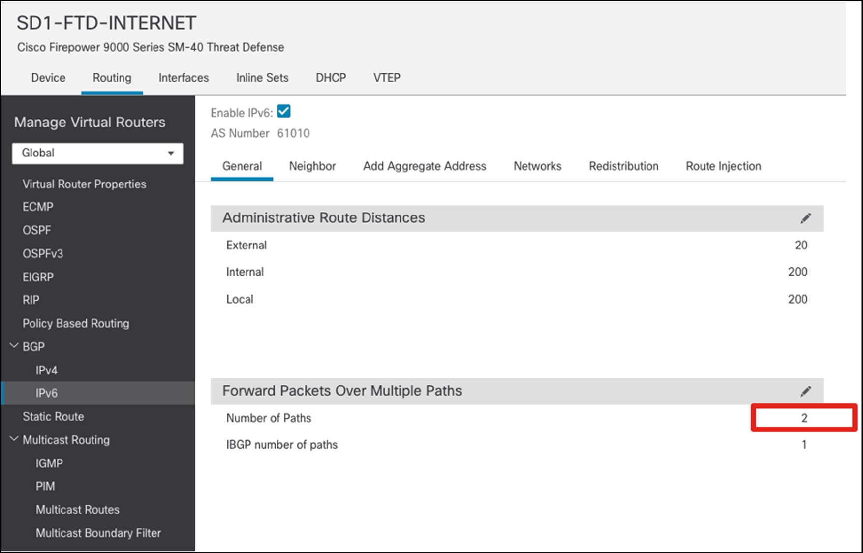
Stateful inspection on the firewall requires that a return packet must arrive on the same interface as the original packet. Because there are two external firewall interfaces connected to SD-WAN edges, return packets arriving on a different interface are dropped by the firewall. To use redundant firewall links, ECMP zones are deployed to enable ECMP routing and load balancing of traffic across multiple interfaces. In this solution testing, the two external firewall interfaces connected to SD-WAN edges are placed in an ECMP zone. Additionally, the eBGP multipath is set to 2 on the Firepower BGP settings to enable two equal cost paths to the destination.
From a routing policy perspective, it’s important to block the default route on the firewall from being advertised to the SD-WAN edges to prevent the main campus site from becoming a transit network for internet traffic coming from remote branch sites. However, if the main site provides a backup internet connection to branch sites, the default route isn't blocked; instead, it's advertised with a higher metric.
Another function of the firewall is to perform network address translation services. NAT44 can be deployed to enable IPv4 private hosts to communicate with the public IPv4 internet. NAT64 can be deployed to allow IPv6-only hosts access to IPv4 servers in the data center and the internet.
Cisco Firepower is configured as a remote access server for Cisco Secure Client connecting from the IPv4 or IPv6 internet. To support Cisco Secure Client, the firewall outside interface must be placed in the global virtual router. Upon successful authentication and authorization, Cisco Secure Client obtains an IPv6 address on its virtual adapter and can access IPv6 resources behind Cisco Firepower. For Cisco Secure Client to access resources behind a VRF on the firewall, static route leaking between global and VRF is performed for the IPv6 client pool prefix.
Wireless Network
The Catalyst 9800 wireless controller resides in the data center and manages the APs in the main campus and branch sites using the IPv6 transport. In this solution, the APs obtain an IPv6 address via DHCPv6. From DHCPv6 option 53, the APs learn the wireless controller IPv6 address to establish the CAPWAP tunnel. The APs provide WLAN services for enterprise and guest users at the main campus and branch sites.

Control Plane and Data Plane Integration
The firewall is logically placed between the campus core switch and the SD-WAN edges to connect the campus VRF to the SD-WAN VPN, enabling the same VRF communication across different sites. In this location, the firewall can apply security policies to permit or deny traffic between same VRF hosts located in different sites across SD-WAN. It also secures traffic to the shared services network in the data center and the internet.
The Cisco Firepower device supports using virtual routers to maintain separate routing tables. By default, a global virtual router routes traffic using the global routing table. The global virtual router is used to transport network device communication traffic like RADIUS and CAPWAP. The user-defined virtual router connects to the campus VRF and SD-WAN service VPN to carry user traffic.
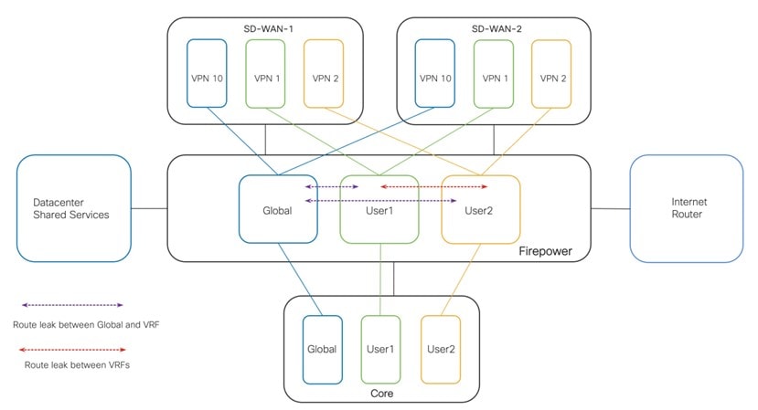
To create a one-to-one mapping between the campus VRF and SD-WAN service VPN, one firewall virtual router subinterface connects to the core switch VRF interface. Another firewall virtual router subinterface connects to the SD-WAN edge service-facing interface. The firewall virtual router establishes BGP peering sessions to the campus core switch and SD-WAN edges to exchange routes between the campus VRF and the SD-WAN service VPN. The SD-WAN edge performs mutual BGP-to-OMP route redistribution for the service VPN to receive and propagate prefix reachability information with the SD-WAN fabric. This setup maintains end-to-end control plane and data plane integration across sites.
Policy Plane Integration
To extend the Cisco TrustSec domain from the main campus to branch sites, SGT inline tagging is enabled on the interfaces between the SD-WAN edge, firewall, and core, distribution, and access switches. With SGT inline tagging enabled, the interface supports the Cisco Ethertype 0x8908 frame format with the CMD header. In addition, SGT propagation is enabled on the SD-WAN tunnel interfaces. SGT is placed in the CMD field of the Ethernet header by the main site access switch and sent hop by hop to the firewall. The firewall sends the frame to the SD-WAN edge, where the SGT is copied from the Ethernet CMD field to the IPsec CMD field and carried across the SD-WAN fabric. On the receiving branch SD-WAN edge, the SGT is transferred from the IPsec CMD field to the Ethernet CMD field. This Ethernet frame is sent to the core switch and forwarded to the remote site access switch, where it can perform egress policy enforcement. This setup maintains end-to-end policy plane integration across sites.

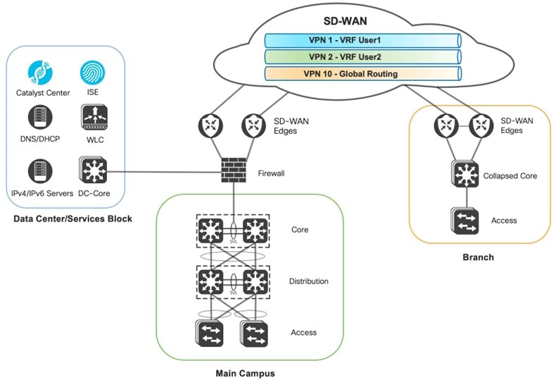
Global and VRF Routing Across SD-WAN
Catalyst Center is in the data center collocated with the main campus site. Communication is required between Catalyst Center and switches located at remote sites across SD-WAN for device discovery, software management, and assurance. The wireless controller in the data center requires reachability to the APs at remote branch locations to form CAPWAPv6 tunnels. Cisco ISE also needs to reach the network access devices to provide the AAA services. For this purpose, a dedicated service VPN (that is, VPN 10) is used to enable global routing across the SD-WAN fabric. The firewall global virtual router interface connects to this SD-WAN service VPN interface to enable communication between the shared services devices and the remote branch network devices across SD-WAN. Another firewall global virtual router interface connects to the main site core switch global interface to enable reachability to the switches and APs in the main site.
Campus VRFs are mapped to other VPNs to carry user traffic. The following diagram shows VPN 1 mapped to Campus VRF User1, VPN 2 mapped to Campus VRF User2, and VPN 10 mapped to global routing.
Branch Site Design Overview
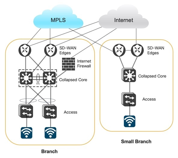
The branch site design deploys Cisco Firepower strictly as the internet firewall. The collapsed core connects to two SD-WAN edges to enable communication to the main campus site, branch sites, and the shared services block in the data center.
The collapsed core provides gateway services to the access layer. The VRF interface connects to the firewall (inside) subinterface. eBGP peering is formed between the firewall and the core switch VRF interface. The campus VRF receives the default IPv4 and IPv6 routes to allow the VRF access to the internet. The collapsed core also has VRF interfaces that connect to the corresponding SD-WAN edge service-facing interfaces. It forms eBGP peering with the SD-WAN edges to advertise local VRF routes and receive specific routes to remote networks in the same VRF and to the shared services network in the data center. To prevent the branch site from becoming a transit site for internet traffic from other sites, the collapsed core filters BGP default routes to the SD-WAN edges.
Because all VRF routes converge in the global routing table of the firewall and each VRF has a default route towards the internet firewall, traffic can be routed between different VRFs. Access policies should be in place to deny traffic between different VRFs, unless inter-VRF traffic is desired.
The wireless controller at the data center shared services manages the branch APs. The APs are placed in FlexConnect mode to provide central and local switching options to enterprise and guest WLANs.
The small branch site also deploys the collapsed core switch model. Instead of going through a dedicated firewall to access the internet, it uses the SD-WAN direct internet access functions using NAT, NAT64, and NAT66. TLOC Extension over IPv6 is deployed between the SD-WAN edges to allow WAN transport redundancy when each SD-WAN edge connects to only one WAN transport. The SD-WAN zone-based firewall and intrusion prevention system (FIPS) is deployed at the branch site to provide security.
Hardware and Software Specifications
The solution is validated with the hardware and software listed in this table. For the complete list of hardware supported, see the Cisco Software-Defined Access Compatibility Matrix.
| Role | Hardware Platform | Software Release | |
|---|---|---|---|
|
Catalyst Center Controller |
DN2-HW-APL |
2.3.7.7 |
2.3.7.9 |
|
Cisco Identity Service Management, RADIUS Server |
Virtual (ISE-VM-K9) platform |
3.3 Patch 4 |
3.3 Patch 4 |
|
Cisco SD-WAN NMS Controller |
vManage |
20.12 |
20.12.5 |
|
Cisco SD-WAN Edge |
C8300, C8500 |
17.12.4a |
17.12.5a |
|
Cisco Core Switch |
C9500H, C9600 |
17.9.5, 17.12.4 |
17.9.6a, 17.12.5 |
|
Cisco Distribution Switch |
C9500H, C9600 |
17.9.5, 17.12.4 |
17.9.6a, 17.12.5 |
|
Cisco Access Switch |
C9200, C9300, C9400 |
17.9.5, 17.12.4 |
17.9.6a, 17.12.5 |
|
Cisco Wireless Controller |
C9800-40, C9800-CL |
17.9.6, 17.12.4 |
17.9.6a, 17.12.5 |
|
Cisco Firepower Threat Defense Security Appliance |
FPR9300, FPR2110 |
7.2 |
7.2 |
|
Cisco Secure Firewall Management Center |
FMC Virtual |
7.2 |
7.2 |
Scale
The solution test verified the scale numbers listed in the following table. For the software and hardware capacity, see the Cisco Catalyst Center Data Sheet.
| Category | Value |
|---|---|
|
Number of VRFs per site |
5 |
|
Number of wireless controllers per site |
2 per HA |
|
Number of APs per site |
200 – 1000 |
|
Number of IPv6 endpoints |
20,000 |
|
Number of SSIDs per site |
4 |
|
Number of SGTs |
100 |
|
Traffic profile |
Unicast and multicast |
Solution Use Cases
The following use cases were validated on the Cisco traditional campus, Cisco SD-WAN, and Firepower IPv6 profile.
-
Automated secure Cisco SD-WAN transporting IPv4 and IPv6 traffic
-
Wireless deployment for IPv6 enterprise users
-
Network visibility, monitoring, and troubleshooting for IPv6 devices and endpoints
-
IPv6 application visibility and health
-
Network robustness for IPv6 networks
-
Secure onboarding of IPv6-only endpoints of different types
-
End-to-end IPv6 traffic and secure internet access
-
End-to-end inline SGT traffic enforcement between SD-WAN sites
-
IPv6-only client access of IPv6 applications and legacy IPv4 applications
-
IPv6 application performance optimization with quality of service (QoS) and path selection
-
IPv6 endpoints and addresses scale
-
Day-n operations for image upgrade, configuration management, backup and restore, and network expansion
Solution Key Notes
The following sections describe technical notes that are useful for deploying the solution.
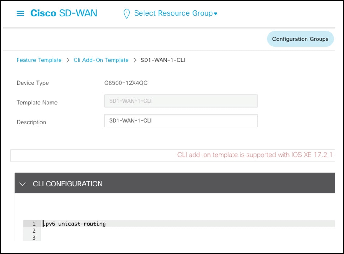
Enable IPv6 Unicast Routing on the SD-WAN Edge
Enable ipv6 unicast-routing for the SD-WAN edge with the device CLI or the CLI add-on template.
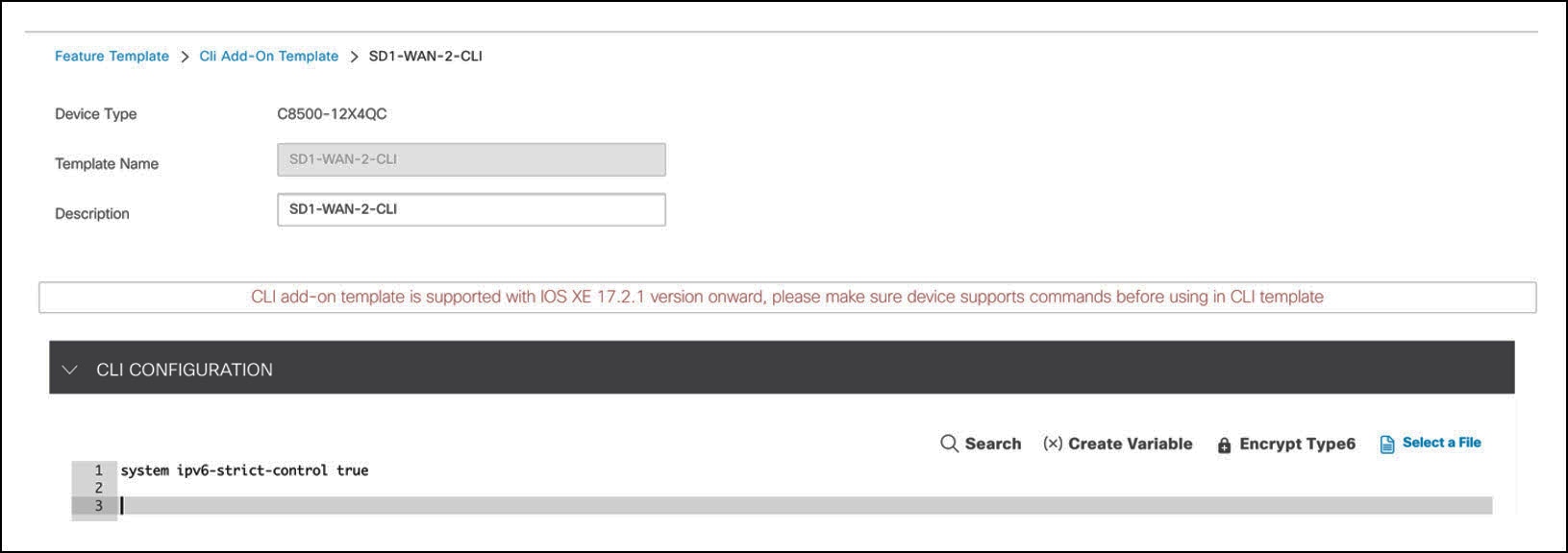
Enable IPv6 Strict Control on the SD-WAN Edge
If dual stack is configured on the transport VPN0 WAN interface, IPv4 takes precedence over IPv6 for both control and data connections. In 17.10/20.10 and later releases, SD-WAN controllers and SD-WAN edges can be configured to prefer IPv6 addresses over IPv4 addresses for forming control connections using the IPv6 Strict Control feature. When IPv6 Strict Control is enabled, the data plane between dual-stack SD-WAN edges establishes over IPv6 transport.
On the SD-WAN edge, enable IPv6 Strict Control with the device CLI or the CLI add-on template.
Deploy DHCPv6 Server with Option 52 on the Distribution Switch
The distribution switch is the SVI gateway for AP traffic. This solution leverages the DHCPv6 server on the switch to provide DHCPv6 option 52 to APs to identify the wireless controller IPv6 address. The following example shows a DHCPv6 server configuration on the distribution switch.
ipv6 dhcp pool vlan1021-ap-ipv6
 address prefix 2001:db8:61:51::/64 lifetime infinite infinite
 dns-server 2001:db8:160::161
 capwap-ac address 2001:db8:150::11

interface Vlan1021
 description SD1_AP_NET
 no ip address
 ipv6 address 2001:db8:61:51::1/64
 ipv6 mtu 1500
 ipv6 dhcp server vlan1021-ap-ipv6
 ospfv3 1 ipv6 area 0
Cisco TrustSec Limitation with IPv6 Deployments
This solution uses IPv6 transport for network protocols, including RADIUS. Cisco TrustSec SGACL and ENV-Data download over IPv6 RADIUS are not supported in Cisco ISE 3.3. As a workaround, this solution leverages the TrustSec HTTP REST Server on Cisco ISE to communicate Cisco TrustSec policy changes and environmental data to the network devices via REST. The environment data and SGACL list timers are lowered from 1 day to 5 minutes to increase the refresh rate. On the network access devices, cts refresh policy can be executed to perform a manual policy refresh if an immediate policy change is required.
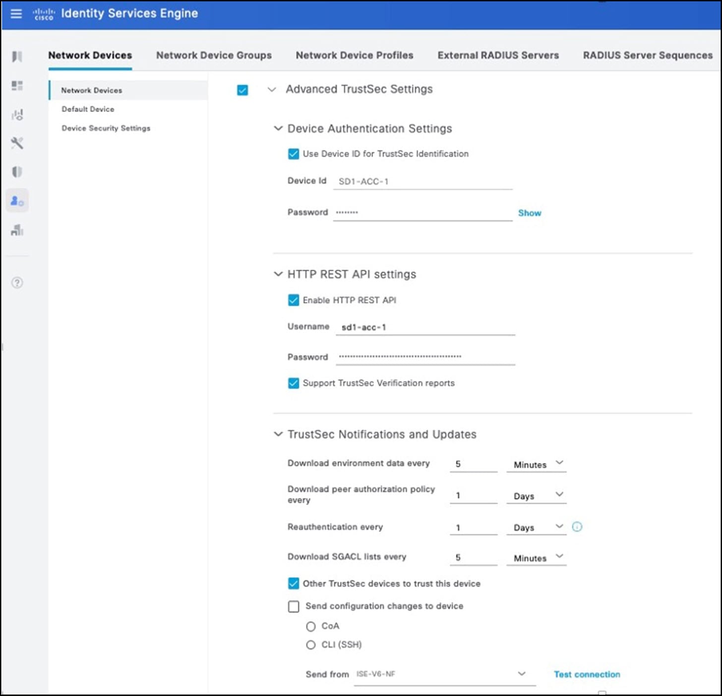
For more information on Cisco TrustSec over REST, see TrustSec HTTPS Servers for Cisco ISE and SGACL and Environment Data Download over REST for the Catalyst switch.
NAT64 on Cisco Firepower
NAT64 is configured on Cisco Firepower and works with DNS64 servers to provide IPv6-only clients with reachability to IPv4 servers on the internet and in the data center shared services block. The IPv6-only client sends a AAAA DNS query of the website to the DNS64 server, which returns a synthetic AAAA DNS response derived from the IPv4 address of the A record of the website. Because the DNS64 IPv6 prefix matches the NAT64 IPv6 prefix configured on Cisco Firepower, client requests to the IPv6 address of the AAAA DNS reply are translated appropriately on the firewall. For information on configuring NAT64 on Cisco Firepower, see Configure NAT 64 on Secure Firewall Managed by FMC.
Enable SGT Propagation on the SD-WAN Edge
Starting from 20.6.1/17.6.1, SGT propagation on the SD-WAN tunnel interface is disabled by default. An extra step is required to enable SGT propagation across SD-WAN. Ensure that CTS SGT propagation is enabled on the WAN transport tunnel interfaces as explained in the following procedure.
Procedure
|
Step 1 |
Enable SGT inline tagging on the SD-WAN edge physical interface. This interface is applied to the VPN0 section of the device template. 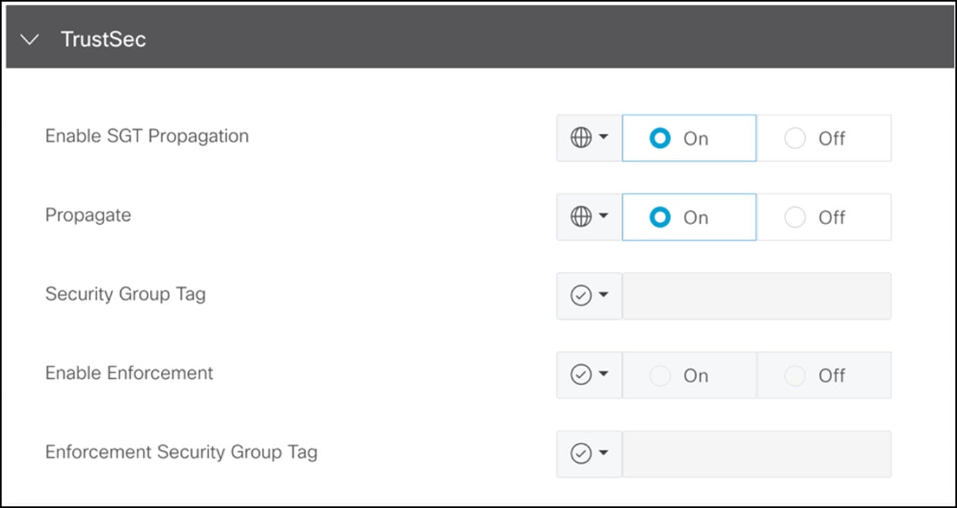
|
|
Step 2 |
Enable SGT inline tagging on the SD-WAN edge service VPN subinterface. 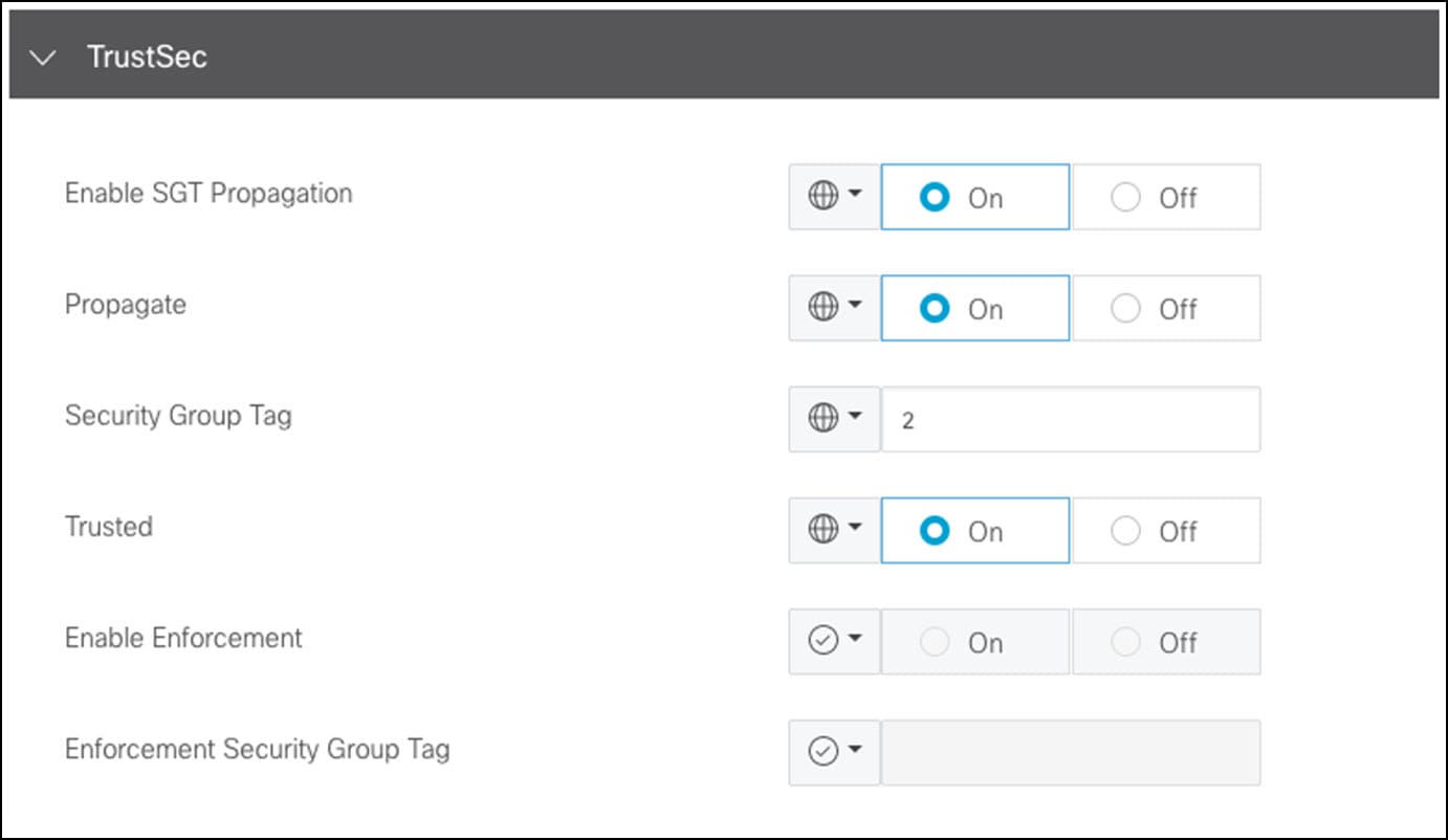
|
|
Step 3 |
Enable CTS SGT propagation on each WAN transport tunnel interface. 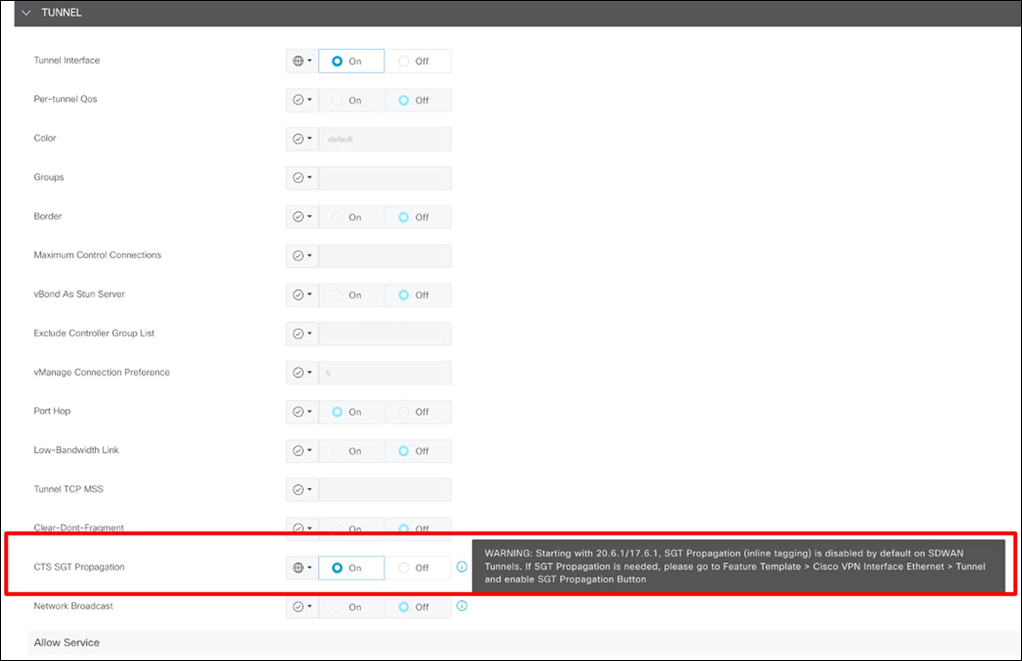
|
Enable Equal Cost Multipath Routing Across Multiple Interfaces
Assigning multiple interfaces to an ECMP zone enables ECMP routing and load balancing across those interfaces.
In the following ECMP configuration, both Outside-1 and Outside-2 interfaces are assigned to the Outside-ECMP zone.
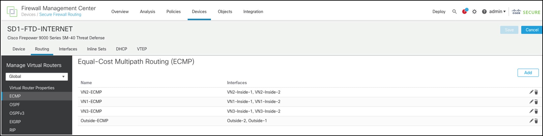
ECMP requires equal cost paths. Configure BGP to install two equal cost routes in the routing table by setting the number of paths to 2 in the BGP settings.
Filter Default Route Advertisement from Core Switch VRF to SD-WAN VPN in Branch Sites
The collapsed core switch VRFs receive default routes from the internet firewall. To prevent the branch site from becoming a transit network for internet traffic from remote sites, filter these default routes from being advertised to the SD-WAN edge. In the following example, the collapsed core switch applies a filter to deny the IPv6 default route while permitting all other prefixes out towards the SD-WAN edge BGP neighbor:
ipv6 prefix-list no-ipv6-default-route seq 5 deny ::/0
ipv6 prefix-list no-ipv6-default-route seq 10 permit ::/0 le 128

router bgp 61002
 address-family ipv6 vrf USER1
  neighbor 2001:db8:0:201::12 remote-as 61021
  neighbor 2002:db8:0:201::12 update-source Vlan3002
  neighbor 2001:db8:0:201::12 fall-over bfd
  neighbor 2001:db8:0:201::12 activate
  neighbor 2001:db8:0:201::12 weight 65535
  neighbor 2001:db8:0:201::12 prefix-list no-ipv6-default-route out
IPv6 Wireless Guest Central Web Authentication
Cisco ISE 3.3 introduces support of the IPv6 Guest Portal. The following procedure explains how to enable the IPv6 Guest Portal and configure the authorization policies on Cisco ISE. It also explains how to manually configure the redirect ACL on the wireless controller to match the redirect ACL name referenced in the Cisco ISE authorization profile.
Procedure
|
Step 1 |
Create a new IPv6 Guest Portal by copying the Self-Registered Guest Portal (default) to Self-Registered Guest Portal IPv6. |
|
Step 2 |
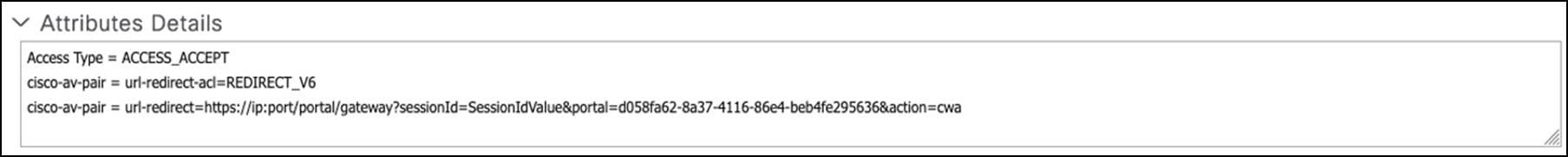
Configure authorization profiles. From , add the profile. Check the Web Redirection check box and enter the ACL name to match the redirect IPv6 ACL configured on the wireless controller. The value is the name of the IPv6 Guest Portal that was created. 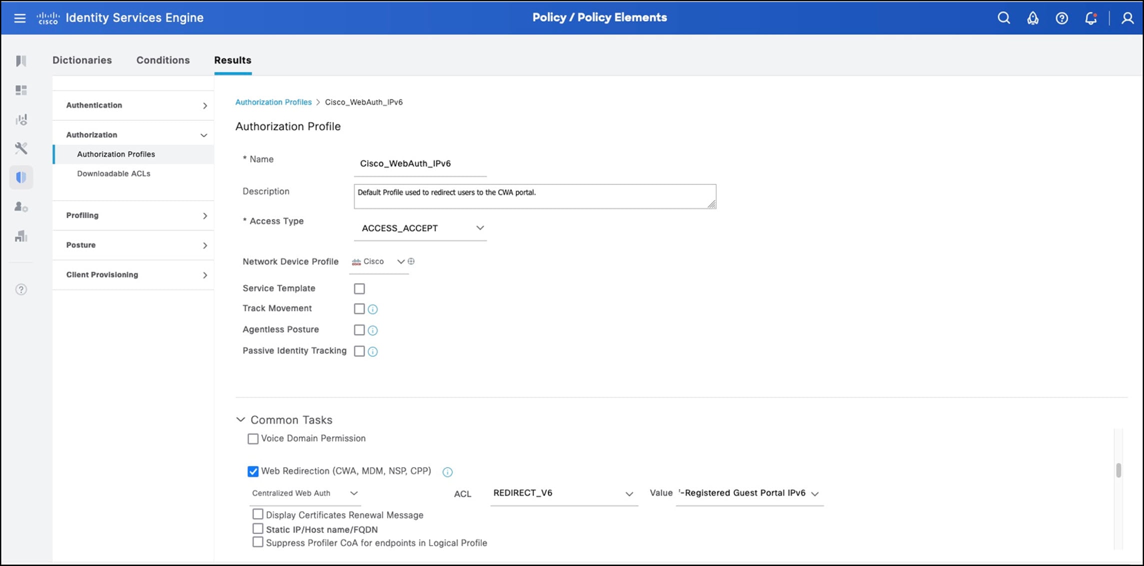
|
|
Step 3 |
Configure the redirect policy. From , two authorization policies are created for the guest SSID: one is the guest access policy; the other is the redirect policy. The Guest Redirect policy redirects the guest user to the portal. The order of these two policies is important. After the guest user successfully authenticates to the portal, it matches the Guest_Flow and Wireless_MAB conditions, is permitted access, and is assigned the SGT value for guest. 

|
|
Step 4 |
Configure the redirect ACL in the wireless controller. The redirect ACL for IPv6 is manually configured. The name of the redirect ACL on the wireless controller must match the name in the Cisco ISE authorization profile. The Deny action indicates that matching traffic isn't redirected, which includes DHCP, DNS, and the Cisco ISE portal. The Permit action indicates that matching traffic is redirected, which is all HTTP and HTTPS traffic.
You can also configure the redirect ACL in the CLI: |
Example Guest WLAN Configuration on Catalyst 9800
The following example explains how to configure the guest WLAN on the Catalyst 9800 with the central switching option.
Procedure
|
Step 1 |
Configure the guest WLAN. 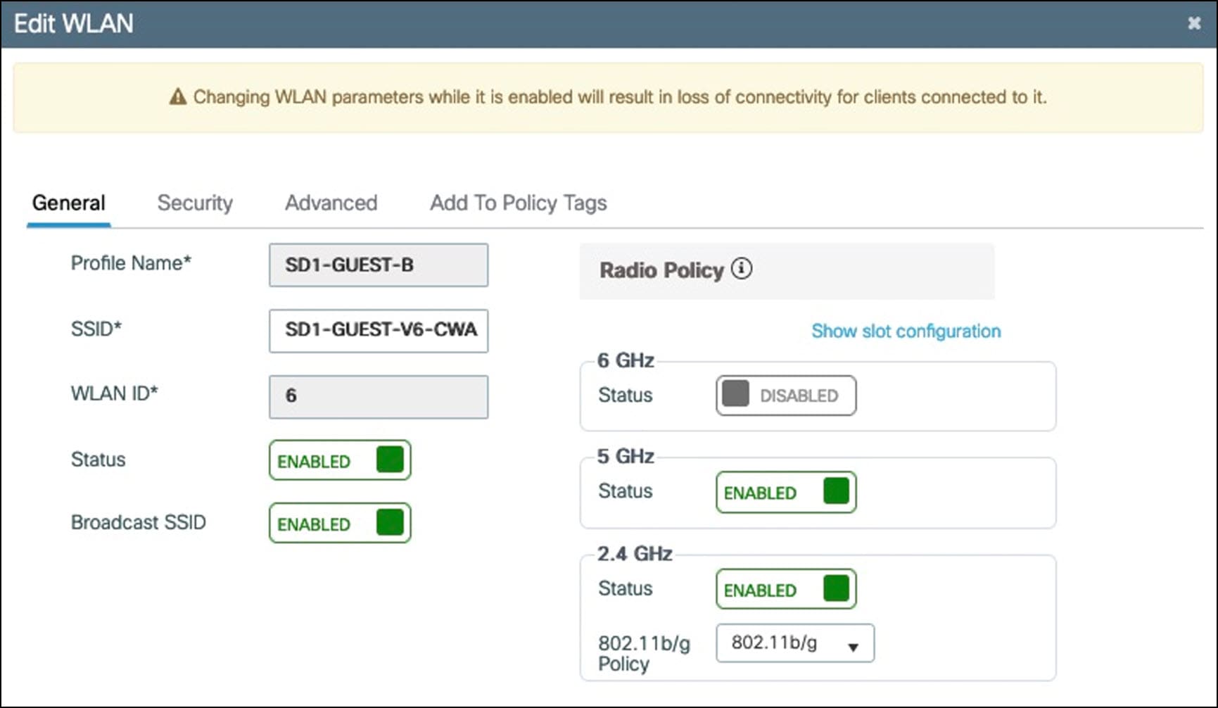
|
|
Step 2 |
Set the Layer 2 security to MAC Filtering and point the authorization list to Cisco ISE. 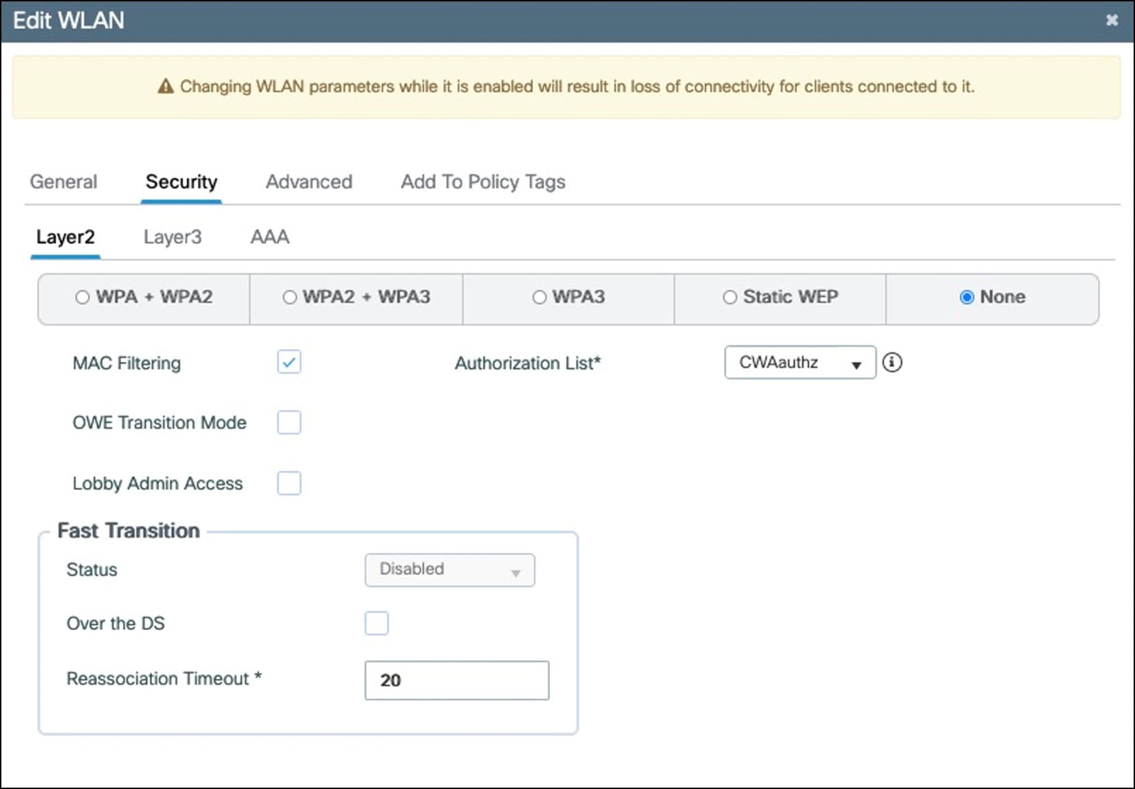
|
|
Step 3 |
Associate the guest WLAN to the policy tag and policy profile. 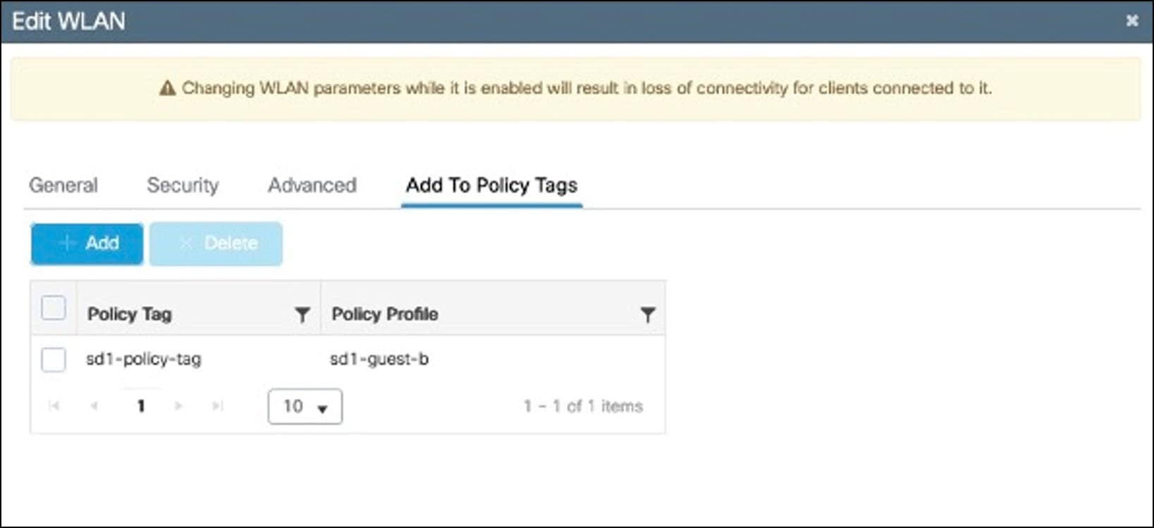
|
|
Step 4 |
Configure the policy profile with the Central Switching, Central Authentication, and Central DHCP options enabled. 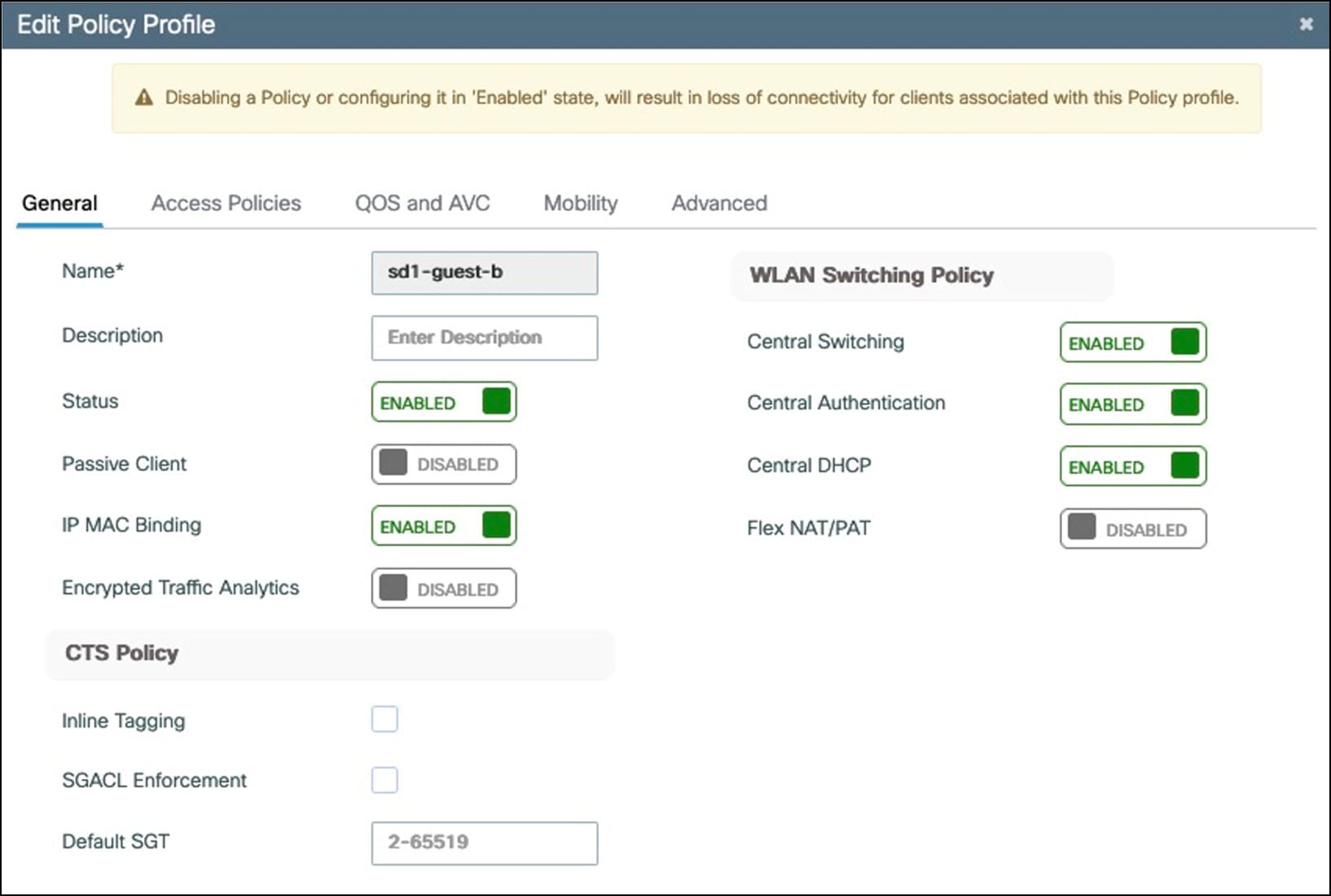
|
|
Step 5 |
In the Access Policies tab, enter the VLAN name to map the Layer 2 VLAN to the WLAN SSID. 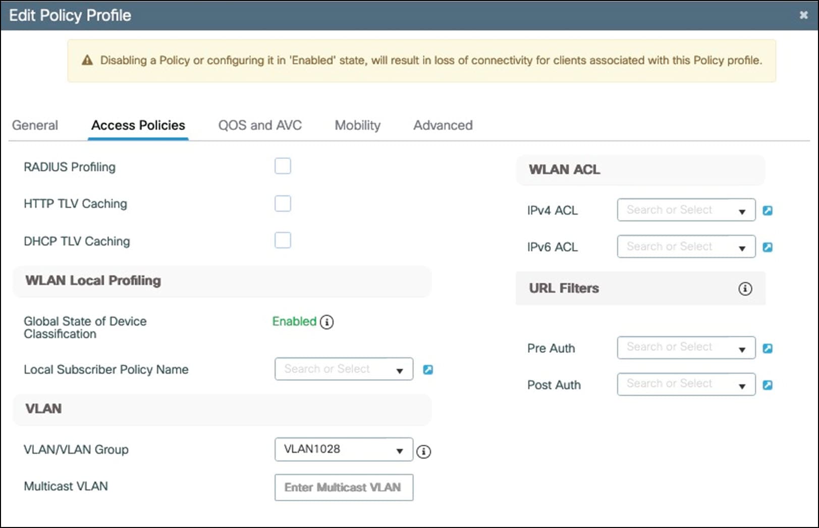
|
|
Step 6 |
In the Advanced tab, under AAA Policy, enable Allow AAA Override and NAC State. Choose the wireless AAA policy name and accounting list. 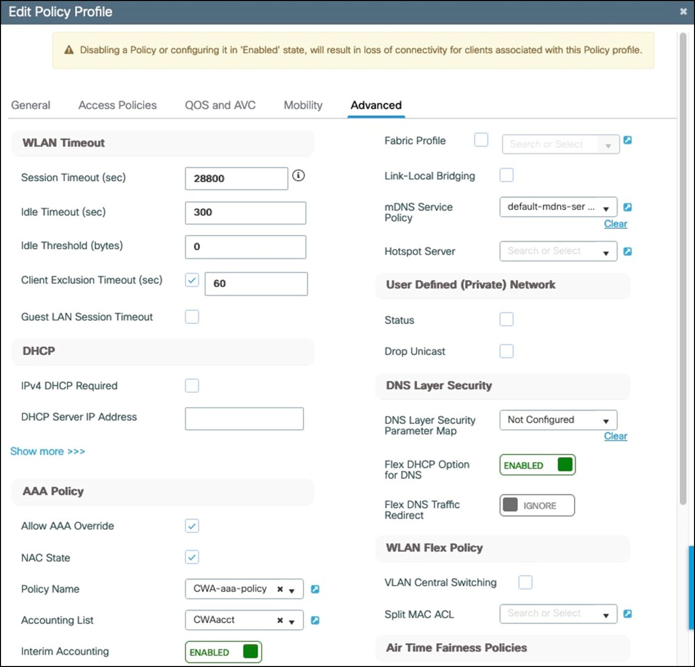
|
IPv6 Multicast Restrictions
IPv6 multicast has the following restrictions in this solution.
-
Cisco SD-WAN 20.12 does not support IPv6 multicast.
-
IPv6 multicast is not supported on Cisco Firepower.
-
IPv6 wireless multicast requires that the Catalyst 9800 wireless controller is configured in Multicast over Multicast (MOM) mode, which relies on the network to replicate multicast traffic. The wireless controller is a multicast server, and all APs are receivers that join the multicast group. Because IPv6 multicast is not supported across SD-WAN, the CAPWAP v6 multicast traffic cannot reach the APs across SD-WAN.
 Feedback