The following diagram provides a high-level illustration of how the solution’s components work together within a single pane
of glass to execute the primary supported use cases.
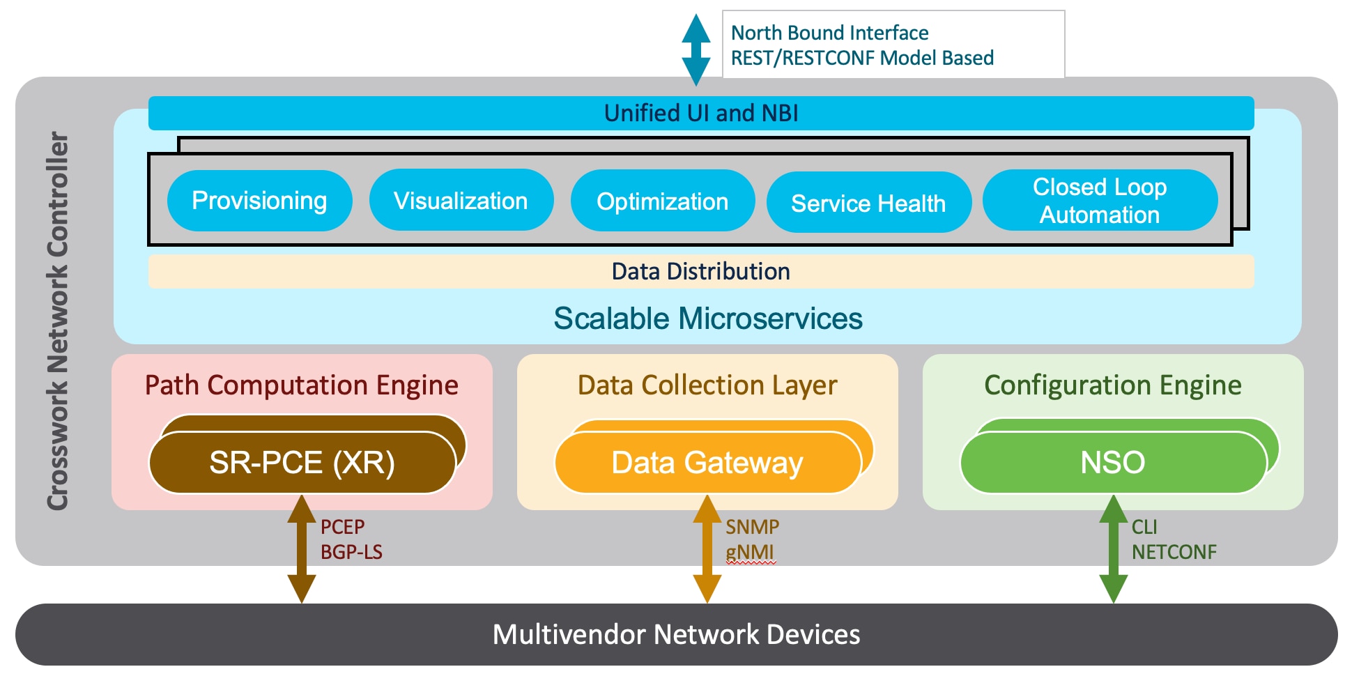
The following components make up the Cisco Crosswork Network Controller 5.0 solution:
Cisco Crosswork Active Topology
Cisco Crosswork Active Topology’s logical and geographical maps provide real-time visibility into the physical and logical
network topology, service inventory, and SR-TE policies and RSVP-TE tunnels, all within a single pane of glass. They enable
operators to see, at-a-glance, the status and health of the devices, services, and policies. Services and transport policies
can be visualized end-to-end as an overlay within the context of the topology map. Cisco Crosswork Active Topology provides
device grouping functionality so that operators can set up their maps to monitor exactly the set of devices, services, and
locations for which they are responsible. In addition, operators can save custom views for quick and easy access to the views
and functionality they use on an ongoing basis.
Cisco Crosswork Optimization Engine
Cisco Crosswork Optimization Engine provides real-time network optimization allowing operators to effectively maximize network
capacity utilization, as well as increase service velocity. Leveraging real-time protocols, such as BGP-LS and Path Computation
Element Communication Protocol (PCEP), SR-PCE and Crosswork Optimization Engine enables closed-loop tracking of the network
state, reacting quickly to changes in network conditions to support a self-healing network.
Cisco Service Health
-
Service Health substantially reduces the time required to detect and troubleshoot service quality issues. It monitors the
health status of provisioned L2/L3 VPN services and enables operators to pinpoint why and where a service is degraded. It
can also provide service-specific monitoring, troubleshooting, assurance, and proactive causality through a heuristic model
that visualizes the:
-
Health status of sub-services (device, tunnel) to a map when a single service is selected
-
Service logical dependency tree and help the operator in troubleshooting in case of degradation by locating where the problem
resides, an indication of possible symptoms, and impacting metrics in case of degradation
-
Historical view of service health status up to 60 days
Service Health also provides the following:
-
Service Health monitoring is available for both Basic Monitoring and Advanced Monitoring options. For help selecting the appropriate
monitoring option for your needs, see the section Basic and Advanced Monitoring Rules.
-
Service Health provides Internal Storage of monitoring data up to a maximum limit of 50 GB. This data is stored on your system. If you exceed the limit of the internal
storage, historical data will be lost. If you choose to extend Service Health storage capacity, you can optionally configure
External Storage in the cloud using an Amazon Web Services (AWS) cloud account. By leveraging External Storage, all existing internal storage
data will be automatically moved to the external cloud storage (see Configuring Service Health External Storage Settings appendix for more details) and your internal storage will act locally as cache storage. Configuring External Storage for
Service Health ensures you will not lose historical data for services that continue to monitor a service’s health, and will
retain service health data for any service you choose to stop monitoring when you select the option to retain historical monitoring
service for the data. For more information on Internal and External Storage, and how to retain historical monitoring service
data when stopped, see the Appendix sections Configuring Service Health External Storage Settings and Stopping Service Health monitoring.

Note
|
If you anticipate monitoring a large amount of Service Health services, Cisco recommends you configure External Storage after
you install Service Health and before you begin monitoring services so to avoid exceeding the Internal Storage and losing
historical data.
|
-
To view subservices supported by Service Health L2VPN/L3VPN, see the Service Health Supported Subservices appendix section. Details are provided that define which subservices are supported by each VPN service flavor.
-
Service Health supports point-to-point L2VPN.
Note
|
Currently, Service Health does not support multipoint L2VPN.
|
-
Service Health supports integration with standalone Network Services Orchestrator (NSO) or NSO Layered Service Architecture
(LSA).
-
NSO LSA support is limited to one CFS node and two RFS nodes. These additional NSO types serve as a high availability feature.
By distributing your devices across the different types, the LSA feature in Service Health allows for dynamic configurations
for assurance.
To manage the Service Health provider Access, select Administration > Manage Provider Access. The Providers screen appears. See the Crosswork Administration guide and NSO documentation for additional, detailed information.
-
The Service Health Collection Jobs administrative option provides the capability to view Parameterized Jobs (template-based
collection jobs) that supports a greater number of jobs, adding the ability to view CLI collection jobs. This is useful when
troubleshooting collection job issues by examining details of individual devices using Parameterized Jobs. Devices are identified
by their Context ID (protocol) to determine if they are GMNI, SNMP, or CLI-based jobs. Additionally, you may export the collection
job information to review. The information is collected at the time the export is initiated and stored in a .csv file.
Note
|
When exporting the collection status, you must fill in the information each time an export is executed. In addition, make
sure to review the Steps to Decrypt Exported File content available on the Export Collection Status pop up to ensure you can
access and view the exported information.
|
-
Service Health provides expanded redundancy/High Availability (HA) for Assurance Graph Manager, Expression Orchestrator, and
Crosswork Expression Tracker microservices (two instances are now available). To view, select Administration > Crosswork Manager. In the Crosswork Summary tab, select Crosswork Service Health to view the Application Details screen and Microservices.
-
For example, if you click the Assurance Graph Manager, two redundant/high availability instances appear. In certain situations,
one of the instances will be in the active-active mode while the other is in the active-standby mode. This ensures that if
one instance goes down, the second acts as a redundant, HA, backup.
-
Heuristic Packages: Three additional Rules have been added to assist in Basic monitoring level rules, where a rule to generate
Assurance Graph information, for example Basic L2VPN NM P2P services, can be used along with two sub services:
-
Rule-L2VPN-NM- Basic
-
Rule-L2VPN-NM-P2P-Basic
-
Rule-L3VPN-NM-Basic
-
Heuristic Package Metrics now has the capability for CLI based metrics and GMNI filtering customizations of packages.
Cisco Crosswork Data Gateway
Cisco Crosswork Data Gateway is a secure, common collection platform for gathering network data from multi-vendor devices.
It is an on-premise application deployed close to network devices. Crosswork Data Gateway supports multiple data collection
protocols including MDT, SNMP, CLI, standards-based gNMI (dial-in), and syslog. Any type of data can be collected by Crosswork
Data Gateway as long as it can be delivered over one of the supported protocols. In this way, it can provide support for a
growing set of use cases and customizations.
To address scale challenges, Cisco Crosswork Data Gateway is implemented as a number of VMs and designed with a distributed
architecture in mind. Each lightweight VM manages a subset of the overall network and as the network grows, additional VMs
can be added horizontally to address the new demands on the compute resources. It also supports a flexible redundancy configuration
based on the operator’s needs. After the initial setup, Cisco Crosswork Network Controller automatically orchestrates the
collection across the multiple Cisco Crosswork Data Gateway VMs.
APIs and configuration examples are available to illustrate how to add new collection jobs (outside of those built for you
by Cisco Crosswork Network Controller) to gather additional information from your network. The collected data can be published
to approved destinations. Supported destinations are Kafka and gRPC messaging bus.
Crosswork Common UI and API
All Cisco Crosswork Network Controller’s functionality are provided within a single, common graphical user interface. This
common UI brings together the features of all Crosswork Network Controller’s components, including common inventory, network
topology and service visualization, service and transport provisioning, and system administration and management functions.
When optional add-on Crosswork components are installed, their functionalities are also fully integrated into the common UI.
Having all functionality within a common UI, instead of having to separately navigate individual application UIs, enhances
the operational experience and increases productivity.
A common API enables Crosswork Network Controller’s programmability. The common APIs provides a single access point for all
APIs exposed by various built-in components. The API provides a REST-based Northbound Interface to external systems (e.g.,
OSS systems) to integrate with Cisco Crosswork Network Controller. RESTCONF and YANG data models are made available for optimization
use cases. For details about the APIs and examples of their usage, see the Cisco Crosswork Network Automation API Documentation on Cisco DevNet.
Crosswork Infrastructure and Shared Services
The Cisco Crosswork Infrastructure provides a resilient and scalable platform on which all Cisco Crosswork components can
be deployed. This infrastructure and shared services provide:
-
A single API endpoint for accessing all APIs of Crosswork applications deployed
-
A shared Kafka bus to pass data between applications
-
Shared database(s) (such as relational and graph) for applications to store data
-
A singe shared database to store all gathered time-series data from the network
-
A robust Kubernetes-based orchestration layer to provide for process-level resiliency
-
Tools for monitoring the health of the infrastructure and the cluster of virtual machines (VMs) on which it resides
Cisco Crosswork Health Insights and Cisco Crosswork Change Automation
Cisco Crosswork Health Insights and Cisco Crosswork Change Automation are components that can optionally be installed with
Cisco Crosswork Network Controller.
Cisco Crosswork Health Insights performs real-time Key Performance Indicator (KPI) monitoring, alerting, and troubleshooting.
Cisco Crosswork Health Insights enables programmable monitoring and analytics. It provides a platform dynamically for addressing
changes to the network infrastructure. Cisco Crosswork Health Insights builds dynamic detection and analytics modules that
allow operators to monitor and alert about network events based on user-defined logic.
Cisco Crosswork Change Automation automates the process of deploying changes to the network. Orchestration is defined via
an embedded Ansible Playbook and then configuration changes are pushed to Cisco Network Services Orchestrator (NSO) to be
deployed to the network.
These components within Cisco Crosswork Network Controller enable closed-loop discovery and remediation of problems in the
network. Operators can match alarms to pre-defined remediation tasks, which are performed when a defined Key Performance Indicator
(KPI) threshold is breached. This reduces the time it takes to discover and repair a problem while minimizing the risk of
human error resulting from manual network operator intervention.
Cisco Crosswork Zero-Touch Provisioning (ZTP)
Cisco Crosswork ZTP can optionally be installed with Cisco Crosswork Network Controller.
Cisco Crosswork ZTP is an integrated turnkey solution for automatically onboarding and provisioning new IOS-XR devices, resulting
in faster deployment of new hardware at lower operating costs. Operators can quickly and easily bring up devices using a Cisco-certified
software image and a day-zero software configuration. After it is provisioned in this way, the new device is onboarded to
the Crosswork device inventory where it can be monitored and managed along with other devices.
Cisco Crosswork ZTP offers Secure ZTP functionality in addition to the Classic ZTP functionality. Secure ZTP is based on RFC
8572 standards and uses secure transport protocols and certificates to verify devices and perform downloads. Secure ZTP is
useful when public Internet resources must be traversed to reach remote network devices, or when the devices are from third-party
manufacturers. With Secure ZTP, the device and the Cisco Crosswork ZTP bootstrap server authenticate each other using the
device's Secure Unique Device Identifier (SUDI) and Crosswork server certificates over TLS/HTTPS. After a secure HTTPS channel
is established, the Crosswork bootstrap server allows the device to request to download and apply a set of signed image and
configuration artifacts adhering to the RFC 8572 YANG schema. After the image (if any) is downloaded and installed, and the
device reloads with the new image, the device downloads configuration scripts and executes them.
Cisco Network Services Orchestrator
Cisco Network Services Orchestrator (NSO) is an orchestration platform that makes use of pluggable function packs to translate
network-wide service intent into device-specific configuration. Cisco NSO provides flexible service orchestration and lifecycle
management across physical network elements and cloud-based virtual network functions (VNFs), fulfilling the role of the Network
Orchestrator (NFVO) within the ETSI (European Telecommunications Standards Institute) architecture. It provides complete support
for physical and virtual network elements, with a consistent operational model across both. It can orchestrate across multi-vendor
environments and support multiple technology stacks, enabling the extension of end-to-end automation to virtually any use
case or device.
Cisco NSO has a rich set of APIs designed to allow developers to implement service applications. It provides the infrastructure
for defining and executing the YANG data models that are needed to realize customer services. It is also responsible for providing
the overall lifecycle management at the network service level.
Service and device models, written using YANG modelling language, enable Cisco NSO to efficiently ‘map’ service intent to
device capabilities and automatically generate the minimum required configuration to be deployed in the network. This feature,
facilitated by Cisco NSO’s FASTMAP algorithm, is capable of comparing current configuration states with a service’s intent
and then generating the minimum set of changes required to instantiate the service in the network.
All Crosswork components that are included in Cisco Crosswork Network Controller or are optional add-ons, with the exception
of Cisco Crosswork ZTP, require integration with Cisco NSO.
Cisco Crosswork Network Controller requires the following Cisco NSO function packs:
-
SR-TE core function pack (CFP) enables provisioning of explicit and dynamic segment routing policies, including SRv6, and
on-demand SR-TE policy instantiation for prefixes with a specific color.
-
Sample function packs for IETF-compliant L2VPN and L3VPN provisioning. These function packs provide baseline L2VPN and L3VPN
provisioning capabilities, based on IETF NM models. Prior to customization, these sample function packs enable provisioning
of the following VPN services:
Cisco Segment Routing Path Computation Element (SR-PCE)
Cisco SR-PCE is an IOS-XR multi-domain stateful PCE supporting both segment routing (SR) and Resource Reservation Protocol
(RSVP). Cisco SR-PCE builds on the native Path Computation Engine (PCE) abilities within IOS-XR devices, and provides the
ability to collect topology and segment routing IDs through BGP-LS, calculate paths that adhere to service SLAs, and program
them into the source router as an ordered list of segments. A Path Computation Client (PCC) reports and delegates control
of head-end tunnels sourced from the PCC to a PCE peer. The PCC and PCE establish a Path Computation Element Communication
Protocol (PCEP) connection that SR-PCE uses to push updates to the network and re-optimize paths where necessary.
Cisco SR-PCE can either reside on server resources using virtualized XRv9000 , or as a converged application running within
IOS-XR Routers.
Note
|
Adding static routes for auto-discovering the scale nodes from SR-PCE after 2,000 nodes is not supported.
|
 Feedback