Cisco Crosswork Hierarchical Controller 7.0 Service Provisioning User Guide
Available Languages
Bias-Free Language
The documentation set for this product strives to use bias-free language. For the purposes of this documentation set, bias-free is defined as language that does not imply discrimination based on age, disability, gender, racial identity, ethnic identity, sexual orientation, socioeconomic status, and intersectionality. Exceptions may be present in the documentation due to language that is hardcoded in the user interfaces of the product software, language used based on RFP documentation, or language that is used by a referenced third-party product. Learn more about how Cisco is using Inclusive Language.
- US/Canada 800-553-2447
- Worldwide Support Phone Numbers
- All Tools
 Feedback
 Feedback
This document is a how-to-use guide for Cisco Crosswork Hierarchical Controller Services Manager.
The document contains the following sections and explains:
● The need for services management
● Tunnels
● Point to Point
● Multi Point
The level of detail attempts to provide an understanding of the solution from an architectural and functional perspective as well as a how-to guide for users to execute the required tasks in the user interface.
Table 1. Terms
| Term |
Definition |
| Adapter |
The software used by Crosswork Hierarchical Controller to connect to a device or to the manager, to collect information required by the network model and configure the device. |
| Agg link |
Agg is Link Aggregation Group (LAG) where multiple ETH links are grouped to create higher bandwidth and resilient link. |
| BGP |
Border Gateway Protocol |
| Circuit E-Line |
An Ethernet connection between two ETH client ports on Transponder or Muxponder over OTN signal. |
| CNC |
Crosswork Network Controller. |
| CO |
Domain controller. |
| Device |
Optical network element, router, or microwave device. |
| Device Manager |
The application that manages the deployed adapters. |
| eMBB |
Enhanced Mobile Broadband. |
| ETH link |
ETH L2 link, spans from one ETH UNI port of an optical device to another, and rides on top of ODU. |
| ETH chain |
A link whose path is a chain of Ethernet links cross-subnet-connected (found using Crosswork Hierarchical Controller cross-mapping algorithm). Eth-chain is a replacement for R_PHYSICAL link in cases where one side of the link is in devices out of the scope discovered by Crosswork Hierarchical Controller. |
| Fiber segment |
Physical fiber line that spans from one passive fiber endpoint (manhole, splice etc.) to another and is used as a segment in a fiber link. |
| Fiber |
Chain of fiber segments that spans from one optical device to another. |
| IGP |
IGP is the link between two routers that carries IGP protocol messages. The link represents an IGP adjacency. |
| IP-MPLS |
IP multi-protocol label switching. |
| L3-VPN link |
The connection between two sites of a specific L3-VPN (can be a chain of LSP connections or IGP path). |
| L3 physical |
L3 physical is the physical link connecting two router ports. It may ride on top of an ETH link if the IP link is carried over the optical layer. |
| L3-VPN |
A virtual private network based on L3 routing for control and forwarding. |
| Logical link, IGP, LSP |
Logical link connects VLANs on two IP ports. |
| LSP |
Label Switched Path, used to carry MPLS traffic over a label-based path. LSP is the MPLS tunnel created between two routers over IGP links, with or without TE options. |
| NMC (OCH-NC, OTSiMC) |
NMC is the link between the xPonder facing ports on two ROADMs. This link is the underlay for OCH and it is an overlay on top of OMS links. This is relevant only for disaggregation cases where the ROADM and OT box are separated. |
| NMS |
Network Management System. |
| OC/OCG |
SONET/SDH links that span from one optical device to another and carry SONET/SDH lower bandwidth services, the links ride on top of OCH links and terminate in TDM client ports. |
| OCH |
OCH is a wavelength connection spanning between the client port one OT device (transponder, muxponder, regen) and another. 40 or 80 OCH links can be created on top of OMS links. The client port can be a TDM or ETH port. |
| OCH-NC |
Wavelength link. New service is added as NMC link. |
| ODU |
ODU links are sub-signals in OTU links. Each OTU links can carry multiple ODU links, and ODU links can be divided into finer granularity ODU links recursively. |
| ONC |
Cisco Optical Controller (ONC). |
| OSPF |
Open Shortest Path First, an Interior Gateway Protocol between routers. |
| OTN-Line |
An OTN connection between two ODU client ports over OTN path. |
| OTS |
OTS is the physical link connecting one line amplifier or ROADM to another. An OTS can be created over a fiber link. |
| out |
OTU is the underlay link in OTN layer, used for ODU links. It can ride on top of an OCH. |
| Packet E-Line |
A point-to-point connection between two routers or transponders/muxponders over MPLS-TP or IP-MPLS. |
| PCC |
Path Computation Client. Delegated to controller. Router is responsible for initiating path setup and retains the control on path updates. |
| PCE |
Path Computation Element. Controller-initiated. |
| QAM |
Quadrature Amplitude Modulation. |
| QPSK |
Quadrature Phase Shift Keying modulation. This carries less information per symbol than QAM modulation. |
| Radio Media |
The media layer as a carrier of radio channels. |
| Radio Channel |
Multiple radio channels can be on top of radio media, each channel represents a different ETH link with its own rate. |
| RD |
Route Distinguisher. |
| RSVP-TE |
Resource Reservation Protocol to control traffic engineered paths over MPLS network . |
| RT |
Route Target. |
| SCH |
A super-channel is an evolution of DWDM in which multiple, coherent optical carriers are combined to create a unified channel of a higher data rate, and which is brought into service in a single operational cycle. |
| SDN Controller |
Software that manages multiple routers or optical network elements. |
| SR Policy |
Segment Routing Policy. A segment routing path between two nodes, with mapping to the IGP links based on SIDs list. |
| STS |
Large and concatenated TDM circuit frame (such as STS-3c) into which ATM cells, IP packets, or Ethernet frames are placed. Rides on top of OC/OCG as optical carrier transmission rates. |
| uRLLC |
Ultra-Reliable Low Latency Communications. |
| VRF |
Virtual Routing Function, acts as a router in L3-VPN. |
| ZR Media |
The media layer as a carrier of ZR channels, on top of OCH link. |
| ZR Channel |
Multiple ZR channels can be on top of ZR media, each channel represents a different IP link with its own rate. |
Crosswork Hierarchical Controller supports the creation of new transport client services and photonic services.
Crosswork Hierarchical Controller abstracts the service model and provides users with a simple and intuitive user interface to provision new services.
It is assumed that domain controller implicitly handles the creation/use of the underlay path (OTSiMC, OTN, MPLS-TP) as required to fulfil the service request.
The table below defines the required parameters per service type.
Crosswork Hierarchical Controller requires the optical controller to support the connectivity-service API by TAPI. A proper use of the layers is needed per the service type.
Table 2. Provisioning parameters
| Service Type |
Provisioning Parameters |
| IP Links |
● Service name ● Service ID ● Link rate mode ● Endpoints and transmit power ● Link IP addresses ● L Band/C Band ● Frequency ● Digital-to-Analog Converter (DAC) rate ● Modulation ● Included nodes/links in path ● Excluded nodes/links from path ● Disjoint from a path of an existing service |
| OCH-NC/OTSiMC (between ROADMs) |
● Service name ● Service ID ● Bandwidth ● Baud rate ● Frequency ● Protection option (1+1, 1+1+r) ● Endpoints ● Optimization goal (minimize path by admin cost, latency, or number of hops) ● Per path, for main, redundant, and restored paths ◦ Included nodes/links in path ◦ Excluded nodes/links from path ● Disjoint from a path of an existing service |
| Photonic Services (OCH Trail between OT/Transponders) |
● Service name ● Service ID ● Bandwidth ● Baud rate ● Frequency ● Protection option (1+1, 1+1+r) ● Endpoints ● Optimization goal (minimize path by admin cost, latency, or number of hops) ● Per path, for main, redundant, and restored paths ◦ Included nodes/links in path ◦ Excluded nodes/links from path ● Disjoint from a path of an existing service |
| Circuit E-Line /OTN Line |
● Service name ● Service ID ● ODU signal/ETH rate ● Protection option (1+1, 1+1+r) ● Endpoints ● Optimization goal (minimize path by admin cost, latency, or number of hops) ● Per path, for main, redundant, and restored paths ◦ Included nodes/links in path ◦ Excluded nodes/links from path ● Disjoint from a path of an existing service |
| Packet E-Line |
● Service name ● Service ID ● Protection option (1+1, 1+1+r) ● Endpoints ◦ CIR/EIR ◦ VLAN IDs ● Optimization goal (minimize path by admin cost, latency, or number of hops) ● Per path, for main, redundant, and restored paths ◦ Included nodes/links in path ◦ Excluded nodes/links from path ● Disjoint from a path of an existing service |
Crosswork Hierarchical Controller in Brief
The Crosswork Hierarchical Controller product family is a set of software applications built on a common Crosswork Hierarchical Controller platform, designed to accelerate automation and to increase efficiency and reliability of service providers networks. Crosswork Hierarchical Controller addresses the role of the multi-domain, multi-layer, and multi-vendor network controller.
Sedona’s innovative capability to learn the mapping between IP/MPLS and optical layer ports (cross-layer mapping) is key to providing a comprehensive view of the network. This has historically been a very difficult problem to solve since there are no standards to automatically provide discovery of such links. This process applies to IP/MPLS-optical links, as well as to cross-domain optical links.
Achieving automation of the complete process, without compromising on resiliency must involve fibers discovery and GIS information. Both enable the understanding of risks in planning phases and crucial information to assess failure impact on services in operations.
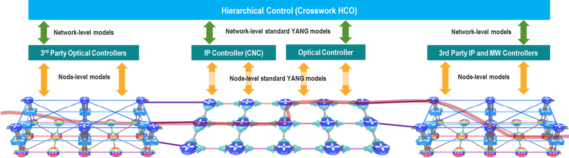
Crosswork Hierarchical Controller is the sole product of its type, in today’s market, that is fully multi-layer and multi-vendor. It is also the only product of this type to be deployed in production by Tier 1 service providers. The system interfaces with SDN Domain Controllers for the packet layers (IP, MPLS) and transport layers (WDM, OTN, Packet-Optical, Microwave) to create a coherent view of the entire transport network, as shown in Figure 1 below, and enables automation of its functions and simplified abstracted interaction with Service Orchestrators and OSS tools.
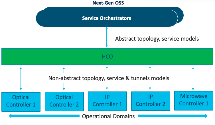
Transport SDN Architecture
Services Management – The Need
Services Manager is a key Cisco Crosswork Hierarchical Controller application that allows for the creation of L1-L3 services and L1-L3 underlay tunnels and links across the entire SP network.
Crosswork Hierarchical Controller can discover L1-L3 services from area/domain controllers. It can discover intra-domain and inter-domain E-Line and L3-VPN services while completing the information on all LSPs along the path, VRFs, and all inter-AS options. This allows Crosswork Hierarchical Controller to discover existing services, as well as new services it has provisioned.
Crosswork Hierarchical Controller supports service lifecycle state (provisioned, pending, planned), operational state and admin state.
Basic service instantiation is supported by the Domain Controller for each domain. However, none of the Domain Controllers understand how to achieve a globally optimal path for an end-to-end service.
Using its own global Path Computation Element (PCE), Crosswork Hierarchical Controller can calculate the optimal end-to-end multidomain path for the service, set it up in each Domain Controller and make sure the service parts are stitched together across domain boundaries.
In fact, a service can span different layers for its delivery. For example, an E-Line service can start on an OTN metro network, then be handed off to the MPLS core network, where it is carried over a pseudowire (PW) in an MPLS tunnel, and then over a packet-optical access network to its final destination. Crosswork Hierarchical Controller figures out which layers should be used to set up the service, based on user-defined policies.
Crosswork Hierarchical Controller supports IP services as defined by IETF in L2NM, L3NM and optical services as defined by ONF TAPI interface.
Crosswork Hierarchical Controller abstracts the service configuration and provides simple, intent-based API and UI to create new services with endpoint details, SLA, and associations to a predefined template that can be overridden for better adjustment.
Services and tunnels currently supported for provisioning and modification by the Services Manager:
● Tunnels:
◦ RSVP-TE tunnel over single domain
◦ SR policy over single domain
● Point-to-Point:
◦ IP links between two routers over ZR/+ and over alien lambda (as multi-vendor optical network)
◦ OCH Link
◦ OCH-NC Link
◦ OTN Line
◦ Circuit E-Line
◦ Packet E-Line over packet-optical network
● Multi-Point:
◦ L3 VPN over multi domain and multi-vendor IP-MPLS (currently in demo mode only)
Service configuration is based on the use of templates (these will be available in a future version). This helps to abstract service provisioning requests, using templates as a reference, and loading service configuration as a basic default that can be overridden per specific request. The configuration will still be able to be overridden for a specific service provisioning request.
Endpoints can be added to the UI wizard by selecting them from the inventory. Ports enabled for selection are those applicable for the service type. Per endpoint, the bandwidth can be defined (as CIR, EIR, CBS, PBS) and VLAN and COS classification can be added.
Crosswork Hierarchical Controller has a sophisticated global multilayer PCE to calculate services and underlay paths. The calculation is based on the selected criteria: number of hops, latency, or admin cost. It also considers the preferences for protection, diversity, SRLG, specific links, devices, or service paths to include or exclude, and resources available per the requested bandwidth.
PCE works over multiple domains, where it can calculate paths’ diversity between domains as a full path of end-to-end service.
Depending on the implementation, PCE knows how to work with vendor-specific capabilities and constraints and how to verify the feasibility of a path before putting it in action.
Creation of a service is managed as a network transaction. Commands are sent to all participating Domain Controllers. Upon completion, the configuration undergoes validation in all domains before notifying the user of configuration success. In the event of failure, PCE knows to roll back and leave no broken configuration in any Domain Controller.
This transaction mechanism knows how to overcome a failure in Crosswork Hierarchical Controller because the backup system can continue tracking the transaction and act according to the response from the Domain Controllers.
Each action on a service or tunnel (creation, modification, deletion) done via the UI or via APIs is recorded as an operation. An operation contains the full details of the action and its results, log of the service scheme sent to the controllers, the returned results, error messages from domain controllers, and the operation status.
Operations can be viewed per selected service or tunnel and as a list of all operations.
Services Manager allows you to view and delete services that were not created by Crosswork Hierarchical Controller but are discovered and managed by the CO (domain controller). For these services, they appear as Is Brownfield: True.
The following delegated service types are supported: Packet E-Line, Circuit E-Line, OTN‑Line, and OCH (Wavelength) services.
A tunnel is a unidirectional link between source and destination routers, riding over IGP links with only primary, or primary and secondary LSPs. You can create tunnels of type:
● RSVP
● SR Policy
You can view a list of the tunnels.
To view tunnels:
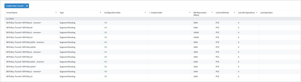
1. In the applications bar in Crosswork Hierarchical Controller, select Services > Services Manager > Tunnels. A list of the tunnels appears in the Tunnels pane with the following information:
◦ Tunnel Name: The tunnel name.
◦ Type: The type of tunnel, for example, Segment Routing.
◦ Configuration State: The configuration state (OK, ABANDONED, REMOVED).
◦ Creation Date: The date the tunnel was created.
◦ BW Reservation (Mbps): The bandwidth reserved for the tunnel.
◦ Control Method: The control method: by device (PCC) or by controller (PCE).
◦ Last 24H Operations: The volume of operations in last 24 hours.
◦ Last Operation: The last operation executed on the tunnel.
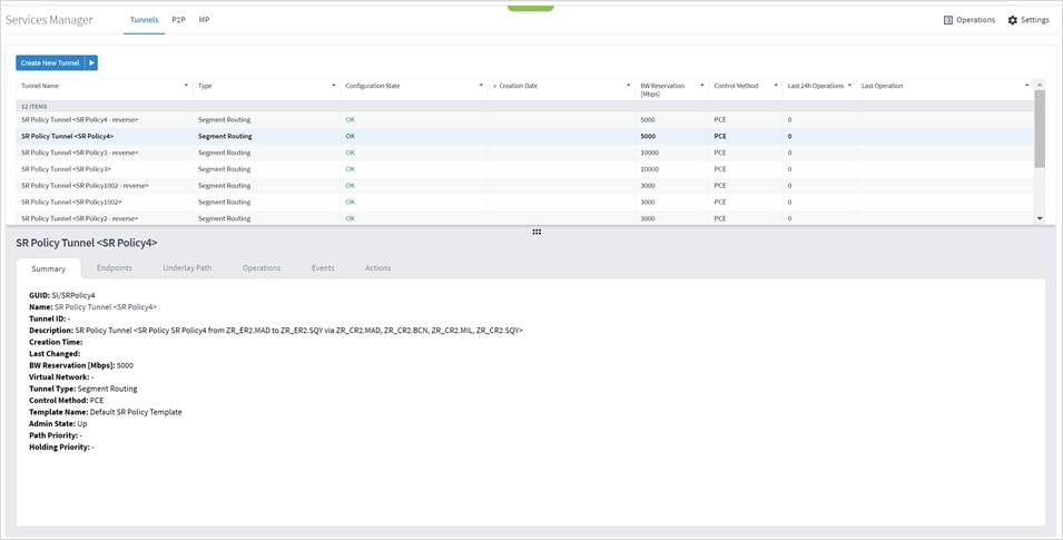
2. Select the required tunnel.
3. To view more tunnel details, see the lower pane view with the following tabs:
◦ Summary: Additional details about the tunnel, such as, Description, Admin State.
◦ Endpoints: The source and destination endpoint details.
◦ Underlay Path: The underlay path items traversed by the tunnel.
◦ Operations: The tunnel operations.
◦ Events: The tunnel events.
◦ Actions: The modification actions (if applicable) and the option to Delete Tunnel.
Add RSVP Tunnel
You can create an RSVP tunnel between source and target endpoints, with a bandwidth reservation, controlled by device or controller, associate with a specific virtual network. Various advanced settings and limitations (items to be included or excluded from the path) can be added. An RSVP tunnel can only be created over a single domain.
To add a RSVP tunnel:
1. In the applications bar in Crosswork Hierarchical Controller, select Services > Services Manager.
1. Click Create New Tunnel.
2. Select RSVP.
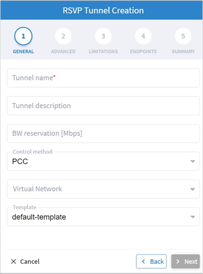
3. Specify the following GENERAL settings:
◦ Tunnel name: The unique user defined name of this tunnel.
◦ Tunnel description: A description of the tunnel.
◦ BW reservation (Mbps): The bandwidth reserved for this tunnel.
◦ Control method: The control method, by device (PCC) or by controller (PCE).
◦ Virtual Network: The virtual network (tunnels can be grouped using tags to construct a virtual network. L3-VPN can be assigned to specific virtual network).
◦ Template: This is not available in the current version (there is a default-template).
4. Click Next.
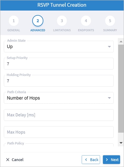
5. Specify the following ADVANCED settings:
◦ Admin State: The admin state (Up or Down).
◦ Setup Priority: The setup priority (between 0 and 7). Default is 7.
◦ Holding Priority: The holding priority (between 0 and 7). Default is 7.
◦ Path Criteria: The path control method (Number of Hops or Latency or Admin Cost).
◦ Max Delay (ms): The maximum permissible delay in 100 of ms (between 0 to 500). Only relevant when the path criteria is set to Latency.
◦ Max Hops: The maximum number of hops (between 1 to 100). Only relevant when path criteria is set to Number of Hops.
◦ Path Policy: Select a policy (Strict or Loose). If Strict, must include the list of nodes and IGP links to be included in the new tunnel path.
6. Click Next.
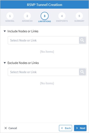
7. Specify the following LIMITATIONS settings:
◦ Include Nodes or Links: Click ![]() and in the Advanced tab, select node or IGP link, or click on the 3D Explorer tab to select node or IGP link.
and in the Advanced tab, select node or IGP link, or click on the 3D Explorer tab to select node or IGP link.
◦ Exclude Nodes or Links: Click ![]() and in the Advanced tab, select node or IGP link, or click on the 3D Explorer tab to select node or IGP link.
and in the Advanced tab, select node or IGP link, or click on the 3D Explorer tab to select node or IGP link.
◦ (Optional) Click ![]() to remove any of the include/exclude items.
to remove any of the include/exclude items.
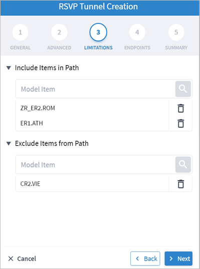
8. Click Next.
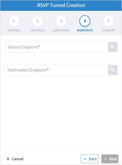
9. Specify the following ENDPOINTS settings:
◦ Source Endpoint: Click ![]() and select the node (router) or IGP interface as the source endpoint.
and select the node (router) or IGP interface as the source endpoint.
◦ Destination Endpoint: Click ![]() and select the node (router) or IGP interface as the destination endpoint.
and select the node (router) or IGP interface as the destination endpoint.
10. Click Next.
11. Review the SUMMARY.
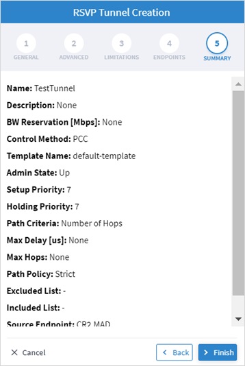
12. Click Finish.
The Crosswork Hierarchical Controller network model supports Segment Routing (SR) Policies and SR Segments over IGP links, and the Crosswork Hierarchical Controller adapters can discover policies from network controllers, with their SID list, color, preference, and candidate path attributes. It maps all discovered policies to create SR Segments as a layer between IGP links and SR policies. An SR Segment is the path between two SIDs, shared by multiple SR policies. An SR Policy tunnel can only be created over a single domain.
To add an SR Policy tunnel:
1. In the applications bar in Crosswork Hierarchical Controller, select Services > Services Manager.
2. Click Create New Tunnel.
3. Select SR Policy.
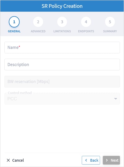
4. Specify the following GENERAL settings:
◦ Name: The unique user defined name of this SR Policy.
◦ Description: A description of the SR Policy.
5. Click Next.
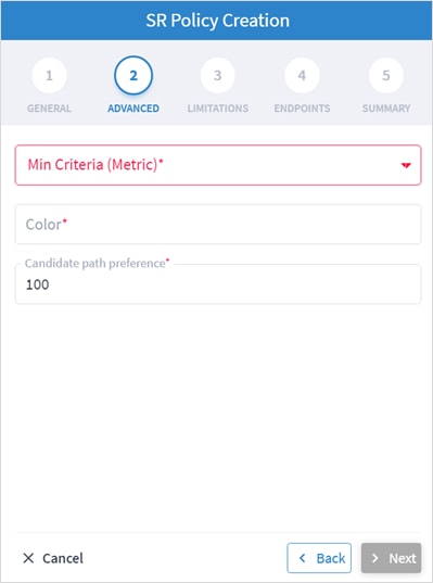
6. Specify the following ADVANCED settings:
◦ Min Criteria (Metric): The criteria metric to minimize (IGP, TE, Delay or Number of Hops).
◦ Color: The SR Policy color (a unique identifier of the policy).
◦ Candidate path preference: The candidate path preference (integer value). The highest preference path is the active one. Multiple candidate paths per policy are currently not support.
7. Click Next.
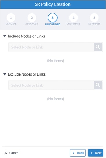
8. Specify the following LIMITATIONS settings:
◦ Include Nodes or Links: Click ![]() and in the Advanced tab, select node or IGP link, or click on the 3D Explorer tab to select node or IGP link.
and in the Advanced tab, select node or IGP link, or click on the 3D Explorer tab to select node or IGP link.
◦ Exclude Nodes or Links: Click ![]() and in the Advanced tab, select node or IGP link, or click on the 3D Explorer tab to select node or IGP link.
and in the Advanced tab, select node or IGP link, or click on the 3D Explorer tab to select node or IGP link.
◦ (Optional) Click ![]() to remove any of the include/exclude items.
to remove any of the include/exclude items.
9. Click Next.
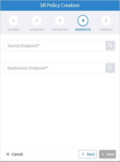
10. Specify the following ENDPOINTS settings:
◦ Source Endpoint: Click ![]() and select the node (router) or IGP interface as the source endpoint.
and select the node (router) or IGP interface as the source endpoint.
◦ Destination Endpoint: Click ![]() and select the node (router) or IGP interface as the destination endpoint.
and select the node (router) or IGP interface as the destination endpoint.
11. Click Next.
12. Review the SUMMARY.
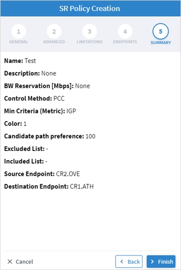
13. Click Finish.
Delete Tunnel
To delete a tunnel:
1. In the applications bar in Crosswork Hierarchical Controller, select Services > Device Manager.
2. Select a tunnel.
3. Select the Actions tab.
4. Click Delete Tunnel. A confirmation message appears.
5. Click Confirm. The tunnel is deleted.
You can create a point-to-point service of type:
● IP Link
● OCH Link
● OCH-NC Link
● OTN-Line
● Circuit E-Line
● Packet E-Line
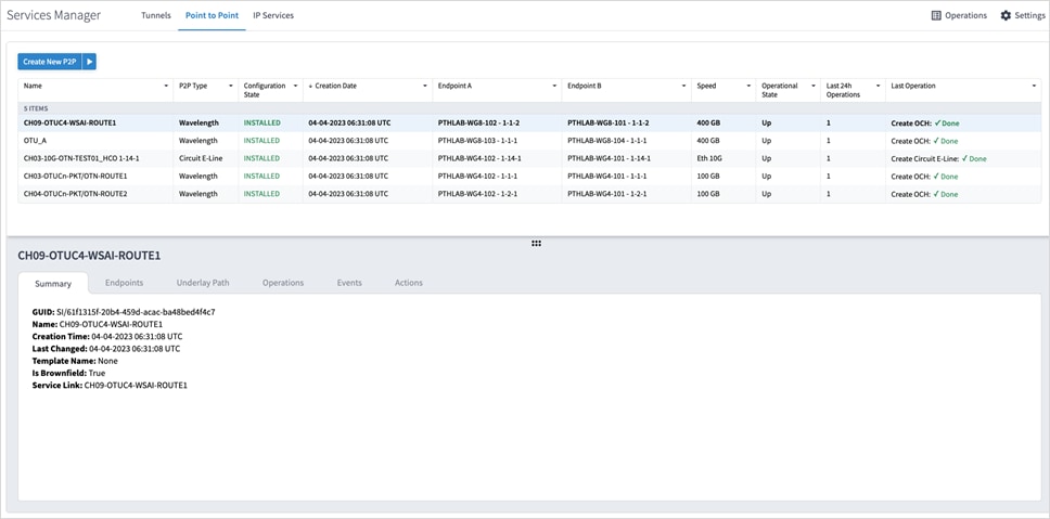
You can view a list of the Point to Point services.
To view PSP services:
1. In the applications bar in Crosswork Hierarchical Controller, select Services > Services Manager > Point to Point. A list of the point-to-point services appears in the Point to Point pane.
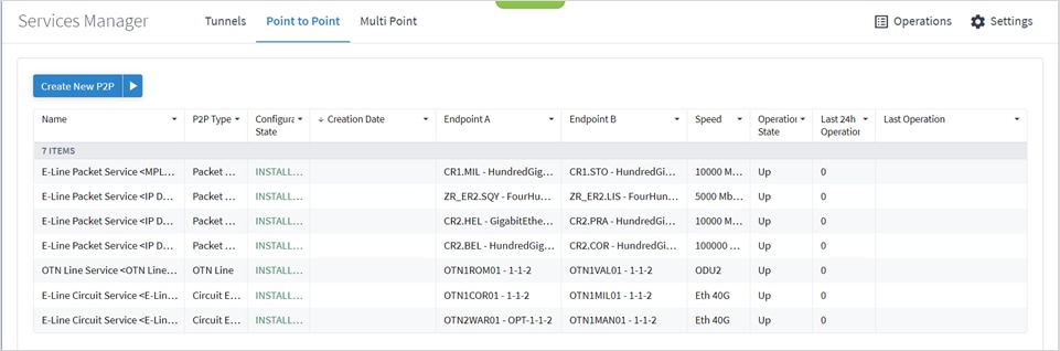
2. Select the required point-to-point service.
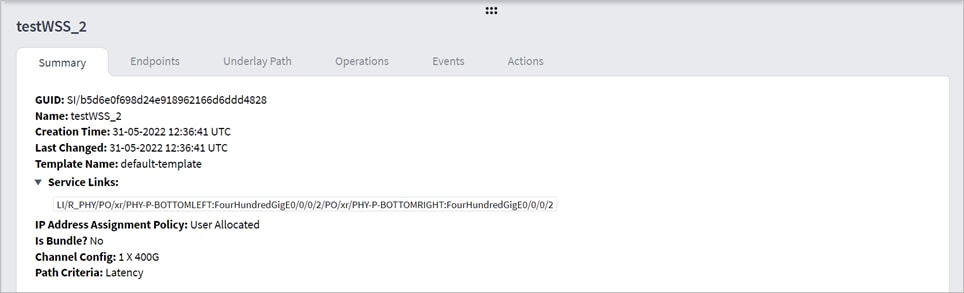
3. To view more point to point link details, see the lower pane view with the following tabs:
◦ Summary: Additional details about the point to point links.
◦ Endpoints: The source and destination endpoint details.
◦ Underlay Path: The underlay path items traversed by the link.
◦ Operations: The point to point link operations.
◦ Events: The point to point link events.
◦ Actions: The modification actions (if applicable) and the option to Delete P2P.
For services that were created by using the MCP controller and not the Services Management application, the service appears as Is Brownfield: True. The Crosswork Hierarchical Controller MCP adapter discovers these services and creates service intent for each of them. The following delegated service types are supported: Packet E-Line, Circuit E-Line, OTN‑Line, and OCH (Wavelength) services.
You can create an IP Link between two ZR pluggable components in routers (creating a new link or adding it to a LAG). Various advanced settings and limitations (such as node or link to be included in the path or excluded from the path of the OCH Link) can be added. The end-to-end service between ZR/+ ports may optionally traverse through OLSs (or ONEs, Optical Network Elements, Cisco, or 3rd party). Crosswork Hierarchical Controller decomposes the service into domains and provisions the optical line between ROADMs on the optical domain controller. The activation mode works directly from Crosswork Hierarchical Controller to IP and optical domain controllers (CNC, ONC).
ZR and ZR+ pluggables manufactured by Cisco output a maximum of -10dBm. There are ROADM setups that can benefit from or require a stronger signal. The new ZR bright pluggable outputs 0dBm and is supported for IP provisioning. BRT appears in the device description, for example, Cisco QDD 400G BRT ZRP Pluggable Optics Module.
You can create L Band and C Band links. L-Band introduces a second OMS over the line-side OTS.
For example, Fiber-1 (OTS link is used) by two OMS-1 and OMS-2 (OMS links).
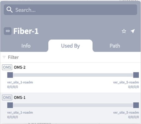
With both L Band and C Band, for a single OTS there are 2 (or more) OMS links.
For example:
Port[.type = "OMS" and .provider = "onc-titan"] | link [.layer = "OMS”]
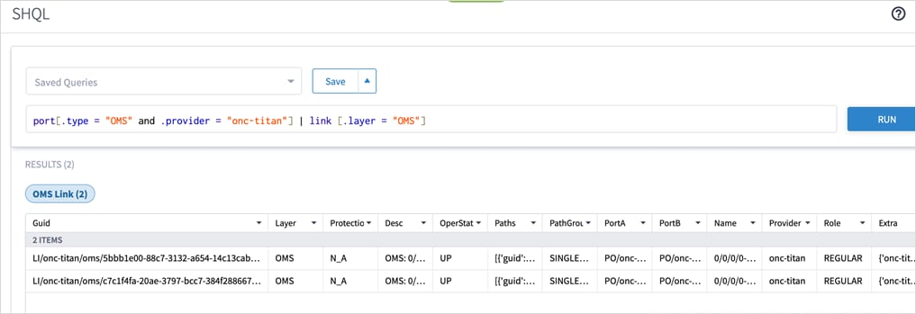
For a single OTS link, there are 2 OTS ports and 4 (or more) OMS ports where the UpperPorts field holds the “upper” OMS ports for each OTS port.
For example:
port[.type = "OMS""] | link | port | downward ("OTS”)
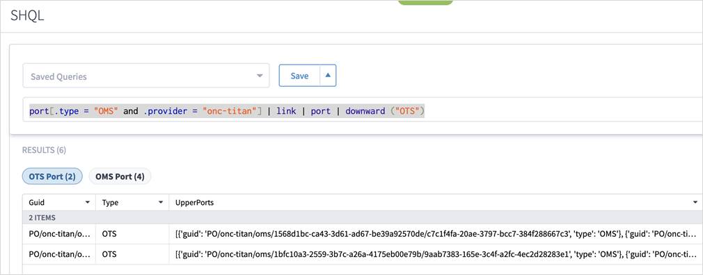
For more info on how to view links and ports in SHQL, see the Cisco Crosswork Hierarchical Controller NBI and SHQL Reference Guide.
To create an IP Link:
1. In the applications bar in Crosswork Hierarchical Controller, select Services > Services Manager.
2. Select the Point to Point tab.
3. Click IP Link.
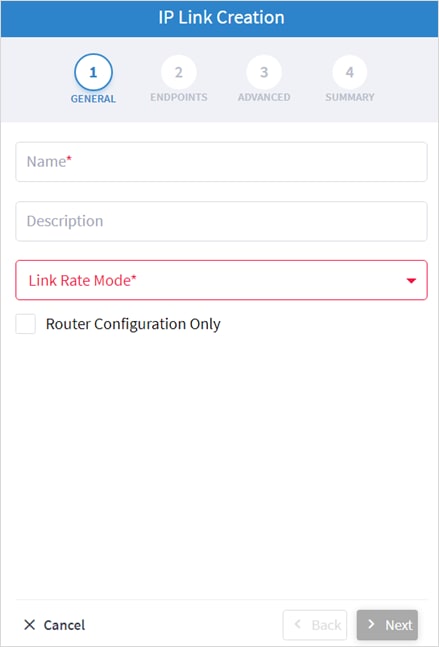
4. Specify the following GENERAL settings:
◦ Name: Enter a name for the service.
◦ Description: Enter a description for the service.
◦ Link Rate Mode: Select a link rate mode, for example, 100G – 1x100G. Bundles are offered when the selected rate is for muxponder mode. From version 7.0, a bundle option is offered for 400G.
◦ Router Configuration Only: Select this option when configuring a router only (direct routers connections, not via OLS).
5. Click Next.
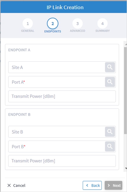
6. Specify the following ENDPOINTS settings:
◦ Site A: Click ![]() and in the Advanced tab, select a site, or click on the 3D Explorer tab to select a site.
and in the Advanced tab, select a site, or click on the 3D Explorer tab to select a site.
◦ Port A: Click ![]() and in the Advanced tab, select an OCH port, or click on the 3D Explorer tab to select a port. If the port selected is an adjacency port, endpoint B is automatically updated and cannot be edited.
and in the Advanced tab, select an OCH port, or click on the 3D Explorer tab to select a port. If the port selected is an adjacency port, endpoint B is automatically updated and cannot be edited.
◦ Transmit Power (dBm): Select the transmit power for Endpoint A.
◦ Site B: Click ![]() and in the Advanced tab, select a site, or click on the 3D Explorer tab to select a site.
and in the Advanced tab, select a site, or click on the 3D Explorer tab to select a site.
◦ Port B: Click ![]() and in the Advanced tab, select an OCH port, or click on the 3D Explorer tab to select a port.
and in the Advanced tab, select an OCH port, or click on the 3D Explorer tab to select a port.
◦ Transmit Power (dBm): Select the transmit power for Endpoint B.
◦ LINK #1 IP ADDRESSES: Enter the IP Address A (CIDR) and IP Address B (CIDR).
◦ (Optional depending on the Link Rate Mode selected) Enter the LINK #2 IP ADDRESSES, LINK #3 IP ADDRESSES and LINK #4 IP ADDRESSES.
7. Click Next.
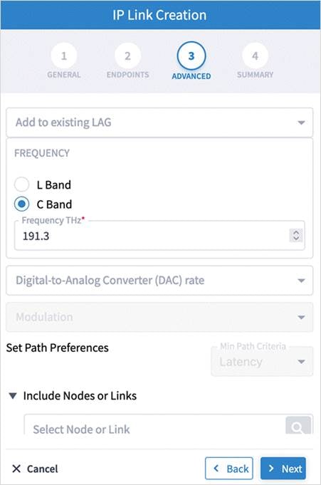
8. Specify the following ADVANCED settings:
◦ Add to existing LAG: Select one of the existing LAGs (bundles) between the two selected routers. This option is only available if there is a bundle already configured between the routers.
◦ Frequency: Select L Band or C Band and specify the Frequency Thz for this link. L-Band introduces a second OMS over the line-side OTS.
◦ Digital-to-Analog Converter (DAC) rate: The DAC rate is only relevant for ZR+ and bright ZR port selection. For 100G, there is no need to change the DAC rate. Select 1 X 1 (standard compatible mode) or 1 X 1.25 (Cisco-proprietary mode if both ends of the link are Cisco pluggables). For QAM modulation, only 1 x 1.25 is supported.
◦ Modulation: Select 8 QAM, 16 QAM or QPSK (default) to reduce the baud rate for 200G links. It is not necessary to apply modulation to 100G, 300G or 400G links as the correct modulation is automatically applied: 100G (QPSK), 300G (8 QAM) and 400G (16 QAM).
◦ Set Path Preferences: Not enabled. Set to Latency.
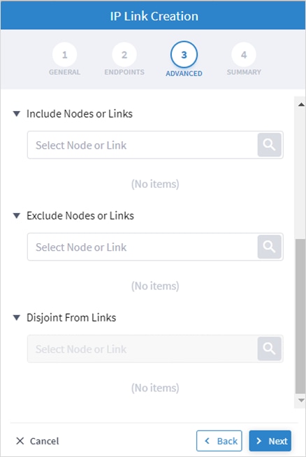
◦ Include Nodes or Links: Click ![]() and in the Advanced tab, select a ONE node or OTS/OMS link, or click on the 3D Explorer tab to select the required item.
and in the Advanced tab, select a ONE node or OTS/OMS link, or click on the 3D Explorer tab to select the required item.
◦ Exclude Nodes or Links: Click ![]() and in the Advanced tab, select a ONE node or OTS/OMS link, or click on the 3D Explorer tab to select the required item.
and in the Advanced tab, select a ONE node or OTS/OMS link, or click on the 3D Explorer tab to select the required item.
◦ Disjoint From Link: Not enabled.
◦ (Optional) Click ![]() to remove any of the include/exclude items.
to remove any of the include/exclude items.
9. Click Next.
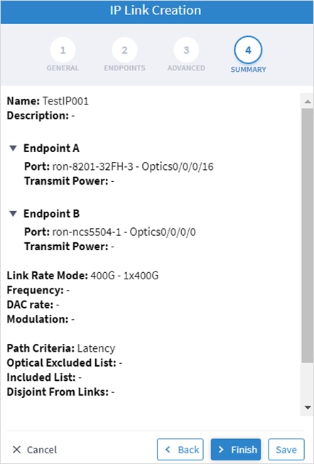
10. Review the SUMMARY.
11. Click Finish.
You can create an OCH Link between line side of Transponders/Muxponders, define its capacity, add 1+1 protection if required, and optimize based on number of hops, latency, or admin cost. Various advanced settings and limitations (such as nodes or links to be included or excluded from the OCH Link) can be added.
In this phase, the Transponder and the ROADM must be controlled by the same optical controller. A use case of disaggregated topology is planned for future releases.
To create an OCH Link:
1. In the applications bar in Crosswork Hierarchical Controller, select Services > Services Manager.
2. Select the Point to Point tab.
3. Click OCH Link.
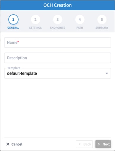
4. Specify the following GENERAL settings:
◦ Name: The unique user defined name of this link.
◦ Description: A description of the link.
5. Click Next.
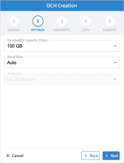
6. Specify the following SETTINGS:
◦ Bandwidth Capacity (Gbps): The bandwidth capacity for this OCH link (100 GB, 200 GB, 300 GB, 400 Gb or 800 GB).
◦ Baud Rate: The baud rate for this IP link (Auto or 35 G or 56 G).
7. Click Next.
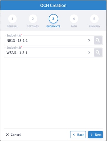
8. Specify the following ENDPOINTS settings:
◦ Endpoint A: Click ![]() and in the Advanced tab, select an OCH endpoint, or click on the 3D Explorer tab to select an OCH endpoint.
and in the Advanced tab, select an OCH endpoint, or click on the 3D Explorer tab to select an OCH endpoint.
◦ Endpoint B: Click ![]() and in the Advanced tab, select an OCH endpoint, or click on the 3D Explorer tab to select an OCH endpoint.
and in the Advanced tab, select an OCH endpoint, or click on the 3D Explorer tab to select an OCH endpoint.
9. Click Next.

10. Specify the following PATH settings:
◦ Optimization Goal: The optimization goal (Number of Hops or Latency or Admin Cost).
◦ Disjoint From Link: ![]() and in the Advanced tab, select an OCH link, or click on the 3D Explorer tab to select an OCH link. This means that the new OTN-Line must not traverse this exclusionary path (this would be equivalent to adding all the links that constitute the disjoint path to the exclude items from path list).
and in the Advanced tab, select an OCH link, or click on the 3D Explorer tab to select an OCH link. This means that the new OTN-Line must not traverse this exclusionary path (this would be equivalent to adding all the links that constitute the disjoint path to the exclude items from path list).
◦ Include Nodes or Links: Click ![]() and in the Advanced tab, select an optical node or OMS link, or click on the 3D Explorer tab to select an optical node or OMS link.
and in the Advanced tab, select an optical node or OMS link, or click on the 3D Explorer tab to select an optical node or OMS link.
◦ Exclude Nodes or Links: Click ![]() and in the Advanced tab, select an optical node or OMS/OTS link, or click on the 3D Explorer tab to select an optical node or OMS/OTS link.
and in the Advanced tab, select an optical node or OMS/OTS link, or click on the 3D Explorer tab to select an optical node or OMS/OTS link.
◦ (Optional) Click ![]() to remove any of the include/exclude items.
to remove any of the include/exclude items.
11. Click Next.
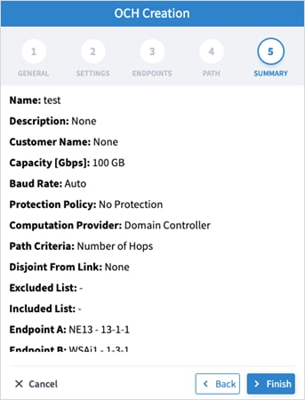
12. Click Finish.
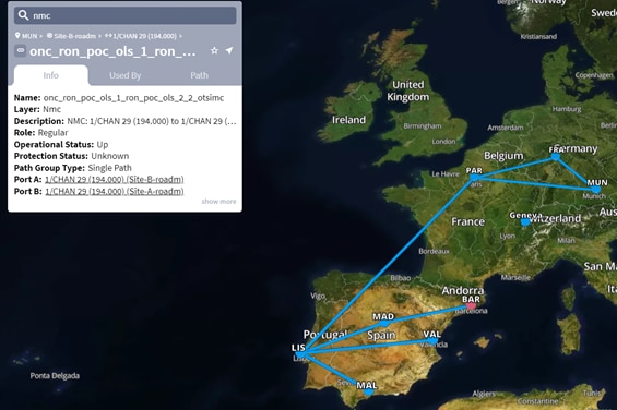
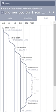
You can create an OCH-NC (or OTSiMC) link. This is the connection between client sides of ROADMs, the ports facing Transponder/Muxponder. You can define its capacity, add 1+1 protection if required, and optimize based on number of hops or admin cost. Various advanced settings and limitations (such as nodes or links to be included or excluded from the OCH-NC Link) can be added.
Before using this wizard, go to the Settings page and upload a file of app codes. Once the file is uploaded, the wizard enables you to select specific codes, which selects an item from the list in the uploaded file.
This only works with Cisco Optical Controller (ONC). The new service is added as an NMC link.
To create an OCH-NC Link:
1. In the applications bar in Crosswork Hierarchical Controller, select Services > Services Manager.
2. Select the Point to Point tab.
3. Click OCH-NC Link.
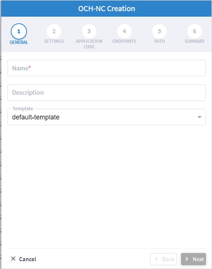
4. Specify the following GENERAL settings:
◦ Name: The unique user defined name of this link.
◦ Description: A description of the link.
5. Click Next.
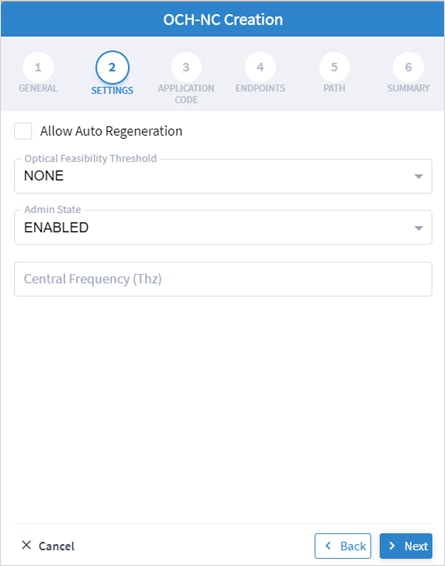
6. Specify the following SETTINGS:
◦ Allow Auto Regeneration: Whether to allow auto regeneration.
◦ Optical Feasibility Threshold: Select RED, GREEN, YELLOW or NONE.
◦ Admin State: Select ENABLED or DISABLED.
◦ Central Frequency (Thz): The frequency for this OCH-NC link. A number in range of nine digits, with a dot after the first 3 digits (xxx.xxxxxx). Range is between 000.000000 to 999.999999 in steps of 000.000001.
7. Click Next.
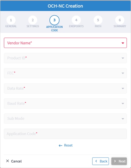
8. Specify the following APPLICATION CODE settings to generate the required Application Code:
◦ Vendor Name: The vendor name.
◦ Product ID: The product ID.
◦ FEC: The FEC depending on the product, for example, CFEC or OFEC.
◦ Data Rate: The data rate supported by the selected product.
◦ Baud Rate: The baud rate supported by the selected product.
◦ Sub Mode: This may appear depending on the other settings.
9. Click Next.
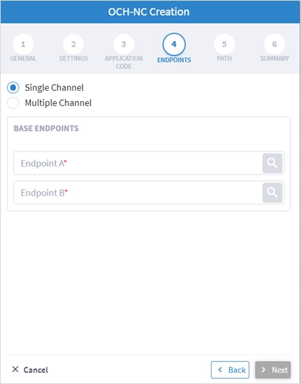
10. Specify the following ENDPOINTS settings:
◦ Select Single Channel or Multiple Channel.
◦ Endpoint A: Click ![]() and in the Advanced tab, select an NMC port, or click on the 3D Explorer tab.
and in the Advanced tab, select an NMC port, or click on the 3D Explorer tab.
◦ Endpoint B: Click ![]() and in the Advanced tab, select an NMC port, or click on the 3D Explorer tab.
and in the Advanced tab, select an NMC port, or click on the 3D Explorer tab.
11. Click Next.
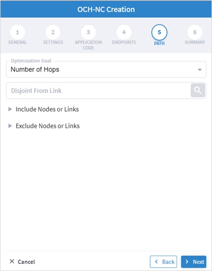
12. Specify the following PATH settings:
◦ Optimization Goal: The optimization goal (Number of Hops or Admin Cost).
◦ Disjoint From Link: ![]() and in the Advanced tab, select an OCH-NC link, or click on the 3D Explorer tab to select an OCH-NC link. This means that the new OCH-NC link must not traverse this exclusionary path (this would be equivalent to adding all the links that constitute the disjoint path to the exclude items from path list).
and in the Advanced tab, select an OCH-NC link, or click on the 3D Explorer tab to select an OCH-NC link. This means that the new OCH-NC link must not traverse this exclusionary path (this would be equivalent to adding all the links that constitute the disjoint path to the exclude items from path list).
◦ Include Nodes or Links: Click ![]() and in the Advanced tab, select a ONES or OMS link, or click on the 3D Explorer tab to select a ONES or OMS link.
and in the Advanced tab, select a ONES or OMS link, or click on the 3D Explorer tab to select a ONES or OMS link.
◦ Exclude Nodes or Links: Click ![]() and in the Advanced tab, select a ONES or OMS/OTS link, or click on the 3D Explorer tab to select a ONES or OMS link.
and in the Advanced tab, select a ONES or OMS/OTS link, or click on the 3D Explorer tab to select a ONES or OMS link.
◦ (Optional) Click ![]() to remove any of the include/exclude items.
to remove any of the include/exclude items.
13. Click Next.
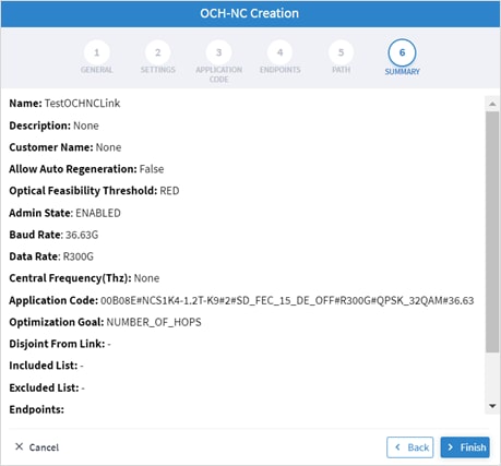
14. Click Finish.
You can create an OTN Line service between OTN client ports on Transponders/Muxponders, define its capacity, add 1+1 protection if required, and optimize based on number of hops, latency, or admin cost. Various advanced settings and limitations (such as node or links to be included in or excluded from the OTN Line) can be added.
To create an OTN Line:
1. In the applications bar in Crosswork Hierarchical Controller, select Services > Services Manager.
2. Select the Point to Point tab.
3. Click OTN Line.
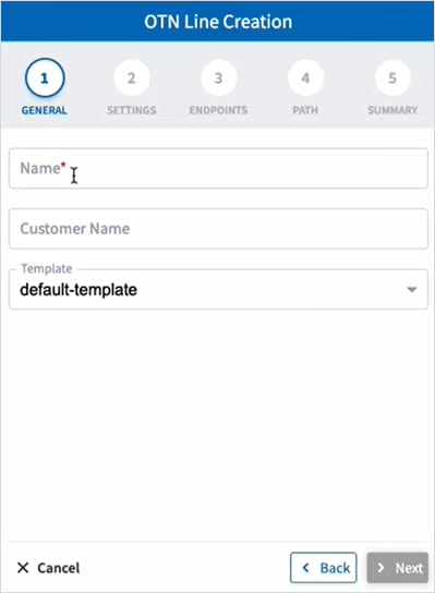
4. Specify the following GENERAL settings:
◦ Name: The unique user defined name of this OTN Line.
◦ Customer Name: The OTN Line customer name.
5. Click Next.
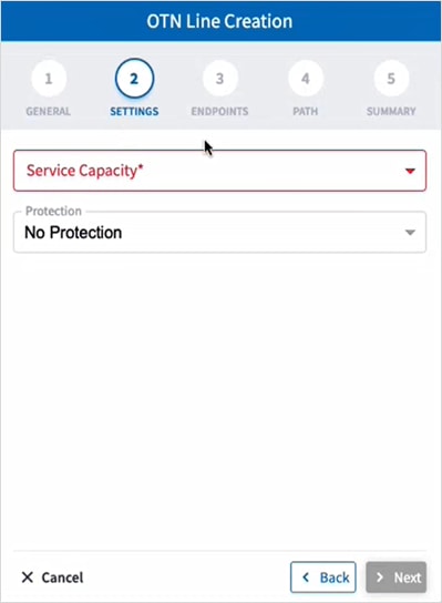
6. Specify the following SETTINGS:
◦ Service Capacity: The capacity for this OTN-Line, for example, ODU2.
◦ Protection: The service protection (No Protection or Protection 1+1).
7. Click Next.
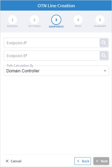
8. Specify the following ENDPOINTS settings:
◦ Endpoint A: Click ![]() and in the Advanced tab, select an endpoint as ODU client port, or click on the 3D Explorer tab to select an endpoint.
and in the Advanced tab, select an endpoint as ODU client port, or click on the 3D Explorer tab to select an endpoint.
◦ Endpoint B: Click ![]() and in the Advanced tab, select an endpoint as ODU client port, or click on the 3D Explorer tab to select an endpoint.
and in the Advanced tab, select an endpoint as ODU client port, or click on the 3D Explorer tab to select an endpoint.
◦ Path Calculation By: Select Domain Controller or HCO.
9. Click Next.
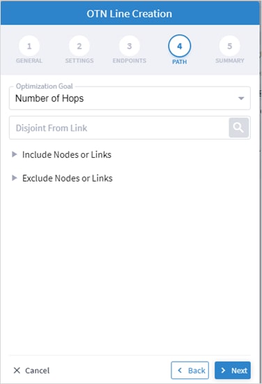
10. Specify the following PATH settings:
◦ Optimization Goal: The optimization goal (Number of Hops or Latency or Admin Cost).
◦ Disjoint From Link: ![]() and in the Advanced tab, select an OTN line, or click on the 3D Explorer tab to select an OTN line. This means that the new OTN Line must not traverse this exclusionary path (this would be equivalent to adding all the links that constitute the disjoint path to the exclude items from path list).
and in the Advanced tab, select an OTN line, or click on the 3D Explorer tab to select an OTN line. This means that the new OTN Line must not traverse this exclusionary path (this would be equivalent to adding all the links that constitute the disjoint path to the exclude items from path list).
◦ Include Nodes or Links: Click ![]() and in the Advanced tab, select a node or OTU link, or click on the 3D Explorer tab to select a node or OTU link.
and in the Advanced tab, select a node or OTU link, or click on the 3D Explorer tab to select a node or OTU link.
◦ Exclude Nodes or Links: Click ![]() and in the Advanced tab, select a node or any optical link, or click on the 3D Explorer tab to select a node or any optical link.
and in the Advanced tab, select a node or any optical link, or click on the 3D Explorer tab to select a node or any optical link.
◦ (Optional) Click ![]() to remove any of the include/exclude items.
to remove any of the include/exclude items.
11. Click Next.
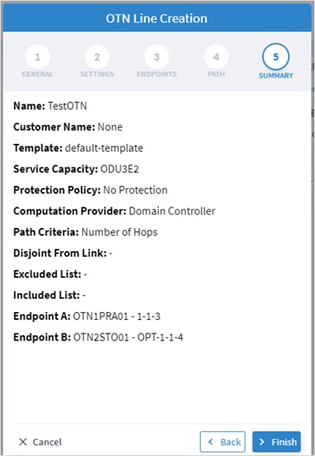
12. Click Finish.
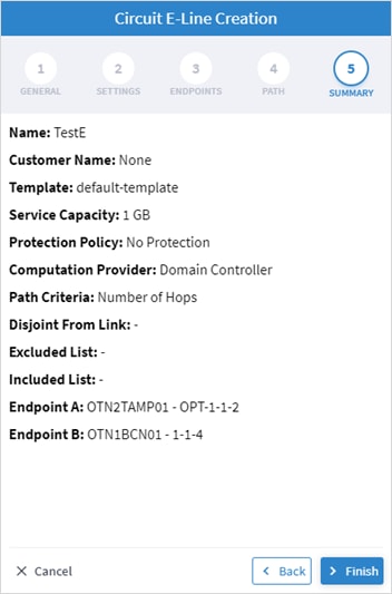
You can create a Circuit E-Line, as an Ethernet connection between ETH client ports on Transponders/Muxponders , define its capacity, add 1+1 protection if required, and optimize based on number of hops, latency, or admin cost. Various advanced settings and limitations (such as nodes or links to be included in or excluded from the Circuit E-line) can be added.
To create a Circuit E-Line:
1. In the applications bar in Crosswork Hierarchical Controller, select Services > Services Manager.
2. Select the Point to Point tab.
3. Click Circuit E-Line.
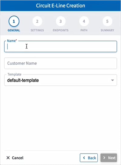
4. Specify the following GENERAL settings:
◦ Name: The unique user defined name of this Circuit E-Line.
◦ Customer Name: The Circuit E-Line customer name.
5. Click Next.
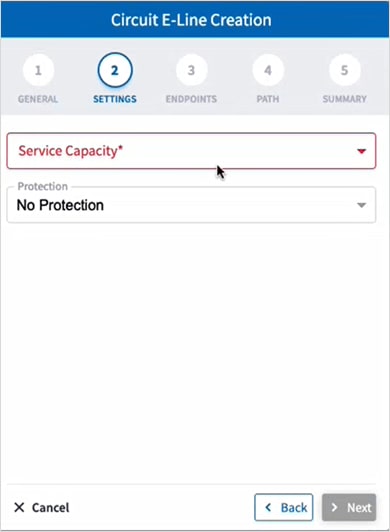
6. Specify the following SETTINGS:
◦ Service Capacity: The capacity for this Circuit E-Line, for example, 10 GB WAN.
◦ Protection: The service protection (No Protection or Protection 1+1).
7. Click Next.
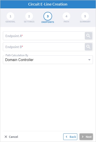
8. Specify the following ENDPOINTS settings:
◦ Endpoint A: Click ![]() and in the Advanced tab, select an ETH endpoint, or click on the 3D Explorer tab to select an endpoint.
and in the Advanced tab, select an ETH endpoint, or click on the 3D Explorer tab to select an endpoint.
◦ Endpoint B: Click ![]() and in the Advanced tab, select an ETH endpoint, or click on the 3D Explorer tab to select an endpoint.
and in the Advanced tab, select an ETH endpoint, or click on the 3D Explorer tab to select an endpoint.
◦ Path Calculation By: Select Domain Controller or HCO.
9. Click Next.
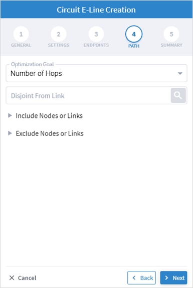
10. Specify the following PATH settings:
◦ Optimization Goal: The optimization goal (Number of Hops or Latency or Admin Cost).
◦ Disjoint From Link: ![]() and in the Advanced tab, select Circuit E-Line, or click on the 3D Explorer tab to select Circuit E-Line. This means that the new Circuit E-Line must not traverse this exclusionary path (this would be equivalent to adding all the links that constitute the disjoint path to the exclude items from path list).
and in the Advanced tab, select Circuit E-Line, or click on the 3D Explorer tab to select Circuit E-Line. This means that the new Circuit E-Line must not traverse this exclusionary path (this would be equivalent to adding all the links that constitute the disjoint path to the exclude items from path list).
◦ Include Nodes or Links: Click ![]() and in the Advanced tab, select a Circuit E-Line, or click on the 3D Explorer tab to select a Circuit E-Line.
and in the Advanced tab, select a Circuit E-Line, or click on the 3D Explorer tab to select a Circuit E-Line.
◦ Exclude Nodes or Links: Click ![]() and in the Advanced tab, select node or any optical link, or click on the 3D Explorer tab to select node or any optical link.
and in the Advanced tab, select node or any optical link, or click on the 3D Explorer tab to select node or any optical link.
◦ (Optional) Click ![]() to remove any of the include/exclude items.
to remove any of the include/exclude items.
11. Click Next.
12. Click Finish.
You can create a Packet E-Line as an Ethernet service between Routers over RSVP-TE tunnels or SR policies, or between Transponders/Muxponders over MPLS-TP tunnels, define its capacity, add 1+1 protection if required, and optimize based on number of hops, latency, or admin cost. Various advanced settings and limitations (such as items to be included or excluded from the Circuit E-line) can be added.
To create a Packet E-Line:
1. Before creating a Packet E-Line service, create the MPLS-TP tunnels to be used (this is assumed to be handled implicitly by the optical controller).
2. In the applications bar in Crosswork Hierarchical Controller, select Services > Services Manager.
3. Select the Point to Point tab.
4. Click Packet E-Line.
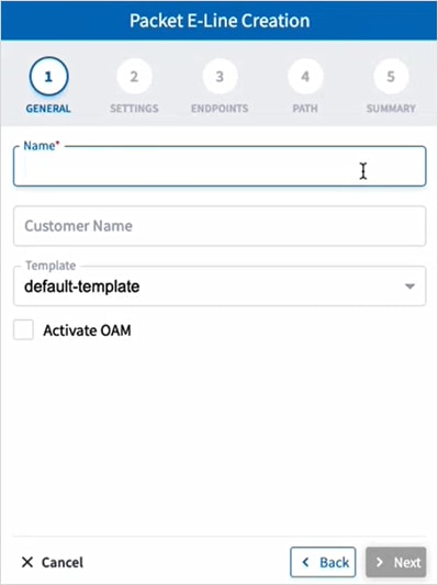
5. Specify the following GENERAL settings:
◦ Name: The unique user defined name of this Packet E-Line.
◦ Customer Name: The Packet E-Line customer name.
◦ Activate OAM: Whether to enable OAM PM activation.
6. Click Next.
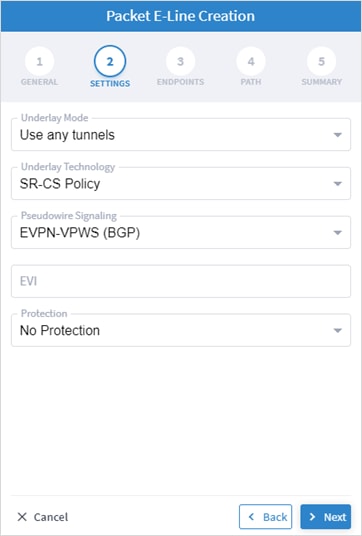
7. Specify the following SETTINGS:
◦ Underlay Mode: The underlay mode, for example, Use any tunnels.
◦ Underlay Technology: The underlay technology, for example, MPLS-TP.
◦ Pseudowire Signaling: The pseudowire signaling, for example, EVPN-VPWS (BGP).
◦ EVI: The EVPN instance.
◦ Protection: The service protection (No Protection or Protection 1+1).
8. Click Next.
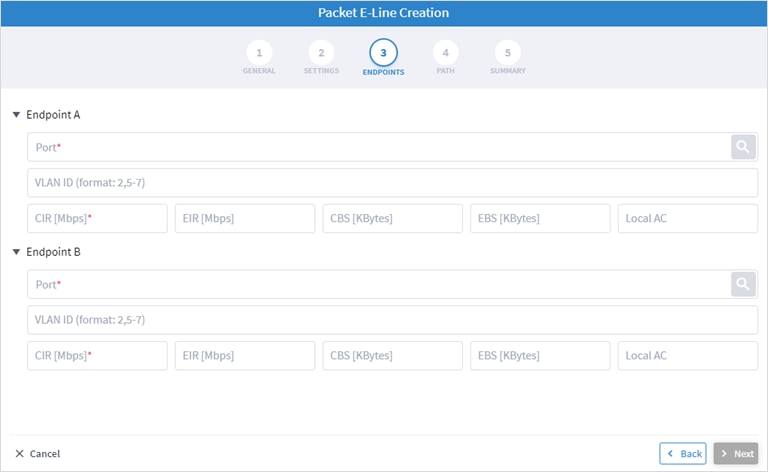
9. Specify the following ENDPOINTS settings for Endpoint A and Endpoint B:
◦ Port: Click ![]() and in the Advanced tab, select a port, or click on the 3D Explorer tab to select an Ethernet port. The port rates should be the same. In case selected ports has already a packet E-Line service defined, with VLAN IDs, the VLAN IDs must be specified for per endpoint for the new service
and in the Advanced tab, select a port, or click on the 3D Explorer tab to select an Ethernet port. The port rates should be the same. In case selected ports has already a packet E-Line service defined, with VLAN IDs, the VLAN IDs must be specified for per endpoint for the new service
◦ VLAN ID: The VLAN ID in a range of 1-4094. Enter a single value, multiple values separate by commas, and/or ranges, where ‘-‘ designates the range, for example: 390-780. . If the selected endpoint has no services on it, the VLAN ID field is optional. Once defined, a VLAN ID must be defined in both endpoints, although different values/ranges can be specified. If you specify multiple VLANs, you must use the same values for both endpoints.
Bandwidth parameters are all optional
◦ CIR (Mbps): The CIR rate in Mbps, range is 0 to <port rate>. The values can be different per endpoint.
◦ EIR (Mbps): The EIR rate in Mbps, range is 0 to <port rate>. The values can be different per endpoint.
◦ CBS (Kbytes): The CBS rate in Kbytes, range is 0 to <port rate>. The values can be different per endpoint.
◦ EBD (Kbytes): The CBS rate in Kbytes, range is 0 to <port rate>. The values can be different per endpoint.
◦ Local AC: The local AC.
◦ Endpoint B: Click ![]() and in the Advanced tab, select a port, or click on the 3D Explorer tab to select a port.
and in the Advanced tab, select a port, or click on the 3D Explorer tab to select a port.
10. Click Next.
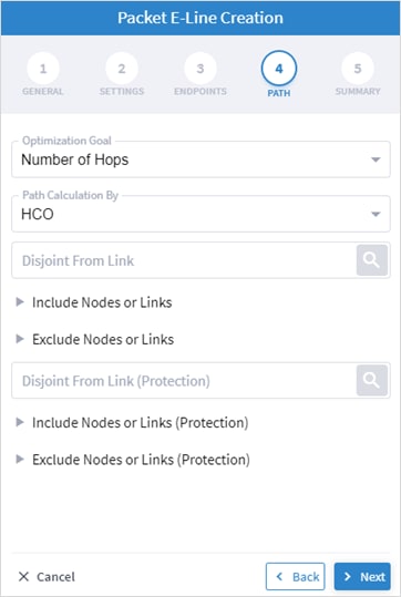
11. Specify the following PATH settings:
◦ (Only required if tunnels are implicitly created) Optimization Goal: The optimization goal (Number of Hops or Latency or Admin Cost).
◦ (Only required if tunnels are implicitly created) Path Calculation By: The path calculation mechanism: Domain Controller or Crosswork Hierarchical Controller. Currently in this version only the Domain Controller option is available.
◦ Disjoint From Link: ![]() and in the Advanced tab, select a Packet E-Line, or click on the 3D Explorer tab to select a Packet E-Line. This means that the new Circuit E-Line must not traverse this exclusionary path (this would be equivalent to adding all the links that constitute the disjoint path to the exclude items from path list).
and in the Advanced tab, select a Packet E-Line, or click on the 3D Explorer tab to select a Packet E-Line. This means that the new Circuit E-Line must not traverse this exclusionary path (this would be equivalent to adding all the links that constitute the disjoint path to the exclude items from path list).
◦ Include Nodes or Links: Click ![]() and in the Advanced tab, select node or underlay link (IGP or OTU), or click on the 3D Explorer tab to select node or underlay link (IGP or OTU).
and in the Advanced tab, select node or underlay link (IGP or OTU), or click on the 3D Explorer tab to select node or underlay link (IGP or OTU).
◦ Exclude Nodes or Links: Click ![]() and in the Advanced tab, select node or underlay link (IGP or OTU) or click on the 3D Explorer tab to select node or underlay link (IGP or OTU).
and in the Advanced tab, select node or underlay link (IGP or OTU) or click on the 3D Explorer tab to select node or underlay link (IGP or OTU).
◦ (Only required with protections) Disjoint From Link (Protection): ![]() and in the Advanced tab, select a Packet E-Line, or click on the 3D Explorer tab to select a Packet E-Line. This means that the new Circuit E-Line must not traverse this exclusionary path (this would be equivalent to adding all the links that constitute the disjoint path to the exclude items from path list).
and in the Advanced tab, select a Packet E-Line, or click on the 3D Explorer tab to select a Packet E-Line. This means that the new Circuit E-Line must not traverse this exclusionary path (this would be equivalent to adding all the links that constitute the disjoint path to the exclude items from path list).
◦ (Only required with protections) Include Nodes or Links (Protection): Click ![]() and in the Advanced tab, select node or underlay link (IGP or OTU), or click on the 3D Explorer tab to select node or underlay link (IGP or OTU).
and in the Advanced tab, select node or underlay link (IGP or OTU), or click on the 3D Explorer tab to select node or underlay link (IGP or OTU).
◦ (Only required with protections) Exclude Nodes or Links (Protection): Click ![]() and in the Advanced tab, select node or underlay link (IGP or OTU) or click on the 3D Explorer tab to select node or underlay link (IGP or OTU).
and in the Advanced tab, select node or underlay link (IGP or OTU) or click on the 3D Explorer tab to select node or underlay link (IGP or OTU).
◦ (Optional) Click ![]() to remove any of the include/exclude items.
to remove any of the include/exclude items.
12. Click Next.
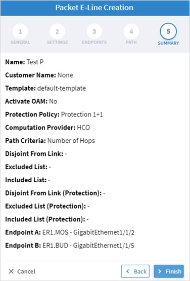
13. Click Finish.
To delete a P2P Link:
1. In the applications bar in Crosswork Hierarchical Controller, select Services > Services Manager > Point to Point.
2. Select a link.
3. Select the Actions tab.
4. Click Delete P2P. A confirmation message appears.
5. Click Accept. The link is deleted.
You can view and add L3-VPN.
To view L3 VPNs:
1. In the applications bar in Crosswork Hierarchical Controller, select Services > Services Manager > Multi Point. A list of the L3VPNs appears in the Multi Point pane.
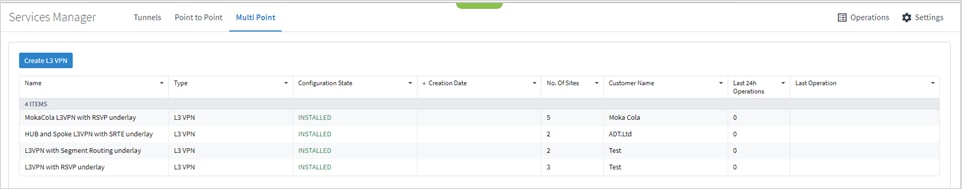
2. Select the required L3 VPN.
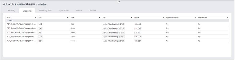
3. To view more L3 VPN details, see the lower pane view with the following tabs:
◦ Summary: Additional details about the L3 VPN.
◦ Endpoints: The endpoint details.
◦ Underlay Path: The underlay path items traversed by the link.
◦ Operations: The L3 VPN link operations.
◦ Events: The L3 VPN link events.
◦ Actions: The modification actions (if applicable) and the option to Delete VPN.
You can add a managed L3 VPN, that is, a VPN created by Crosswork Hierarchical Controller or delegated to Crosswork Hierarchical Controller.
To add an L3 VPN:
1. In the applications bar in Crosswork Hierarchical Controller, select Services > Services Manager
2. Select the Multi Point tab.
3. Click Create L3 VPN.
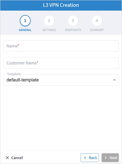
4. Specify the following GENERAL settings:
◦ Name: The unique user defined name of this L3 VPN.
◦ Customer Name: The L3 VPN customer name.
◦ Template: This is not available in the current version (there is a default-template).
5. Click Next.
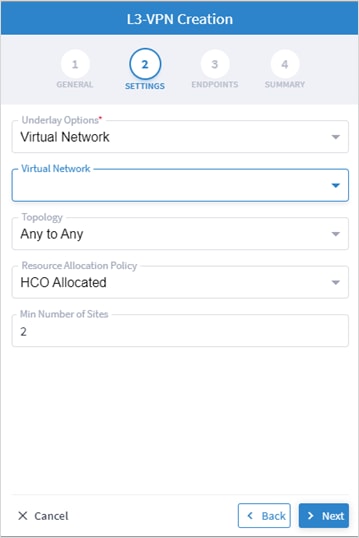
6. Specify the following SETTINGS:
◦ Underlay Options: this is to select whether to map the new service to any tunnels exist between the endpoints or to use only tunnels grouped as a virtual network (you can create new virtual network by creating a tag with the virtual network name as the tag value in the tag key VN). Select All Network or Virtual Network.
◦ Virtual Network: The user created virtual networks (example: uRLLC or eMBB).
◦ Topology: The topology of the L3 VPN (Any to Any, Hub & Spoke, Hub & Spoke Disjoint or Unknown).
◦ Resource Allocation Policy: Refers to allocation of RD and RT, which in this version are allocated by HCO (HCO Allocated, that is, allocated by Crosswork Hierarchical Controller).
◦ Min. Number of Sites: The minimum number of sites/endpoints (between 2 and 20). For Hub & Spoke, select the minimum number of hops and minimum number of spokes separately.
7. Click Next.
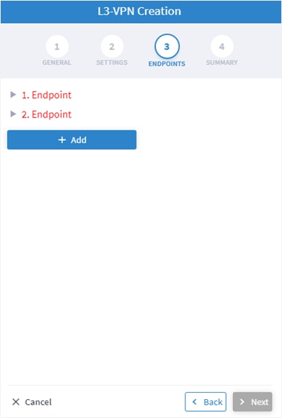
8. Expand the Endpoint.
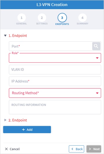
9. Specify the following settings for Endpoint 1 and Endpoint 2:
◦ Port: Click ![]() and in the Advanced tab, select a physical or logical port on a router, or click on the 3D Explorer tab to select a physical or logical port on a router.
and in the Advanced tab, select a physical or logical port on a router, or click on the 3D Explorer tab to select a physical or logical port on a router.
◦ Role: Select Any To Any or Hub or Spoke (depending on the option selected in the SETTINGS tab).
◦ VLAN ID: The VLAN ID in a range of 1-4094. Enter a single value, multiple values separate by commas, and/or ranges, where ‘-‘ designates the range, for example: 390-780. If the selected endpoint has no services on it, the VLAN ID field is optional. Once defined, a VLAN ID must be defined in all endpoints, although different values/ranges can be specified. If you specify multiple VLANs, you must use the same values for all endpoints.
◦ IP Address: The IP address.
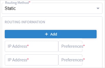
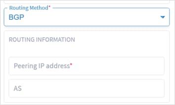
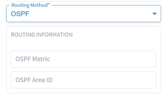
◦ Routing Method: The routing method (Static, BGP or OSPF).
◦ ROUTING INFORMATION: Specify the options depending on the Routing Method selected.
10. If Static, add the static routing information. You can add up to 10 entries, with:
◦ IP Address: The IP address for the destination network in the format xxx.xxx.xxx.xxx/CIDR. The CIDR is a number (between 1 and 32).
◦ Preferences: The preference to allow next hop selection control where the customer prefixes are learned via multiple sources or multiple gateways using the same information source (between 0 and 255).
11. If BGP, add:
◦ Peering IP address: The directly connected IP address of the Customer CE device.
◦ AS: The BGP Autonomous System number to peer with the Customer CE (between 64512 and 655535).
12. If OSPF, add:
◦ OSPF Metric: An optional parameter to denote the cost of the CE-PE link (0 to 65535).
◦ OSPF Area ID: The OSPF area ID that will be used for the CE-PE link (0 to 4294967295).
13. Click Add to add additional endpoints (up to 100).
14. Click Next.
15. Review the SUMMARY.
16. Click Finish.
You can configure which rollbacks are allowed.
To view the service settings:
1. In the applications bar in Crosswork Hierarchical Controller, select Services > Services Manager > Settings. A list of the service settings appears.
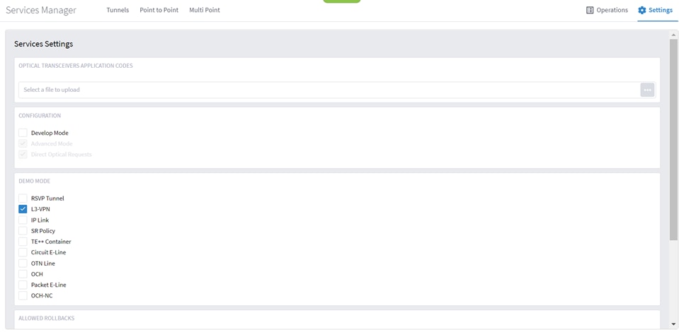
2. In OPTICAL TRANSCEIVERS APPLICATION CODES, click ![]() to select a file with the application codes.
to select a file with the application codes.
3. Select which rollbacks are allowed when the services are provisioned (RSVP Tunnel, L3-VPN, IP Link, SR Policy, TE++ Container, Circuit E-Line, OTN Line, OCH, Packet E-Line and/or OCH-NC).
You can view the latest Services Manager operations.
To view the operations:
1. In the applications bar in Crosswork Hierarchical Controller, select Services > Services Manager > Operations. A list of the operations appears.
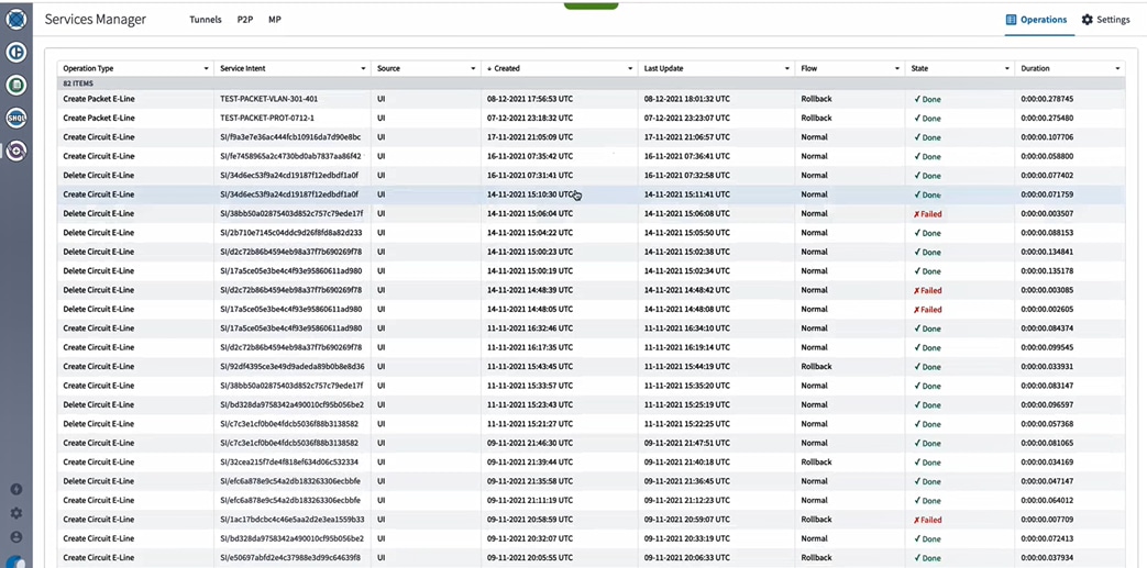
2. Select the required operation.
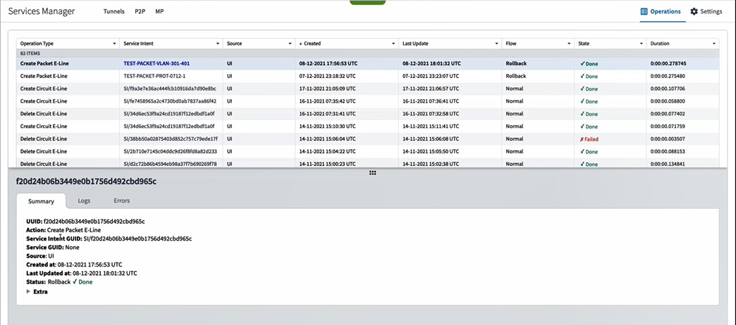
3. To view more details, select the required tab:
◦ Summary: Additional details about the operation, e.g., Status: Rollback Done.
◦ Logs: The operation logs for normal and rollback flows.
◦ Errors: The operation errors, e.g., Discovery took too long.![]()