Getting Started

About the Cisco Application Policy Infrastructure Controller Enterprise Module (APIC-EM)

The Cisco Application Policy Infrastructure Controller - Enterprise Module (APIC-EM) is Cisco's Software Defined Networking (SDN) Controller for Enterprise Networks (Access, Campus, WAN and Wireless).

The platform hosts multiple applications (SDN apps) that use open northbound REST APIs that drive core network automation solutions. The platform also supports a number of south-bound protocols that enable it to communicate with the breadth of network devices that customers already have in place, and extend SDN benefits to both greenfield and brownfield environments.

The Cisco APIC-EM platform supports both wired and wireless enterprise networks across the Campus, Branch and WAN infrastructures. It offers the following benefits:

  • Creates an intelligent, open, programmable network with open APIs

  • Saves time, resources, and costs through advanced automation

  • Transforms business intent policies into a dynamic network configuration

  • Provides a single point for network wide automation and control

The following table describes the features and benefits of the Cisco APIC-EM.

Table 1  Cisco APIC Enterprise Module Features and Benefits

Feature

Description

Network Information Database

The Cisco APIC-EM periodically scans the network to create a “single source of truth” for IT. This inventory includes all network devices, along with an abstraction for the entire enterprise network.

Network topology visualization

The Cisco APIC-EM automatically discovers and maps network devices to a physical topology with detailed device-level data. The topology of devices and links can also be presented on a geographical map. You can use this interactive feature to troubleshoot your network.

EasyQoS application

The EasyQoS application abstracts away the complexity of deploying Quality of Service across a heterogeneous network. It presents users with a workflow that allows them to think of QoS in terms of business intent policies that are then translated by Cisco APIC-EM into a device centric configuration.

Cisco Network Plug and Play (PnP) application

The Cisco Network PnP application is one of the components in the Cisco Network PnP solution. The Cisco Network PnP solution extends across Cisco's enterprise portfolio. It provides a highly secure, scalable, seamless, and unified zero-touch deployment experience for customers across Cisco routers, switches and wireless access points.

Cisco Intelligent WAN (IWAN) application

The separately licensed IWAN application for APIC-EM simplifies the provisioning of IWAN network profiles with simple business policies. The IWAN application defines business-level preferences by application or groups of applications in terms of the preferred path for hybrid WAN links. Doing so improves the application experience over any connection and saves telecom costs by leveraging cheaper WAN links.

Cisco Active Advisor

The Cisco Active Advisor application for APIC-EM offers personalized life cycle management for your network devices by keeping you up-to-date on:

  • End-of-life milestones for hardware and software

  • Product advisories, including Product Security Incident Response Team (PSIRT) bulletins and field notices

  • Warranty and service contract status

Cisco SD-Bonjour

The Cisco SD-Bonjour application provides controller functions in the network. It enables discovery and distribution of policy-based Cisco SD-Bonjour services, independent of network boundaries.

Cisco Integrity Verification

The Cisco Integrity Verification (IV) application provides automated and continuous monitoring of network devices, noting any unexpected or invalid results that may indicate compromise. The objective of the Cisco IV application is early detection of the compromise, so as to reduce its impact. The Cisco IV application operates within the Cisco Application Policy Infrastructure Controller Enterprise Module (APIC-EM) as a beta version for this release.

Cisco Remote Troubleshooter

The Cisco Remote Troubleshooter application uses the Cisco IronPort infrastructure to create a tunnel that enables a support engineer to connect to an APIC-EM cluster and troubleshoot issues with your system. The app uses outbound SSH to create a secure connection to the cluster through this tunnel.

As an administrator, you can use the Remote Troubleshooter application to control when a support engineer has access to a particular cluster and for how long (since a support engineer cannot establish a secure tunnel on their own). You will receive indication that a support engineer establishes a remote access session, and you can end a session at any time by disabling the tunnel they are using.

Public Key Infrastructure (PKI) server

The Cisco APIC-EM provides an integrated PKI service that acts as Certificate Authority (CA) or sub-CA to automate X.509 SSL certificate lifecycle management. Applications, such as IWAN and PnP, use the capabilities of the embedded PKI service for automatic SSL certificate management.

Path Trace application

The path trace application helps to solve network problems by automating the inspection and interrogation of the flow taken by a business application in the network.

High Availability (HA)

HA is provided in N+ 1 redundancy mode with full data persistence for HA and Scale. All the nodes work in Active-Active mode for optimal performance and load sharing.

Back Up and Restore

The Cisco APIC-EM supports complete back up and restore of the entire database from the controller GUI.

Audit Logs

The audit log captures user and network activity for the Cisco APIC-EM applications.

Logging into the Cisco APIC-EM

You access the Cisco APIC-EM GUI by entering its network IP address in your browser. The IP address was configured for the Cisco APIC-EM network adapter during the initial setup using the configuration wizard. This IP address connects to the external network.


    Step 1   In your browser address bar, enter the IP address of the Cisco APIC-EM in the following format:

    https://IP address

    Step 2   On the launch page, enter your username and password that you configured during the deployment procedure.

    The Home page of the APIC-EM controller appears. The Home page consists of the following three tabs:

    • DASHBOARD

    • SYSTEM HEALTH

    • SYSTEM INFO

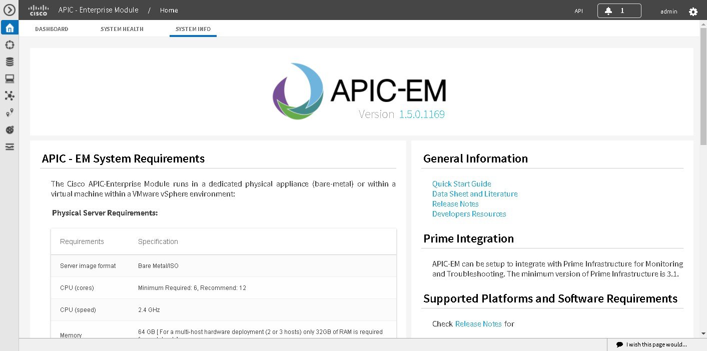
    Figure 1. SYSTEM INFO Tab


    What to Do Next

    Click on each tab and review the data provided in the GUI.

    Reviewing the SYSTEM INFO Tab

    You can use the SYSTEM INFO tab to access information at a glance about the controller, its system requirements, supported platforms, and other information. The SYSTEM INFO tab is directly accessible from the Home page.
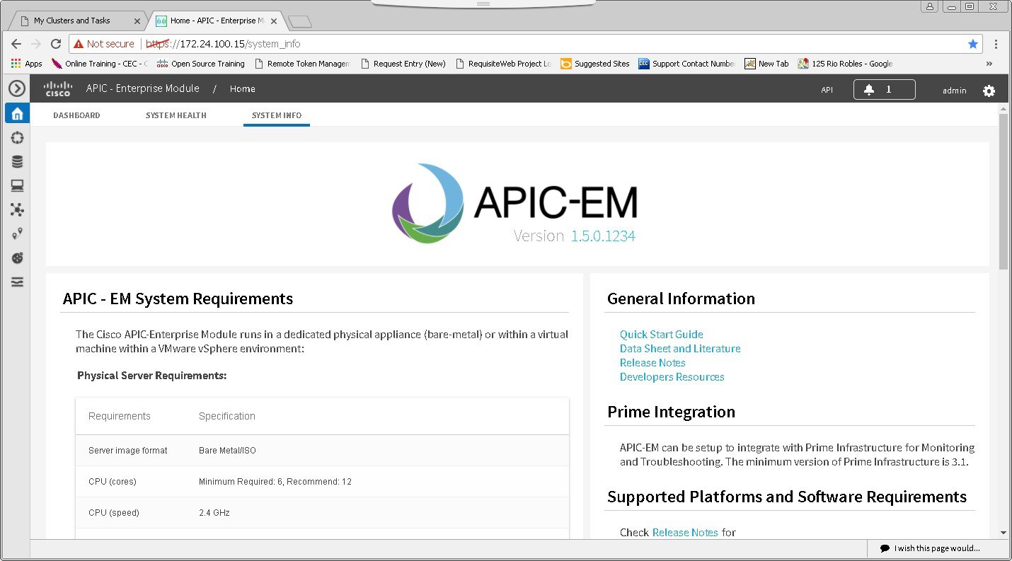
    Figure 2. SYSTEM INFO Tab

    Before You Begin

    You must have successfully deployed the Cisco APIC-EM and it must be operational.

    All users can access the contents of the SYSTEM INFO tab. The SYSTEM HEALTH tab access is limited to users with ROLE_ADMIN privileges and RBAC scope configured to All. The DASHBOARD tab is limited to users with ROLE_ADMIN privileges and RBAC scope configured to All or ROLE_POLICY_ADMIN privileges and RBAC scope configured to All.

    For information about user permissions and RBAC scopes required to perform tasks using the Cisco APIC-EM, see "User Settings" in the chapter, "Configuring the Cisco APIC-EM Settings".

    Log into the Cisco APIC-EM Home page, as described in the previous procedure.


      Step 1   On the Home page, click the SYSTEM INFO tab to view general information about the controller.

      Proceed to perform any or all of the following actions listed in the steps below.

      Step 2   Review the information displayed on the GUI page about system requirements.
      Step 3   Review the information displayed on the GUI page about supported platforms and software requirements
      Step 4   Review the information displayed on the GUI page about Prime Infrastructure support.
      Step 5   Click the link to open the Quick Start Guide.

      The Quick Start Guide provides an introduction to the controller and its basic functionality.


      What to Do Next

      Click the datasheet links or Cisco DevNet links for additional information about the controller and access to Cisco DevNet, respectively.

      Click the other tabs to review the controller's dashboard and system health.

      Reviewing the DASHBOARD Tab

      You can use the DASHBOARD tab to quickly view graphical displays of key applications on the controller and their operational status. This information can be used to monitor the controller, the network devices that the controller manages, as well as to assist in troubleshooting any problems. The DASHBOARD tab is directly accessible from the Home page.
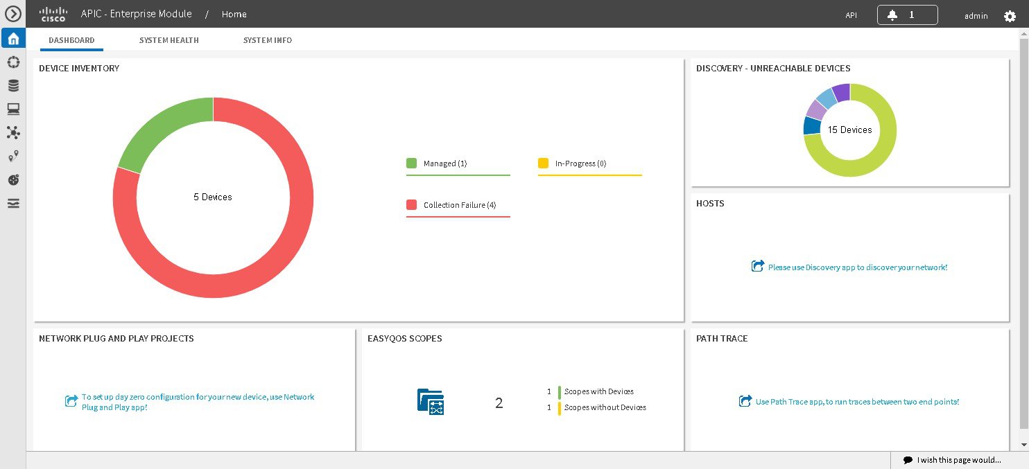
      Figure 3. DASHBOARD Tab

      Before You Begin

      You must have successfully deployed the Cisco APIC-EM and it must be operational.

      All users can access the contents of the SYSTEM INFO tab. The SYSTEM HEALTH tab access is limited to users with ROLE_ADMIN privileges and RBAC scope configured to All. The DASHBOARD tab is limited to users with ROLE_ADMIN privileges and RBAC scope configured to All or ROLE_POLICY_ADMIN privileges and RBAC scope configured to All.

      For information about user permissions and RBAC scopes required to perform tasks using the Cisco APIC-EM, see "User Settings" in the chapter, "Configuring the Cisco APIC-EM Settings".

      Log into the Cisco APIC-EM Home page, as described in the previous procedure.


        Step 1   On the Home page, click the DASHBOARD tab to view information about the controller's current activities.

        You can view data about the controller's current activities through the dashboard. This data is organized through a set of seven widgets, although only six widgets are displayed at a time.

        Note   

        A widget will not appear in the DASHBOARD tab if its underlying application has not been installed and enabled.

        Unless you have started a discovery and/or a specific controller application, the widgets in the dashboard will be grayed out and inactive. After starting a discovery, data will start to populate and appear in these widgets. Data displayed is updated every few minutes.

        Step 2   After performing a successful discovery, review the data displayed in each of the seven widgets.

        Device Inventory

        Graphical representation of the number of network devices (and percentages of network devices) being actively managed, in progress of being managed, and where there was a failure to connect to and collect device data.

        Collection failure icons in this widget are clickable and access additional data about the devices where there was a collection failure.

        Discovery-Unreachable Devices

        Graphical representation of the number of devices reachable and unreachable for a discovery.

        Clicking the circular icon in this field accesses the Discovery window for the specific discovery job.

        Branch Sites

        Graphical representation of the status of branch sites in your network for the IWAN application. This display includes the following data about branch site status:

        • Pending

        • In Progress

        • Failed

        • Provisioned

        Note   

        This widget only appears if the IWAN application is installed and enabled.

        Hosts

        Graphical representation of the hosts in your network. Display includes the number of wired and wireless hosts (and percentages of network hosts as wired or wireless).

        Note   

        This widget only appears if the IWAN application is neither installed or enabled.

        Path Trace

        Graphical representation of the successful and unsuccessful path traces.

        Clicking the circular icon in this field accesses the Path Trace window.

        EasyQoS Scopes

        Graphical representation of the policy scopes (EasyQoS) applied to the devices.

        Displays both number of policies with scopes and without scopes.

        PnP Projects

        Graphical representation of the status of Plug N Play projects for your network. This display includes the following data about PnP project status:

        • Provisioned

        • Pre-Provisioned

        • In-Progress

        • Failed

        Clicking the link in this widget launches the PnP application in the controller.

        Each widget in the above table displays data related to an application. If that widget's application is not enabled on the controller, then no data will be visible for that application.

        Step 3   Proceed to click within any widget icon to view additional detailed data about its subject matter.

        Additionally, by clicking the appropriate link within the widget you can immediately access the underlying application.


        What to Do Next

        Click the other tabs to review the controller's system health and system information.

        Reviewing the SYSTEM HEALTH Tab

        You can use the SYSTEM HEALTH tab to quickly view graphical displays of both the basic health of the system and the applications running on the controller. This information can be used to monitor the controller and its applications, as well as to assist in troubleshooting any problems. The SYSTEM HEALTH tab is directly accessible from the Home page.

        Figure 4. SYSTEM HEALTH Tab

        Before You Begin

        You must have successfully deployed the Cisco APIC-EM and it must be operational.

        All users can access the contents of the SYSTEM INFO tab. The SYSTEM HEALTH tab access is limited to users with ROLE_ADMIN privileges and RBAC scope configured to All. The DASHBOARD tab is limited to users with ROLE_ADMIN privileges and RBAC scope configured to All or ROLE_POLICY_ADMIN privileges and RBAC scope configured to All.

        For information about user permissions and RBAC scopes required to perform tasks using the Cisco APIC-EM, see "User Settings" in the chapter, "Configuring the Cisco APIC-EM Settings".

        Log into the Cisco APIC-EM Home page, as described in the previous procedure.


          Step 1   On the Home page, click the SYSTEM HEALTH tab to view information about the health of the basic system and the applications running on the controller.

          The following information is displayed in the SYSTEM HEALTH tab.

          System (Host) Health Data

          Data displayed include:

          • Host IP address

          • CPU—Host CPU usage is displayed in MHZ. Both the currently used and available host CPU is displayed.

          • Memory—Host memory usage is displayed in GB. Both the currently used and available host memory is displayed.

          • Storage—Host storage usage is displayed in GB. Both the currently used and available host storage is displayed.

          Note   

          If you have configured a multi-host cluster, then each host's data (CPU, memory, and storage) will be displayed in the UI.

          Color indicates status for the above host data:

          • Green—Indicates proper usage and support.

          • Blue—Indicates usage is approaching improper levels and triggers this warning (color change).

          • Orange—Indicates a failure based upon the usage exceeding the maximum supported value.

          Additionally, a graphical representation of the above data over the last 24 hours is displayed in this tab. Moving your cursor or mousing over the graph displays a data summation for specific date and time.

          Note   

          By placing your cursor over (mouse over) a color warning in the window, further information about the warning or failure message appears.

          Application Health Data

          Displays applications available from the Navigation pane, and the services that support each application. For example, the Topology application accessible in the GUI is supported by topology-service.

          Color bars indicate the status for the applications and the supporting service(s):

          • Green —Indicates that an application instance is starting. An application instance is the aggregation of the service instances. You can configure a minimum or maximum number of service instances, as well as grow and harvest these service instances (spin up or spin down the services).

          • Yellow—Indicates application instance and its supporting service instance(s) are experiencing issues and triggers this warning (color change).

          • Red—Indicates a failure of the application instance and its supporting service instance(s). You can harvest a service instance and then regrow it using the GUI. If the service instance does not regrow using the GUI, then you can manually regrow it. When you harvest a service instance, the controller will determine which instance is regrown (load balancing among them).

          • Blue—Indicates an in-progress state for the application or service instance (growing or harvesting).

          Step 2   Place your cursor over a specific service to view additional information about it.

          The following additional information is displayed about the service:

          • Service name

          • Service status (indicated by color code)

          • Number of instances of the service currently running

          • IP address or addresses of host where service instances are running

          • Service version

          Step 3   (Optional) Click the green-colored addition icon (+) within the service to grow (start up) an instance of that service for an application.
          Caution   

          Growing or harvesting services can be done for troubleshooting a service that is performing erratically. Be sure that you understand the possible effects of growing and harvesting services, because doing so could have unexpected results. For detailed information about growing and harvesting services for troubleshooting purposes, see the Cisco Application Policy Infrastructure Controller Enterprise Module Troubleshooting Guide.

          Step 4   (Optional) Click the red-colored subtraction icon (-) within the service to harvest (shut down) an instance of the service for an application.
          Caution   

          Growing or harvesting services can be done for troubleshooting a service that is performing erratically. Be sure that you understand the possible effects of growing and harvesting the services, because doing so could have unexpected results. For detailed information about growing and harvesting services for troubleshooting purposes, see the Cisco Application Policy Infrastructure Controller Enterprise Module Troubleshooting Guide.


          What to Do Next

          Click the other tabs to review the controller's dashboard and system information.

          Cisco APIC-EM GUI

          First GUI Window

          When you log into the Cisco APIC-EM, the GUI appears. See the following tables for descriptions of the GUI elements.
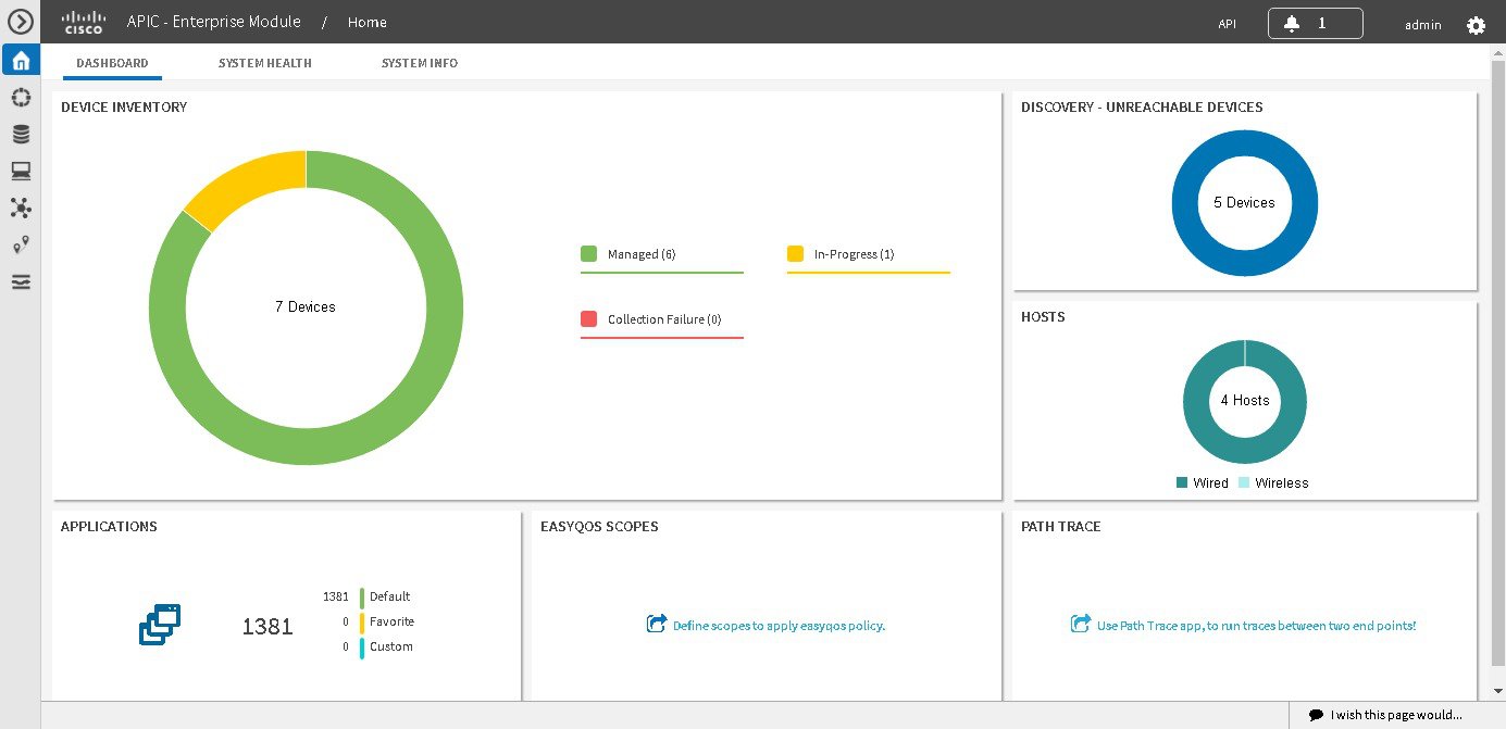


          Table 2 Cisco APIC-EM GUI Elements

          Name

          Description

          Navigation pane

          At the left side of the window, the Navigation pane provides access to the Cisco APIC-EM functions and additional applications, such as EasyQoS, Path Trace, IWAN, and Network Plug and Play.

          Global toolbar

          At the top of the window, the Global toolbar provides access to tools, such as API documentation, settings, and notifications. For a full explanation of the icons on the Global toolbar, see the Global Toolbar Options table below.

          Application or Function Pane

          In the main window area, the application or function pane displays the interface of the application or function. When you click an option in the Navigation pane or from the Global toolbar, the corresponding application or function opens in this pane.

          I wish this page would... feedback link

          At the bottom of the window, the I wish this page would... feedback link opens a preaddressed email in your email application, where you can provide input about your experience using the Cisco APIC-EM and suggestions for improvements.

          Navigation Pane Options

          The Navigation pane provides options to access the major Cisco APIC-EM features and applications.

          Table 3 Navigation Pane Options

          Icon 1

          Name

          Description

          Hide/Unhide Navigation

          Allows you to hide and unhide the Navigation pane.

          Home

          Provides information about the APIC-EM, such as its network status, system health, and system information.

          Discovery

          Allows you to configure discovery options for scanning the devices and hosts in your network.

          Device Inventory

          Provides access to the inventory database, where you can display, filter, and sort tabular information about the discovered devices in your network.

          Host Inventory

          Provides access to the inventory database, where you can display, filter, and sort tabular information about the discovered hosts in your network.

          Topology

          Presents the devices and links that the Cisco APIC-EM discovers as a physical topology map with detailed device-level data. The topology of devices and links can also be presented on a geographical map. You can use this interactive feature to troubleshoot your network.

          IWAN

          Simplifies the provisioning of IWAN network profiles with simple business policies. The IWAN application defines business-level preferences by application or groups of applications with preferred paths for hybrid WAN links. Doing so improves the application experience over any connection and saves telecommunication costs by leveraging cheaper WAN links.

          EasyQoS

          Enables you to configure quality of service on previously discovered Cisco network devices that support the EasyQoS feature. Using EasyQoS, you can group devices and then define the business relevance of applications that are used in your network. The Cisco APIC-EM takes your QoS selections, translates them into the proper command line interface (CLI) commands, and deploys them onto the selected devices.

          Path Trace

          Helps to solve network problems by automating the inspection and interrogation of the flow taken by a business application in the network.

          Network Plug and Play

          Provides a highly secure, scalable, seamless, and unified zero-touch deployment experience for customers across Cisco routers, switches and wireless access points.

          1 Other application icons may also appear in the Navigation pane depending upon the software version you are running and whether you have installed and enabled the application itself. Check the Cisco APIC-EM release notes for information about the version you have installed and supported applications.

          Global Toolbar Options

          The Global toolbar provides access to API information, administrative functions, system notifications.

          Table 4 Global Toolbar Options

          Icon

          Option

          Description

          API

          Displays the automatically generated documentation for the northbound REST APIs.

          System Notifications

          Opens the System Notifications dialog box, which provides information about system notifications that have occurred.

          The icons at the top provide a total of the number of notifications in each of the following categories:

          • Minor (yellow triangle icon)

          • Major (orange triangle icon)

          • Critical (red octagon icon)

          If notifications have occurred, they are listed below the icons. For example, any notifications about software updates or security certificates updates appear in this window.

          Click the Notification History link to open the Notifications window. This window provides information about the notification, such as its severtiy, source, timestamp, and status.

          You can perform the following actions in this window:

          • Acknowledge a notification.

          • Filter notifications by status or security level.

          • Sort notifications by source, detail, description, timestamp, or status.

          Administrative Functions

          Opens a menu of options. From this menu, you can choose the following administrative options:

          • Settings—Allows you to configure controller settings, such user profiles, discovery credentials, network security settings, backup and restore, and other controller settings.

          • App Management—Allows you to individually upload and enable Cisco and third-party applications, backup and restore the controller data, and update the Cisco APIC-EM software.

          • System Administration—Allows you to manage and troubleshoot controller services.

            Important:

            Only advanced users should access the System Administration console to attempt to troubleshoot the controller services.

          • Audit Logs—Provides information to help you monitor policy creation and application.

          • About APIC-EM—Displays the installed Cisco APIC-EM software version.

          You can perform the following user functions:

          • Change Password—Allows you to change your own password.

          • Sign Out—Logs you out of the Cisco APIC-EM.