Installing the Cisco Remote PHY Solution
Installing the Cisco GS7000 Node
For more information, see the Cisco 1.2 GHz Super High Output (SHO) GS7000 Node Installation and Operation Guide.
Opening the Cisco GS7000 Node
For more information, see the Cisco 1.2 GHz Super High Output (SHO) GS7000 Node Installation and Operation Guide.
Installing Cisco Remote PHY Device in the Cisco GS7000 Node
Procedure
| Step 1 |
Open the Cisco GS7000 node; remove all the transmitter and receiver modules (if any). |
||||||||
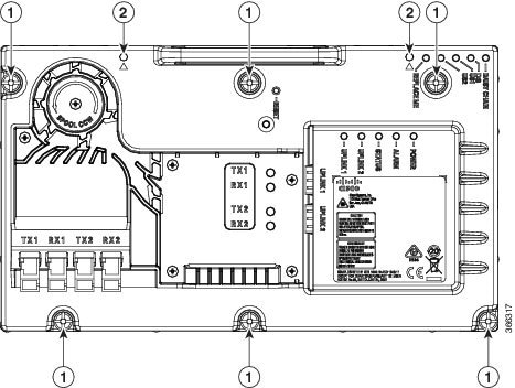
| Step 2 |
Insert the location pin on the OIB of the Cisco GS7000 node into the location hole on the Cisco RPD. Tighten the screws on the Cisco RPD with recommended torque. 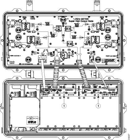
 |
||||||||
| Step 3 |
Insert the SC connector of the fiber cable into the SC adapter. Insert the LC connector of the fiber cable into the SFP+ module. The SC connector marked with “TX” on the label needs to be installed into the SC adapter marked with “TX” on top of the fiber tray. The SC connector marked with “RX” on the label needs to be installed into the SC adapter marked with “RX” on top of the fiber tray. 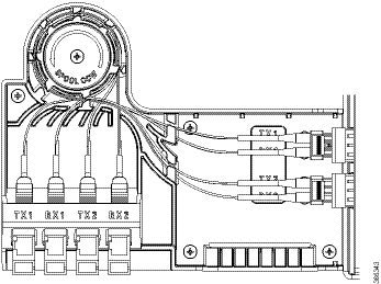 |
Setting Up Cisco Remote PHY Device on the Cisco GS7000 Node
Procedure
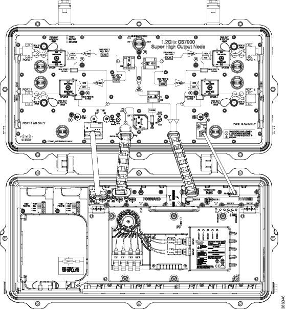
| Step 1 |
Change the Forward Control Switch in launch amp to Rphy option. |
||||||||||||||||||||||||||||||||||
| Step 2 |
Change the Reverse Control Switch to 4x1 or 4x2 based on your network. |
||||||||||||||||||||||||||||||||||
| Step 3 |
Place the ≥6dB pad at forward path and 0dB pad at reverse path on the OIB. 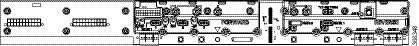
|
||||||||||||||||||||||||||||||||||
| Step 4 |
For Reverse Path (4x2 mode):
Configuration Definition
|
Powering Up the Cisco GS7000 Node
For more information, see the Cisco 1.2 GHz Super High Output (SHO) GS7000 Node Installation and Operation Guide.
Closing the Cisco GS7000 Node
For more information, see the Cisco 1.2 GHz Super High Output (SHO) GS7000 Node Installation and Operation Guide.
 Feedback