What is a Cisco cBR Series Converged Broadband Router
Introduction
The Cisco cBR Series Converged Broadband Router (Cisco cBR) is an Edge Services platform designed for cable MSOs. It supports the RF and Data-over-Cable Service Interface Specifications (DOCSIS) interfaces of a Cable Modem Termination System (CMTS) and digital optical interfaces such as Passive Optical Networks (PON) and point-to-point Ten Gigabit Ethernet.
The Cisco cBR supports video including both traditional MPEG video and Video over IP over DOCSIS (VDOC). The advantage of Cisco cBR is the ability to support MPEG video and VDOC in the same platform allowing transition from MPEG to VDOC. The Cisco cBR is a single device that manages the entire RF spectrum of the cable plant.
The Cisco cBR provides high-speed data, broadband, and IP telephony services to residential and commercial subscribers using cable modems or digital set-top boxes (STBs). It supports data and digitized voice connectivity over a bidirectional cable television and IP backbone network. And uses advanced quality of service (QoS) techniques to ensure that real-time traffic such as voice can be reliably delivered, while still transmitting other traffic on a best-effort basis.
The Cisco cBR concentrates traffic from two-way DOCSIS-based cable modems and STBs that is transmitted over the coaxial cable television (CATV) network, and presents that traffic to local and remote Internet Protocol (IP) hosts over its high-speed network uplink interfaces.
The Cisco cBR runs on the Cisco IOS-XE networking software and supports the most advanced networking and routing options.
Functional Overview
-
High speed data access over DOCSIS
-
Video over DOCSIS
-
Voice services over DOCSIS
-
Business services over DOCSIS
-
MPEG transport-based video distribution
-
Videoscape management system integration
-
Data plane optimization to carry ABR traffic including monitoring of quality of service
-
Assistance with the support of legacy devices in a Videoscape environment
-
Video cache integration
The path from the Cisco CMTS to the cable modem or STB is the downstream, which carries the majority of traffic over the cable interface.
The path from the cable modem or STB to the Cisco CMTS is the upstream, and it carries approximately 10 percent of the traffic that is sent over the downstream.
A large number of users can be assigned to the same downstream, and for efficient use of bandwidth, those users can be split among several different upstream.
The following sections contain information about:
Upstream Data Path
The following example describes the upstream data path.
-
A request for service is generated by a subscriber. The modem transmits the request as a series of packets to the Cisco CMTS on the upstream.
-
The cable line card receives the packets on its upstream interface and forwards them to its onboard processor.
-
The line card processor verifies the header check sequence (HCS), frame check sequence (FCS), and system identification number (SID), processes all fields in the DOCSIS MAC header, and then removes the header.
-
The line card examines and processes the extended headers (Request, Acknowledgment, Privacy, PHSs and Unsolicited Grand Synchronization header elements). If Baseline Privacy Interface (BPI) is used, the processor also decrypts the Privacy EH frames using the appropriate key.
-
Bandwidth requests, acknowledgment (ACK) requests, and unsolicited grant syncs are reformatted and passed to the request ring of the Cisco cable line card.
-
The DOCSIS MAC header is removed and another header is added, which includes the SID, the upstream port information, and status bits that indicate whether any errors were detected.
-
-
The packet is sent across the backplane to the forwarding processor (FP) or the routing processor (RP) on the route processor.
-
The route processor performs packet operations such as access list processing, classification, switching, and QoS. It is also where major routing and IOS management functions (filtering) are run.
-
The packet is moved to the correct output queue and transmitted over the backplane to the network uplink card (Ten Gigabit Ethernet) or another cable interface line card.
-
The output card forwards the packet to the next interface point.
Downstream Data Path
The following example describes the downstream data path.
-
Data packets from the Internet are received by the network uplink cards (Ten Gigabit Ethernet).
-
The packets are forwarded to the forwarding processor (FP) on the Supervisor module.
-
The FP performs MAC classification to determine the type of frame or packet to be processed.
-
The route processor performs access list filtering, policing, and marking.
-
The route processor performs a forwarding information base (FIB) lookup and rewrite.
-
The rewrite consists of a downstream header and 802.3 MAC header.
-
The downstream header contains destination primary SID, physical DS port number, PHS rule index, and some control bits and other fields.
-
The packet is policed, shaped, and prepared for queueing. Queueing is based on the priority of the queue and the state of the flow bits from the card. The destination card address (port) is pre-appended on the header of the packet being transmitted.
-
-
The packet is transmitted over the backplane to the appropriate cable interface line card.
-
The cable interface line card receives the packet and forwards it to all the ASICs on the line card.
-
Each ASIC decodes the header to determine if the packet is destined for one of the downstream ports on that card. If so, the downstream header is removed and the 802.3 MAC header is saved.
-
The MAC header is processed to determine how to build the DOCSIS MAC header and what operations to perform on the packet. These might include pre-appending the DOCSIS MAC header, computing the HCS and FCS, performing Packet Header Suppression, and BPI encryption.
-
-
After the packet is ready, it is immediately transmitted on the downstream.
Cisco cBR-8 Converged Broadband Router
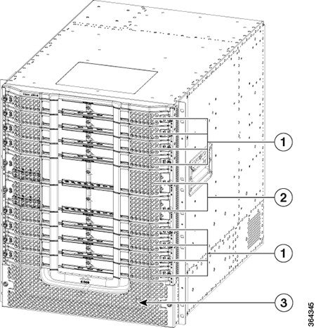
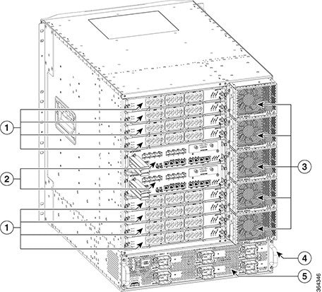
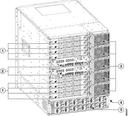
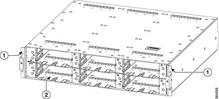
The Cisco cBR-8 Converged Broadband Router (Cisco cBR-8) is a 13 rack unit (RU) chassis. It supports multiple card modules and is designed with back-to-back midplanes; a front facing Digital Midplane and a rear facing RF Midplane.
The front card modules plug into the Digital Midplane and the associated Physical Interface Card (PIC) plugs into the rear of the chassis. All permanent connections to the Cisco cBR-8 chassis are made at the rear.
|
1 |
Line Cards |
3 |
Front Power Entry Bezel |
|
2 |
Supervisor Cards |
|
1 |
Line Card PIC |
4 |
Lifting Handle |
|
2 |
Supervisor PIC |
5 |
AC FPEM |
|
3 |
Fan Module |
|
1 |
Line Card PIC |
4 |
Lifting Handle |
|
2 |
Supervisor PIC |
5 |
DC FPEM |
|
3 |
Fan Module |
The Cisco cBR-8 chassis supports:
-
Two Supervisor Cards
-
Two Supervisor PICs
-
Eight Cisco cBR line cards
-
Eight Cisco cBR RF PIC cards (seven when the chassis is configured in protect mode) or Eight Cisco cBR DPIC cards (if -R line cards are installed)
-
One Cisco cBR RF PROT PIC card (if the chassis is configured in RF protect mode)
-
Six DC Power Modules with redundant input feeds or six AC Power Modules
-
One Cisco cBR DC FPEM or one Cisco cBR AC FPEM
-
Five Fan Modules
Physical Description
| Parameter | Description |
|---|---|
|
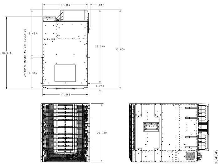
Height |
13RU (22.75 in./57.78 cm) |
|
Width |
17.45 in. (44.32 cm) without rack mounts 17.65 in. (44.83 cm) with rack mounts |
|
Overall Depth |
28.075 in. (71.3 cm) |
|
Weight |
429 lb (195 kg) maximum fully loaded |
|
Airflow |
Front-to-back |
Cisco cBR-8 Chassis Dimensions
The below image shows the basic dimensions of the Cisco cBR-8 chassis.
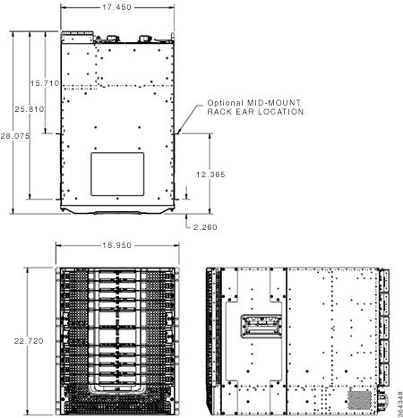
The below image shows the overall dimensions of the Cisco cBR-8 chassis with optional cable management and rear door cable protection.
Cisco cBR-8 Chassis Features
Digital Midplane
The Digital Midplane provides connectivity between various components in the chassis. It provides the interconnect between the supervisors and all the interface slots. This interconnect includes differential pairs used for ESI data plan links, Gigabit Ethernet/Ten Gigabit Ethernet control plane links, timing and single-ended signals used for status and control functions. It also has connections for status and control of PICs, the power shelf, and the fan modules.
RF Midplane
The RF midplane interconnects all RF-capable slots to allow backup RF line cards to send and receive RF signals to and from an active RF line card PIC. It is designed to support a maximum of 24 RF ports on a PIC with all ports carrying signals with frequency content up to 1.2 GHz. It supports downstream, upstream, and a mixture of both.
Rear Door (Optional)
The rear door provides protection to the PIC cables.
Lifting Handles
The Cisco cBR-8 chassis has four handles available for lifting. It is recommended to remove all circuit cards before attempting to install the chassis in a rack, but at a minimum, the front Supervisors and line cards should be removed before lifting the chassis with the available handles.
The accessory kit that ships with the chassis includes rack mount rails. These can be pre-assembled in the rack to help slide the chassis into place. An optional front mounted lifting handle is also available to help with chassis installation.
Rear Cable Connectivity
All permanent facility cabling is on the rear of the chassis. Connectors on the PICs provide connectivity to the front mounted Supervisors and line cards.
Front Side LED and Temporary I/O Locations
The LEDs are situated at the lower middle area on all the front mounted cards. Temporary I/O connectivity ports are available on the left side of the Supervisor Card behind a removable door in the ejector handle.
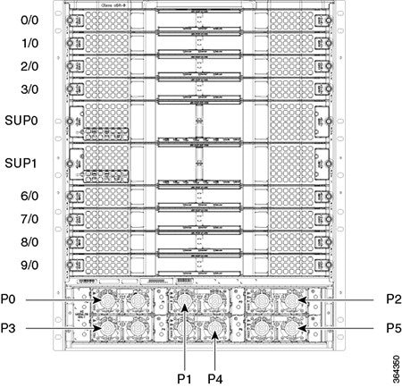
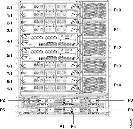
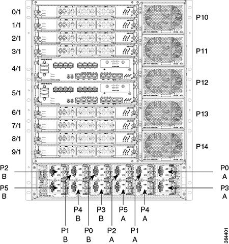
Slot Numbering—Physical and Logical
|
Component |
Slot Numbering |
|---|---|
|
Front and Rear Circuit Cards |
Identified by a two number system. The numbers are separated by a forward slash.
|
|
Supervisor Cards |
Identified as SUP0 and SUP1. |
|
Power Supply Modules |
Numbered from P0 to P5 and these map to the facility power outlet markings on the rear of the chassis. |
|
Fan Modules |
Numbered from P10 (the top fan module slot) to P14 (the bottom fan module slot). |

|
Variable |
Component |
Description |
Valid Range/Values |
|---|---|---|---|
|
Release—Cisco IOS-XE Release 3.15.0S |
|||
|
Slot |
Interface card |
Slot where the interface card resides. |
0 to 3 and 6 to 9 |
|
Supervisor card |
Slot where the Supervisor card resides. |
4 or 5 |
|
|
Subslot |
Interface card |
Secondary slot where the interface card resides. |
0 |
|
Supervisor card |
Secondary slot where the Supervisor card resides. |
1 |
|
|
Port |
Interface card (downstream) |
Downstream controller port on the interface card. |
0 to 7 |
|
Interface card (upstream) |
Upstream controller port on the interface card. |
0 to 15 |
|
|
Supervisor card |
Controller port on the Supervisor card. |
0 to 7 (For Ten Gigabit Ethernet ports) |
|
|
cable-interface-index |
Interface card |
MAC domain index of the interface card. |
0 to 15 |
|
logical-channel-index |
NA |
NA |
NA |
|
rf-channel |
Interface card (downstream) |
RF channel number on the interface card. |
0 to 159 |
|
Interface card (upstream) |
RF channel number on the interface card. |
0 to 11 |
|
|
Supervisor card |
RF channel number on the Supervisor card. |
NA |
|
|
wideband-channel |
Interface card |
Wideband channel number on the interface card. |
0 to 63 |
|
Supervisor card |
Wideband channel number on the Supervisor card. |
NA |
|
Field Replaceable Units
|
Hardware Module |
Function Description |
|---|---|
|
Supervisor (SUP) |
The route and forwarding processor of the system and includes integrated backhaul capability. |
|
Supervisor PIC |
Provides the supervisor physical interface to the facility located on these cards. |
|
Subscriber Side Interface Card (SSI Card) |
Provides the service side functionality such as DOCSIS, Edge QAM, EPON, or other service blades. |
|
SSI PIC |
Provides the physical interface to the facility for the SSI Cards. |
|
Power Modules (AC or DC) |
Provide power conversion, filtering, and conditioning from facility input power to the required -52V midplane power that is used within the chassis. There are specific AC and DC modules depending on the facility input voltage. The power modules provide their own cooling using internal fans. |
|
Facility Power Entry Module (FPEM) (AC/DC) |
Provides the physical hookup interface and interconnection to the power modules for either the AC or DC input voltage. The digital communication from the power modules to the digital midplane; and the power interconnect from the power modules to the midplane Bus Bar. This module is field replaceable to allow the facility to change from AC to DC or DC to AC in the future without having to replace the chassis. |
|
Power Cassette Module |
Provides the physical support and keying for the power supply modules. It is keyed with a corresponding FPEM to determine AC or DC support. |
|
Fan Module |
Provides forced air cooling for the front and rear card slots. |
|
Slot Type |
Quantity and Pitch |
|---|---|
|
Supervisor Slots |
2 in the front of chassis on a 2.75” pitch |
|
Supervisor PIC Slots |
2 in the rear of chassis on a 2.75” pitch |
|
SSI Card Slots |
8 in the front of chassis on a 1.48” pitch |
|
SSI PIC Slots |
8 in the rear of chassis on a 1.48” pitch |
|
Power Cassette Module |
6 power supply bays in the front of the chassis |
|
Facility Power Entry Module (FPEM) (AC/DC) |
1 in the bottom, rear of the chassis |
|
Fan Module |
5 in the rear of the chassis on a 3.5” pitch |
|
Module |
Maximum Weight |
|---|---|
|
Supervisor Slots |
26 lbs. |
|
Supervisor PIC Slots |
6 lbs. |
|
SSI Card Slots |
19 lbs. |
|
NSI/SSI Slots |
19 lbs. |
|
SSI PIC Slots |
5 lbs. |
|
NSI/SSI PIC Slots |
5 lbs. |
|
Power Cassette Module |
6 lbs. |
|
Power Cassette (AC/DC) |
17 lbs. |
|
Facility Power Entry Module (FPEM) (AC/DC) |
15 lbs. |
|
Fan Module |
4 lbs. |
|
13RU Chassis Estimated Weight (with midplanes and Bus Bar) |
85 lbs.1 |
|
13RU Loaded Chassis Estimated Weight (maximum) |
429 lbs. |
|
Module |
Maximum Power Allocated (Watts) |
|---|---|
|
Supervisor Slots |
930 |
|
Supervisor PIC Slots |
120 |
|
SSI Card Slots |
530 |
|
SSI PIC Slots |
60 |
|
Fan Module |
170 |
|
Bus Bar + Midplane Loss |
150 |
|
cBR-8 Total Power Allocation (power to Bus Bar from FPEM) |
7820 |
|
cBR-8 Facility Power Requirement |
9000 |
|
Module |
Envelope Size (width x height x depth) |
|---|---|
|
Supervisor Card |
17.24” x 2.75” x 19.99” |
|
Supervisor PIC |
11.80” x 2.75” x 7.82” |
|
SSI Card |
17.24” x 1.48” x 19.99” |
|
SSI PIC |
11.80” x 1.48” x 7.82” |
|
Fan Module |
5.16” x 3.50” x 8.39” |
|
AC FPEM |
17.45” x 3.85” x 10.08” |
|
DC FPEM |
17.45” x 3.85” x 10.08” |
|
AC Power Supply Module |
4.00” x 1.60 x 16.94” |
|
DC Power Supply Module |
4.00” x 1.60 x 16.94” |
|
Power Cassette Module |
17.3" x 3.7" X 16.9" |
Supervisor
Cisco cBR-8 Converged Cable Access Router Supervisor 250G
The Cisco® cBR-8 Converged Cable Access Router Supervisor 250G perform the data forwarding and routing processing functions of carrier-class and high performance cBR-8 Converged Cable Access Router. Not only does the supervisor provide advanced routing capabilities, but it also monitors and manages other components in the Cisco® cBR-8 Converged Cable Access Router. The supervisor consists of two FRU (Field Replaceable Unit): Supervisor and Supervisor PIC (Physical Interface Card). Supervisor PIC card has all the physical interface ports and related PHY component on board.
As the management processor for the Cisco® cBR-8 Converged Cable Access Router, the supervisor also performs the following management functions: chassis management including activation and initialization of the other cards, selection/switchover of active vs. standby cards, image management and distribution, logging facilities, distribution of user configuration information, monitor and manage the power and temperature of system components such as line cards, power supplies, and fans, provide out-of-band system console and auxiliary ports, USB, and Ethernet ports for router configuration and maintenance etc. Supervisor works together with SUP PIC offering below main features:
-
Provides up to 250Gbps Downstream and Upstream aggregated forwarding capacity
-
Flexible data path interconnection between active and standby supervisors to support a total of 2x100G worth of active-active backhaul bandwidth
-
Integrate full range of industry-leading Cisco IOS® Software features and services
-
SSD memory (240G) for syslog/debug information/image/package storage
-
Run with the modular Cisco IOS XE Software for the Cisco® cBR-8 Converged Cable Access Router
-
Provide 1+1 redundant-supervisor support
-
Two Integrated 1x100G NSI (Network Side Interface) backhaul interfaces on Supervisor PIC. The interface can support either QSFP28 or QSFP+ module
-
Two RJ45 GE network management ports are hardware capable of supporting Synchronous Ethernet
-
High Availability: 1+1 active/active NSI or iNSI interface redundancy, 1+1 DTI client (PIC) redundancy, 1+1 network timing redundancy (DOCSIS, PTP, Synchronous Ethernet)
-
Offer field-replaceable and hot-swappable capabilities to help ensure minimal service disruption
The Cisco cBR-8 supports:
-
Two Supervisor Cards
-
Two Supervisor PICs
Supervisor Card
The Supervisor Card is the route processor of the Cisco cBR and includes integrated backhaul capability. It is installed in the front of the Cisco cBR chassis. The plastic latch maintains the alignment of the spring-loaded ejector with the faceplate. The Supervisor Card has a tethered door to allow access to the ports on its faceplate.
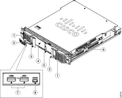
|
1 |
Spring-loaded ejector |
5 |
LEDs |
|
2 |
Tethered I/O door |
6 |
Support rails |
|
3 |
Plastic latch |
7 |
USB ports |
|
4 |
Removable air filter |
8 |
Console port |
|
Unit |
Value |
|---|---|
|
Depth |
19.98 in (50.7 cm) |
|
Width |
16.27 in (41.3 cm) |
|
Height |
2.82 in (7.16 cm) |
|
Maximum weight |
26 lb (11.8 kg) |
|
Port |
Description |
|---|---|
|
USB ports |
The Supervisor Card has two type-A USB ports. These ports are used for connecting external memory sticks or flash drives to load configurations. |
|
Console port |
The Supervisor Card has one mini type-B USB console port. This port is an asynchronous EIA/TIA-232 serial port used to connect a terminal to the Supervisor Card for local administrative access. |
 Note |
The ports on the Supervisor Card are used for temporary connections. For all permanent connections, including the console connection, you must use the ports on the Supervisor PIC installed in the rear of the chassis. |
The Supervisor Card has the following LEDs:
|
LED |
Description |
|---|---|
|
PWR STAT |
Power status LED |
|
RP STAT |
RP status LED |
|
RP ACT |
RP active LED |
|
FP STAT |
FP status LED |
|
FP ACT |
FP active LED |
|
INSI ACT |
iNSI active LED |
|
ALRM |
Alarm LED |
|
RPLC |
Replace LED |
Important |
Different Supervisor Cards cannot coexist on a Cisco cBR-8 router. We recommend that you install the Supervisor Cards with the same capacity in the chassis to ensure proper redundancy support. |
Supervisor PIC
The Supervisor PIC provides the physical interface to the Supervisor Card. It is installed in the rear of the Cisco cBR chassis.
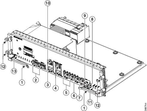
|
1 |
Ejector lever |
8 |
Timing port (1 PPS) |
|
2 |
QSFP ports |
9 |
Timing port (10 MHz) |
|
3 |
Auxiliary port |
10 |
Console port |
|
4 |
DTI ports |
11 |
LEDs |
|
5 |
NME ports |
12 |
Captive screws |
|
6 |
CM/DTP port |
13 |
10G LED |
| 7 |
TOD port |
|
Unit |
Value |
|---|---|
|
Depth |
8.1 in (20.6 cm) |
|
Width |
11.79 in (29.9 cm) |
|
Height |
2.82 in (7.16 cm) |
|
Maximum weight |
3.44 lb (1.56 kg) |
|
Port |
Description |
|---|---|
|
QSFP ports |
The Supervisor PIC has two QSFP ports. These ports are used to connect it to the switch or router. These ports provide backhaul connection to the WAN network. |
|
Timing ports |
The Supervisor PIC has two timing ports, 1 PPS and 10 MHz ports, which are reserved for future use. |
|
TOD port |
The Supervisor PIC has a Time of Date (ToD) port. |
|
DTI ports |
The Supervisor PIC has two DTI ports. These ports are used for connecting to DTI server as a reference clock source. |
|
CM/DTP port |
The Supervisor PIC has a CM/DTP port, which is reserved for future use. |
|
NME ports |
The Supervisor PIC has two NME ports. These ports are the Gigabit Ethernet management ports. One port is used for network management and is used to connect to a switch and the other port is reserved for future use. |
|
Console port |
The Supervisor PIC has one RJ-45 console port. This port is an asynchronous EIA/TIA-232 serial port used to connect a terminal to the Supervisor PIC for local administrative access. |
|
Auxiliary port |
The Supervisor PIC has one auxiliary port. This port is used to connect a terminal server to the Supervisor PIC for verifying the system status. |
The Supervisor PIC has the following LEDs:
|
LED |
Description |
|---|---|
|
PIC_STAT |
Supervisor PIC status LED |
|
INSI_ACT |
iNSI active LED |
|
REPLACE |
Replace LED |
|
SFP+ |
SFP+ module and link status LED |
|
DTI Normal |
DTI normal mode status LED |
|
DTI Fast |
DTI fast mode status LED |
|
NME Lnk |
NME module link status LED |
|
NME Act |
NME module link active LED |
|
SSD |
SSD access status LED |
|
CM/DTP Lnk |
Reserved for future use |
|
CM/DTP Act |
Reserved for future use |
Cisco cBR-8 Converged Cable Access Router Supervisor 160G
The Supervisor is the processor of the Cisco cBR. It consists of a forward processor (FP) complex and route processor (RP) complex.
The FP complex performs data forwarding, baseline router packet operations including MAC classification, Layer 2 and the various Layer 3 forwarding, QoS classification, security ACLs, VPNs, policing, shaping, load balancing, and Netflow, egress packet buffering, queueing, and egress packet scheduling functions. The FP complex supports firewall, intrusion prevention, Network-Based Application Recognition (NBAR), Network Address Translation (NAT), flexible pattern matching, tunneling protocols, and header and payload compression.
The RP complex performs route processing, Cisco cBR chassis management, and runs the network operating system and its controls.
The Supervisor supports:
-
Eight Ten Gigabit Ethernet backhaul interfaces.
-
1+1 active/standby redundancy.
-
Chassis management of the Cisco cBR including activation and initialization of the other cards, selection and switch over of the active and standby cards, image management and distribution, logging facilities, distribution of user configuration information .
-
DOCSIS Timing Interface (DTI) client and server ports.
-
Online insertion and removal (OIR).
The Supervisor consists of the following field replaceable units (FRUs):
-
Supervisor Card
-
Supervisor physical interface card (PIC)
The Cisco cBR-8 supports:
-
Two Supervisor Cards
-
Two Supervisor PICs
Supervisor Card
The Supervisor Card is the route processor of the Cisco cBR and includes integrated backhaul capability. It is installed in the front of the Cisco cBR chassis. The plastic latch maintains the alignment of the spring-loaded ejector with the faceplate. The Supervisor Card has a tethered door to allow access to the ports on its faceplate.

|
1 |
Spring-loaded ejector |
5 |
LEDs |
|
2 |
Tethered I/O door |
6 |
Support rails |
|
3 |
Plastic latch |
7 |
USB ports |
|
4 |
Removable air filter |
8 |
Console port |
|
Unit |
Value |
|---|---|
|
Depth |
20 in (50.8 cm) |
|
Width |
17.2 in (43.68 cm) |
|
Height |
2.8 in (7.11 cm) |
|
Maximum weight |
26 lb (11.79 kg) |
|
Port |
Description |
|---|---|
|
USB ports |
The Supervisor Card has two type-A USB ports. These ports are used for connecting external memory sticks or flash drives to load configurations. |
|
Console port |
The Supervisor Card has one mini type-B USB console port. This port is an asynchronous EIA/TIA-232 serial port used to connect a terminal to the Supervisor Card for local administrative access. |
Note |
The ports on the Supervisor Card are used for temporary connections. For all permanent connections, including the console connection, you must use the ports on the Supervisor PIC installed in the rear of the chassis. |
The Supervisor Card has the following LEDs:
|
LED |
Description |
|---|---|
|
PWR STAT |
Power status LED |
|
RP STAT |
RP status LED |
|
RP ACT |
RP active LED |
|
FP STAT |
FP status LED |
|
FP ACT |
FP active LED |
|
INSI ACT |
iNSI active LED |
|
ALRM |
Alarm LED |
|
RPLC |
Replace LED |
The router supports the following Supervisor Cards:
-
CBR-CCAP-SUP-60G—Supervisor Card with 60 Gbps forwarding capacity. It supports a maximum of four interface cards, working in 3+1 protection mode, on the Cisco cBR-8 router. It supports a maximum of 72268 unicast flows or 88268 modular quality of service (MQoS) flows. The maximum number of unicast and MQoS flows supported is 88268.
Note
If you are using the CBR-CCAP-SUP-60G Supervisor Card in Cisco IOS-XE Release 3.15.0S, the output of the show inventory command displays the CBR-CCAP-SUP-160G PID instead of the CBR-CCAP-SUP-60G PID.
-
CBR-CCAP-SUP-160G—Supervisor Card with 160 Gbps forwarding capacity. It supports a maximum of eight interface cards, working in N+1 protection mode, on the Cisco cBR-8 router.
Important |
Different Supervisor Cards cannot coexist on a Cisco cBR-8 router. We recommend that you install the Supervisor Cards with the same capacity in the chassis to ensure proper redundancy support. |
Supervisor PIC
The Supervisor PIC provides the physical interface to the Supervisor Card. It is installed in the rear of the Cisco cBR chassis.
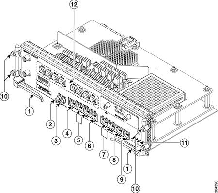
|
1 |
Ejector lever |
7 |
NME ports |
|
2 |
Timing port (1 PPS) |
8 |
Console port |
|
3 |
Timing port (10 MHz) |
9 |
Auxiliary port |
|
4 |
GPS port |
10 |
Captive screws |
|
5 |
DTI ports |
11 |
LEDs |
|
6 |
CM/DTP port |
12 |
SFP+ ports |
|
Unit |
Value |
|---|---|
|
Depth |
7.82 in (19.86 cm) |
|
Width |
11.8 in (29.97 cm) |
|
Height |
2.8 in (7.11 cm) |
|
Maximum weight |
6 lb (2.72 kg) |
|
Port |
Description |
|---|---|
|
SFP+ ports |
The Supervisor PIC has eight Ten Gigabit Ethernet SFP (SFP+) ports. These ports are used to connect it to the switch or router. These ports provide backhaul connection to the WAN network. |
|
Timing ports |
The Supervisor PIC has two timing ports, 1 PPS and 10 MHz ports, which are reserved for future use. |
|
GPS port |
The Supervisor PIC has a GPS port, which is reserved for future use. |
|
DTI ports |
The Supervisor PIC has two DTI ports. These ports are used for connecting to DTI server as a reference clock source. |
|
CM/DTP port |
The Supervisor PIC has a CM/DTP port, which is reserved for future use. |
|
NME ports |
The Supervisor PIC has two NME ports. These ports are the Gigabit Ethernet management ports. One port is used for network management and is used to connect to a switch and the other port is reserved for future use. |
|
Console port |
The Supervisor PIC has one RJ-45 console port. This port is an asynchronous EIA/TIA-232 serial port used to connect a terminal to the Supervisor PIC for local administrative access. |
|
Auxiliary port |
The Supervisor PIC has one auxiliary port. This port is used to connect a terminal server to the Supervisor PIC for verifying the system status. |
The Supervisor PIC has the following LEDs:
|
LED |
Description |
|---|---|
|
PIC_STAT |
Supervisor PIC status LED |
|
INSI_ACT |
iNSI active LED |
|
REPLACE |
Replace LED |
|
SFP+ |
SFP+ module and link status LED |
|
DTI Normal |
DTI normal mode status LED |
|
DTI Fast |
DTI fast mode status LED |
|
NME Lnk |
NME module link status LED |
|
NME Act |
NME module link active LED |
|
SSD |
SSD access status LED |
|
CM/DTP Lnk |
Reserved for future use |
|
CM/DTP Act |
Reserved for future use |
Interface Cards
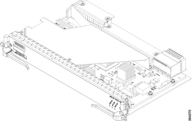
The Subscriber Side Interface (SSI) card (line card) provides the DOCSIS MAC or DOCSIS MAC/PHY function in the Cisco cBR router.
The front of the line card has spring-loaded ejectors with plastic latches, on both sides of the interface line card. The plastic latch maintains the spring-loaded ejector's alignment with the faceplate.
The line cards have perforated grill faceplate that allow air flow into the card. There is a removable filter in the front panel of the line card. This filter filters the air flowing into the chassis through the perforated grill faceplate.
All interface cards in the Cisco cBR-8 chassis are designed for High Availability (HA) with a N+1 redundancy scheme. The Cisco cBR-8 supports the following interface cards:
-
Interface Line Card (SSI Card, DOCSIS MAC or DOCSIS MAC/PHY line card)—Provides the service side functionality such as DOCSIS, Edge QAM, EPON, or other service blades.
-
RF Through PIC or Digital Through PIC—Connects to the interface line card. This PIC provides the physical interface to the facility for the line card.
-
RF Protect PIC or Digital Protect PIC—Provides connection of the redundant line card to the appropriate Through PIC.
A DOCSIS MAC/PHY line card is paired with an RF Physical Interface Card (RF Through PIC or RF Protect PIC).
A DOCSIS MAC line card is paired with an Digital Interface Card (DPIC).
The Cisco cBR chassis supports the following SSI Cards:
-
DOCSIS MAC/PHY SSI Card with two downstream D3.1 modules and one upstream D3.1 module installed. [PID: CBR-LC-8D31-16U31]
-
DOCSIS MAC/PHY SSI Card with one downstream D3.1 modules and one upstream D3.1 module installed. [PID: CBR-LC-4D31-16U31]
-
DOCSIS MAC/PHY SSI Card with two downstream D3.0 modules and one upstream D3.0 module installed. [PID: CBR-LC-8D30-16U30]
-
DOCSIS MAC SSI Card (40Gbps). [PID: CBR-CCAP-LC-40G-R]
-
DOCSIS MAC SSI Card (80Gbps). [PID: CBR-CCAP-LC-80G-R]

|
1 |
Plastic latch |
3 |
LEDs |
|
2 |
Removable Filter |
4 |
Spring-loaded ejector |
|
Unit |
Value |
|---|---|
|
Depth |
20 in (50.8 cm) |
|
Width |
17.2 in (43.7 cm) |
|
Height |
1.5 in (3.8 cm) |
|
Maximum Weight |
19 lbs (8.61 kg) |
|
Ports |
Description |
|---|---|
|
Downstream ports |
The SSI Card has 8 downstream ports. These ports support downstream DOCSIS and MPEG traffic on the downstream PHY modules. |
|
Upstream DOCSIS ports |
The SSI Card has 16 upstream DOCSIS ports. These ports support upstream DOCSIS traffic on the upstream PHY module. |
The line card has the following LEDs:
|
LED |
Description |
|---|---|
|
STATUS |
Status of the card. |
|
PROTECT |
Protect configuration status of the card. |
|
REPLACE |
Indicates if the card must be replaced. |
Interface Line Card Blank
Apart from the operational interface line cards, an interface line card blank (line card blank) is installed in any empty unused line card slot, to ensure proper airflow within the operational chassis.
Protect Zone
To configure N+1 RF redundancy, the interface line card installed in the uppermost slot is configured as the Protect line card with the Protect PIC installed in the corresponding PIC slot. The working line cards and the Through PIC cards installed successively below the Protect line card and PIC card form a Protect Zone. The following are the restrictions for the Protect Zone:
-
Each protect zone has one Protect PIC card at the top with a set of Through PIC cards installed successively below the protect line card.
-
A PIC card blank should not be installed within a protect zone. It is not necessary to have a line card in every slot of a protect zone.
-
If another line card is configured as a Protect line card, then it forms a separate Protect Zone with the successive working line cards below it.
-
Every Protect line card must have an Protect PIC installed in the corresponding PIC slot in the rear of the chassis.
Downstream PHY Module
Each interface line card supports two downstream PHY modules. The Cisco cBR chassis supports the following downstream PHY module versions:
-
Downstream D3.0 (supporting DOCSIS 3.0). [PID: CBR-D30-DS-MOD]
-
Downstream D3.1 (supporting DOCSIS 3.1). [PID: CBR-D31-DS-MOD]
Note |
The Downstream D3.1 module has a green label on it. |
The following limitations are applicable to the downstream PHY modules:
-
All interface line cards in the chassis must have the same downstream PHY module version; that is all D3.0 or D3.1 modules.
-
In an interface line card, both the downstream PHY modules must be the same version; that is both D3.0 or both D3.1 modules.
-
The downstream D3.1 modules are supported only with the Cisco IOS-XE Release 3.16.0S and later releases.
-
If the downstream D3.1 modules are installed with the Cisco IOS-XE Release 3.15.0S, the downstream D3.1 modules will boot up, but not function properly.
-
With the Cisco IOS-XE Release 3.16.0S, the downstream D3.1 module provides operational readiness for the implementation of DOCSIS 3.1 functions and features.
Upstream PHY Module
Each interface line card supports one upstream PHY module. The Cisco cBR chassis supports the following upstream PHY module versions:
-
Upstream D3.0 (supporting DOCSIS 3.0). [PID: CBR-D30-US-MOD]
-
Upstream D3.1 (supporting DOCSIS 3.1). [PID: CBR-D31-US-MOD]
Note |
The Upstream D3.1 module has a green label on it. |
The following limitations are applicable to the upstream PHY modules:
-
All interface line cards in the chassis must have the same upstream PHY module version; that is all D3.0 or D3.1 modules.
-
The upstream D3.1 module is supported only with the Cisco IOS-XE Release 3.18.0S and later releases.
-
If the upstream D3.1 modules are installed with the Cisco IOS-XE Release 3.17.0S, the upstream D3.1 modules will boot up, but not function properly.
-
With the Cisco IOS-XE Release 3.18.0S, the upstream D3.1 module provides operational readiness for the implementation of DOCSIS 3.1 functions and features.
RF PICs
The RF PICs are installed into the rear of the Cisco cBR chassis.
-
RF Through PIC
-
RF Protect PIC
RF Through PIC
The RF Through PIC connects to the line cards on the digital and RF midplanes, and provides downstream and upstream physical connectivity. It connects to the DOCSIS MAC/PHY line card.
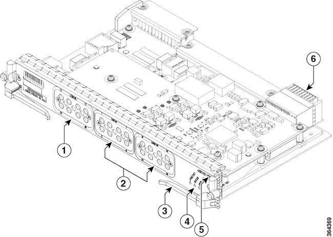
|
1 |
Downstream ports DS0 to DS7 |
4 |
LEDs |
|
2 |
Upstream ports US0 to US7 and US8 to US15 |
5 |
Product Identifier (PID) |
|
3 |
Ejector Lever |
|
Unit |
Value |
|---|---|
|
Depth |
7.8 in (19.8 cm) |
|
Width |
11.8 in (30 cm) |
|
Height |
1.5 inch (3.8 cm) |
|
Maximum Weight |
5 lbs (2.26 kg) |
|
Ports |
Description |
|---|---|
|
DS0 to DS7 |
The RF Through PIC has eight 50-1200 MHz RF connector ports that provide downstream channel connectivity. |
|
US0 to US7 and US8 to US15 |
The RF Through PIC has sixteen 5-204 MHz RF connector ports that provide upstream channel connectivity. |
|
LED |
Description |
|---|---|
|
STATUS |
Status of the card. |
|
PROTECT |
Protect configuration status of the card. |
|
REPLACE |
Indicates if the card must be replaced. |
RF Protect PIC
The RF Protect PIC provides redundancy support for the N+1 high availability features, to the RF Through PICs in the chassis. It has only the LEDs on its faceplate. It does not have the downstream and upstream ports.
Digital PIC
The Cisco Digital Physical Interface Card (DPIC) is used to connect a cBR-8 DOCSIS MAC Line card to an external Remote PHY Node Device (RPD) or Remote PHY Shelf product. The PID is cBR-DPIC-8X10G.
The DPIC is installed in the cBR-8 and connects to a RPD node/shelf via Metro Ethernet. It supports both downstream and upstream traffic.
|
Unit |
Dimensions |
|---|---|
|
Width |
10.96 in (27.8cm) |
|
Height |
1.43 in (3.6cm) |
|
Depth |
7.32 in (18.6cm) with handle |
|
Weight |
2.943lb (1.335kg) |
The DPIC supports:
-
Eight ten gigabit Ethernet SFP+ interfaces
-
80 gigabit non-blocking switching architecture with 40+40 protection scheme
-
Cisco SFP-10G-SR-S/Cisco SFP-10G-LR-S/Cisco SFP-10G-ZR-S/Cisco SFP-10G-ER-S/SFP-10G-AOC3M= optic modules
-
MACSec and 1588 TC
The faceplate of the Cisco DPIC has the following:
-
Optic Cable Clip—Helps route and manage the optic cables.
-
8 x SFP+ ports—Used as 8 x 10GE lanes for DOCSIS traffic to the Cisco RPDs.
-
10GE Link Status LED—Indicates the status of the 10GE link.
-
Status LED—Indicates the status of the Cisco DPIC.
-
Replace LED—Indicates the Cisco DPIC must be replaced.
PIC Blank
Apart from the operational PICs, a PIC blank is installed in any empty unused PIC slot, to ensure proper airflow within the operational chassis.
Refer to the FRU list and the ordering information for more information.
Power System
The Cisco cBR chassis is powered using AC or DC power inputs. The power system consists of the following modules:
-
Power Cassette Module
-
AC or DC Facility Power Entry Modules (FPEM)
-
AC or DC Power Modules
The Cisco cBR power system supports:
-
Load sharing between the Power Modules
-
N+1 redundancy for the DC power systems, and N+1 or 1+1 redundancy for the AC power systems
-
Online Insertion and Removal (OIR)
The Cisco cBR-8 Converged Broadband Router (cBR-8) supports:
-
One Power Cassette Module
-
One FPEM
-
Six Power Modules
Redundancy
-
For the DC-powered Cisco cBR with N+1 redundancy, the chassis must have at least five operational DC Power Modules to be functional.
Note
The DC-powered Cisco cBR allows A and B inputs to each DC Power Module to support separate A and B facility feeds. However, only one feed is necessary to support full power operation.
-
For the AC-powered Cisco cBR with N+1 redundancy, the chassis must have at least four operational AC Power Modules to be functional.
-
For the AC-powered Cisco cBR with 1+1 redundancy, the chassis must have six operational AC Power Modules to be functional.
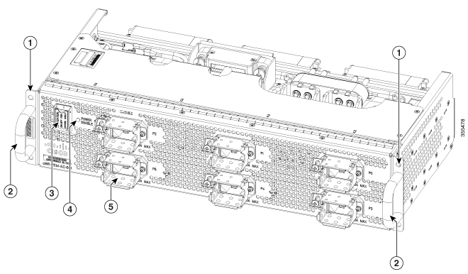
Power Cassette Module
The Power Cassette Module provides the physical support and keying for the Power Modules. It is keyed with a corresponding FPEM to determine AC or DC support.
This module is installed in the front of the Cisco cBR chassis.

|
1 |
Mounting flange |
2 |
AC Power Module bay |
|
1 |
Mounting flange |
2 |
DC Power Module bay |
|
Unit |
Value |
|---|---|
|
AC Power Cassette Module |
|
|
Depth |
16.9 in (42.92 cm) |
|
Width |
17.3 in (43.94 cm) |
|
Height |
3.7 in (9.4 cm) |
|
Maximum weight |
17 lb (7.7 kg) |
|
DC Power Cassette Module |
|
|
Depth |
16.9 in (42.92 cm) |
|
Width |
17.3 in (43.94 cm) |
|
Height |
3.7 in (9.4 cm) |
|
Maximum weight |
17 lb (7.7 kg) |
The Power Cassette Module supports six Power Modules. The front Power Module slots are numbered from P0 to P5 on the Power Cassette Module and these designations map to the facility power outlet markings on the rear of the chassis.
FPEM
The FPEM provides the following:
-
Physical interface and interconnection to the Power Modules for either AC or DC input voltage.
-
Digital communication from the Power Modules to the digital midplane.
-
Power interconnection from the Power Modules to the midplane bus bar.
The FPEM is installed in the rear of the Cisco cBR chassis. It is field replaceable to allow the facility to change from AC to DC power, or vice versa, without replacing the chassis.
Note |
Starting from April, 2018, Cisco ships the cBR8 router with AC FPEM VER 02 with no AC PRESENT LEDs as shown in the figure. VER 01 of AC FPEM has P0 AC PRESENT through P5 AC PRESENT that indicates input AC power for the corresponding AC Power Module (also indicated on the front-side of the Power Module). |
|
1 |
Mounting flange |
4 |
Power Enable LED |
|
2 |
Handle |
5 |
AC power input connector |
|
3 |
Power switch |

|
1 |
Mounting flange |
6 |
Negative lead |
|
2 |
Handle |
7 |
Positive lead |
|
3 |
Power switch |
8 |
Power Enable LED |
|
4 |
Terminal block cover |
9 |
DC Present LED |
|
5 |
Terminal bolt |
— |
|
Unit |
Value |
|---|---|
|
AC FPEM |
|
|
Depth |
10.08 in (25.6 cm) |
|
Width |
17.45 in (44.32 cm) |
|
Height |
3.85 in (9.78 cm) |
|
Maximum weight |
15 lb (6.8 kg) |
|
DC FPEM |
|
|
Depth |
10.08 in (25.6 cm) |
|
Width |
17.45 in (44.32 cm) |
|
Height |
3.85 in (9.78 cm) |
|
Maximum weight |
15 lb (6.8 kg) |
Both AC and DC FPEMs have a power switch to enable power to the entire Cisco cBR chassis.
The AC FPEM has the following LED:
-
POWER ENABLE—Power status LED
The DC FPEM has the following LEDs:
-
POWER ENABLE—Power status LED
-
DC PRESENT—Input DC power status LED for each terminal block
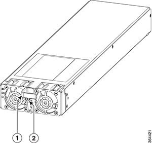
Power Module
The Power Modules provide the power conversion, filtering, and conditioning from facility input power to the required -52 V midplane power that is used within the chassis. Both AC and DC Power Modules are available depending on the facility input voltage. These modules have internal fans for cooling.
The Power Modules are installed in the front of the Cisco cBR chassis.
|
1 |
Handle |
2 |
Screw |

|
1 |
Handle |
2 |
Screw |
|
Unit |
Value |
|---|---|
|
AC Power Module |
|
|
Depth |
16.94 in (43.02 cm) |
|
Width |
4 in (10.16 cm) |
|
Height |
1.6 in (4.06 cm) |
|
Maximum weight |
6 lb (2.72 kg) |
|
DC Power Module |
|
|
Depth |
16.94 in (43.02 cm) |
|
Width |
4 in (10.16 cm) |
|
Height |
1.6 in (4.06 cm) |
|
Maximum weight |
6 lb (2.72 kg) |
Both AC and DC Power Modules have the following LEDs:
-
Input power LED—Power input status LED
-
Output power LED—Power output status LED
-
Fault LED—Fault status LED
Fan Module
The Cisco cBR-8 router has multiple modular Fan Modules installed in the rear to supply cooling air and have five Fan Module bays in the rear of the chassis. The bays are numbered from P10 to P14.
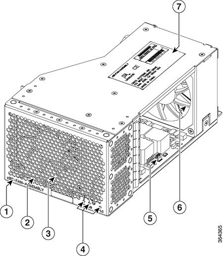
|
1 |
Product Identifier (PID) |
5 |
Control Panel |
|
2 |
Front Grille Panel |
6 |
Rear Fan |
|
3 |
Front Fan |
7 |
PID label |
|
4 |
LEDs |
— |
Each Fan Module has two fans and a control board. The fans in each Fan Module are synchronized and operate at variable speeds as set by the Supervisor. Fan speeds are determined based on ambient temperature and pressure. When the chassis boots up, the operating speed of the fans is set to the default number of revolutions per minute (RPM) in unsupervised mode. The multi Fan Module cooling architecture permits only one fan failure at any time in any given Fan Module during normal operational conditions. All the remaining fans are capable of changing to full speed operation to compensate for the failed fan or module.
Each fan bay has one hinged rear door and one sliding side door which close when a Fan Module is removed for replacement. This prevents re-circulation of air which could lead to the system overheating. The multi cooling architecture permits only one fan failure at any time in any given during normal operational conditions. All the remaining fans are capable of changing to full speed operation to compensate for the failed fan or module.
 Warning |
Ensure that all Fan Module bays have functioning Fan Modules. If a Fan Module is removed, replace it with a functioning Fan Module within one minute of the removal in order to avoid critical thermal alarms relating to overheating of individual components. |
|
Unit |
Value |
|---|---|
|
Depth |
8.40 in (21.34 cm) |
|
Width |
5.20 in (13.20 cm) |
|
Height |
3.50 in (8.89 cm) |
|
Weight |
4 lbs (1.81 kg) |
The faceplate of the Fan Module has the following LEDs:
|
LED |
Description |
|---|---|
|
STATUS 1 |
Status of the rear fan that faces inside the chassis. |
|
STATUS 2 |
Status of the front fan that faces outside the chassis. |
|
RPLC |
Failure and replacement status of the Fan Module. |
Cooling System of the Cisco cBR Chassis
The Fan Modules in the Cisco cBR chassis are controlled by the Supervisor Card. Until the Supervisor Card boots up, the fans spin at default speed of 11000 RPM. After Supervisor Card boot-up, the Supervisor Card controls the fan speeds, based on the temperature of the air entering the chassis and the barometric pressure reported by the sensors in the Fan Modules.
Failure Responses and Fan Speed Variations
The fan module will change speed based on the following conditions:
- When communication with the Supervisor Card is lost, both the fans in the Fan Module are set the 11,000 RPM default speed mode until communication is established. If the fans were running above 11,000 RPM default when communication was lost, the fans continue to operate at the elevated speeds until they are power cycled.
- If a fan is considered to
have failed if it operates at +/- 1000rpm from the set point. All fans are
elevated in speed based on facility air inlet temperature to the
Supervisor Card as safety
measure, by a temperature sensor on the
Supervisor Card. The front
panel LED of the
Fan Module indicates an
amber color LED. If there is an indication of a fan failure the
Supervisor Card sets all the
fan modules to a higher RPM value based on the inlet temperature on the
Supervisor Card. The
Supervisor Card sets the
following values:
-
13,000RPM (194CFM) for T≤30C
-
14,500RPM (218 CFM) for 30<T≤ 40C
-
16,000RPM (239 CFM) for T>40C
-
- A fan operating at speeds between 301 and 999 RPM from the set point, is considered a minor fan alarm. The fan speeds are not elevated in case of a minor alarm. The Fan Module amber LED is illuminated.
- When the chassis is booted and a fan is missing or removed the Supervisor Card sets all the other operational fans to 16,000 RPM. The chassis will not boot with a missing Fan Module. When a working Fan Module is replaced and all the other Fan Modules are working correctly the Supervisor Card will return all the fans to their normal operational speed. When a Fan Module is initially removed the Supervisor Card sets all the remaining fans to run at 13,000 RPM for 10 seconds, 14,500 RPM for 30 seconds, ramping to 15,000RPM for the next 30 seconds and then ramping to 16,000RPM until all the Fan Modules are again shown present.
Note |
Variations in speeds occur to regulate the internal component temperatures. Such speed variations are normal, in the absence of any alarms. For more details, see Monitoring the Fan Modules. |
Air Filter
The air filter is a field replaceable unit on the Supervisor and RF line cards. It removes dust in the air that is drawn into the router by the cooling fans. We recommend that you examine the air filter at least once a month or more often if required. Do not clean and re-use air filters. They must be replaced when they are clogged or worn out.
Note |
You can remove and install an air filter when the Cisco cBR router is powered on and working. |
Cisco IOS-XE Software
The Cisco cBR Series Converged Broadband Router (Cisco cBR) runs the Cisco IOS-XE software, which is stored on the Type II PCMCIA flash memory disks stored in the two PCMCIA slots in the primary route processor module. A PCMCIA flash memory disk in either slot can store a Cisco software image or configuration file. In addition to the flash memory disks, each route processor module contains onboard flash memory that is used to store a boot loader. The loader executes following a system reset to reload and execute the Cisco IOS-XE software on the flash memory disks.
The route processor module also stores the system configuration in the onboard flash memory. The configuration information read from the flash memory is buffered in operational memory following initialization, and is written to the flash memory device when the configuration is saved. Each line card also contains onboard flash memory that is used to store a boot loader, similar in function to that used on the route processor module. However, the line card loader executes following a system reset, line card reset, or line card insertion to reload and execute any code that must run on the line card. Software images may also be stored on an external TFTP server. If the Cisco cBR is so configured, it then downloads the proper image from the TFTP server and executes it.
NEBS Level 3 Compliance
The Cisco cBR is designed to meet Network Equipment Building System (NEBS) Level 3 compliance.
 Feedback