-
- Downstream Interface Configuration
- Upstream Interface Configuration
- DOCSIS Interface and Fiber Node Configuration
- DOCSIS Load Balancing Groups
- DOCSIS Load Balancing Movements
- DOCSIS 3.0 Downstream Bonding
- DOCSIS 2.0 A-TDMA Modulation Profiles
- Downstream Resiliency Bonding Group
- Downstream Channel ID Assignment
- Upstream Channel Bonding
- Spectrum Management and Advanced Spectrum Management
- Upstream Scheduler Mode
- Generic Routing Encapsulation
- Transparent LAN Service over Cable
- Downgrading Channel Bonding in Battery Backup Mode
- Energy Management Mode
-
- IP Access Control Lists
- Creating an IP Access List and Applying It to an Interface
- Creating an IP Access List to Filter IP Options, TCP Flags, Noncontiguous Ports
- Refining an IP Access List
- IP Named Access Control Lists
- IPv4 ACL Chaining Support
- IPv6 ACL Chaining with a Common ACL
- Commented IP Access List Entries
- Standard IP Access List Logging
- IP Access List Entry Sequence Numbering
- ACL IP Options Selective Drop
- ACL Syslog Correlation
- IPv6 Access Control Lists
- IPv6 Template ACL
- IPv6 ACL Extensions for Hop by Hop Filtering
-
- Call Home
- SNMP Support over VPNs—Context-Based Access Control
- SNMP Cache Engine Enhancement
- Onboard Failure Logging
- Control Point Discovery
- IPDR Streaming Protocol
- Usage-Based Billing (SAMIS)
- Frequency Allocation Information for the Cisco CMTS Routers
- Flap List Troubleshooting
- Maximum CPE and Host Parameters
- SNMP Background Synchronization
- Online Offline Diagnostics
- Index
Cisco Converged Broadband Routers Software Configuration Guide for DOCSIS 3.0
Bias-Free Language
The documentation set for this product strives to use bias-free language. For the purposes of this documentation set, bias-free is defined as language that does not imply discrimination based on age, disability, gender, racial identity, ethnic identity, sexual orientation, socioeconomic status, and intersectionality. Exceptions may be present in the documentation due to language that is hardcoded in the user interfaces of the product software, language used based on RFP documentation, or language that is used by a referenced third-party product. Learn more about how Cisco is using Inclusive Language.
- Updated:
- April 12, 2015
Chapter: Cisco Network Registrar for the Cisco CMTS Routers
- Hardware Compatibility Matrix for Cisco cBR Series Routers
- Servers Required on the HFC Network
- Cisco Network Registrar Description
- Overview of DHCP Using CNR
- How Cisco Converged Broadband Routers and Cable Modems Work
- DHCP Fields and Options for Cable Modems
- Cisco Network Registrar Sample Configuration
- Overview of Scripts
- Placement of Scripts
- Activating Scripts in Cisco Network Registrar
- Configuring the Cisco CMTS Routers to Use Scripts
- Configuring the System Default Policy
- Creating Selection Tag Scopes
- Creating Network Scopes
- Creating Policies for Class of Service or for Upgrading Cable Modem Cisco IOS Images
- CNR Steps to Support Subinterfaces
- Additional References
Cisco Network Registrar for the Cisco CMTS Routers
This chapter supplements the Cisco Network Registrar (CNR) documentation by providing additional cable-specific instructions to provision a hybrid fiber-coaxial (HFC) network using Cisco universal broadband routers as CMTSs at the headend of the network.
 Note | For information about the IPv6 provisioning on CNR server, please refer to IPv6 on Cable. |
Finding Feature Information
Your software release may not support all the features documented in this module. For the latest feature information and caveats, see the release notes for your platform and software release. To find information about the features documented in this module, and to see a list of the releases in which each feature is supported, see the Feature Information Table at the end of this document.
Use Cisco Feature Navigator to find information about platform support and Cisco software image support. To access Cisco Feature Navigator, go to http://tools.cisco.com/ITDIT/CFN/. An account on http://www.cisco.com/ is not required.
Contents
- Hardware Compatibility Matrix for Cisco cBR Series Routers
- Servers Required on the HFC Network
- Cisco Network Registrar Description
- Overview of DHCP Using CNR
- How Cisco Converged Broadband Routers and Cable Modems Work
- DHCP Fields and Options for Cable Modems
- Cisco Network Registrar Sample Configuration
- Overview of Scripts
- Placement of Scripts
- Activating Scripts in Cisco Network Registrar
- Configuring the Cisco CMTS Routers to Use Scripts
- Configuring the System Default Policy
- Creating Selection Tag Scopes
- Creating Network Scopes
- Creating Policies for Class of Service or for Upgrading Cable Modem Cisco IOS Images
- CNR Steps to Support Subinterfaces
- Additional References
Hardware Compatibility Matrix for Cisco cBR Series Routers
Note | The hardware components introduced in a given Cisco IOS-XE Release are supported in all subsequent releases unless otherwise specified. |
|
Cisco CMTS Platform |
Processor Engine |
Interface Cards |
|---|---|---|
|
Cisco cBR-8 Converged Broadband Router |
Cisco IOS-XE Release 3.15.0S and Later Releases Cisco cBR-8 Supervisor:
|
Cisco IOS-XE Release 3.15.0S and Later Releases Cisco cBR-8 CCAP Line Cards: Cisco cBR-8 Downstream PHY Modules: Cisco cBR-8 Upstream PHY Modules: |
Servers Required on the HFC Network
A TFTP server, DHCP server, and time-of-day (TOD) server are required to support two-way data cable modems on an HFC network. A cable modem will not boot if these servers are not available. The log server and security servers are not required to configure and operate a cable modem. If the log server or security servers are not present, a cable modem will generate warning messages, but it will continue to boot and function properly.
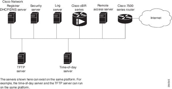
In this provisioning model, TOD and TFTP servers are standard Internet implementations of the RFC 868 and RFC 1350 specifications. Most computers running a UNIX-based operating system supply TOD and TFTP servers as a standard software feature. Typically, the TOD server is embedded in the UNIX inetd and it requires no additional configuration. The TFTP server is usually disabled in the standard software but can be enabled by the user. Microsoft NT server software includes a TFTP server that can be enabled with the services control panel. Microsoft NT does not include a TOD server. A public domain version of the TOD server for Microsoft NT can be downloaded from several sites.
The DHCP and Domain Name System (DNS) server shown in Figure above must be the DHCP/DNS server available in Cisco Network Registrar version 2.0 or later. CNR is the only DHCP server that implements policy-based assignment of IP addresses. The headend must be a Cisco cBR-8 converged broadband router. The remote access server is only required on HFC networks that are limited to one-way (downstream only) communication. In a one-way HFC network, upstream data from a PC through the headend to the Internet is carried over a dialup connection. This dialup connection for upstream data is referred to as telco return. For simplification, the model will not include a log or security server. Cable modems can be set up to use the logging and security servers by including the appropriate DHCP options in the cable modem policy as described in the Cisco Network Registrar User Manual.
Cisco Network Registrar Description
CNR is a dynamic IP address management system, running on Windows or Solaris, that uses the Dynamic Host Configuration Protocol (DHCP) to assign IP addresses to cable interfaces, PCs, and other devices on the broadband network. The CNR tool includes script extensions that allow a cable system administrator to define and view individual DHCP options, define the identity or type of device on the network, and assign the device to a predefined class or group.
Using the CNR tool, a cable system administrator can specify policies to provide:
- Integrated DHCP and Domain Name Server (DNS) services
- Time of Day (ToD) and Trivial File Transfer Protocol (TFTP) server based on the size of the network
- DHCP safe failover and dynamic DNS updates
Note | This is available only in CNR 3.0 or higher. |
Using the CNR tool and the extension scripts identified in the Overview of Scripts section, a cable system administrator can specify scopes, policies, and options for the network and each cable interface based on the services and configuration to support at each subscriber site.
Note | Scopes refer to the administrative grouping of TCP/IP addresses; all IP addresses within a scope should be on the same subnet. |
The cable system administrator defines system default policies for all standard options and uses scope-specific policies for options related to particular subnets, such as cable interfaces. This allows DHCP to send the information with the IP address.
Seven entry points exist for scripts:
- post-packet-decode
- pre-client-lookup
- post-client-lookup—Examines and takes action on results of the client-class process, places data items in the environment dictionary to use at the pre-packet-encode extension point, includes DHCP relay option
- check-lease-acceptable
- pre-packet-encode
- post-sent-packet
- pre-dns-add-forward
Overview of DHCP Using CNR
Cisco Network Registrar (CNR) is a dynamic IP address management system that uses the Dynamic Host Configuration Protocol (DHCP) and assigns IP addresses to PCs and other devices on a network based on a predefined set of policies, such as class of service. CNR assigns available IP addresses from address pools based on the identity or type of the requesting device and the policies in effect. For example, CNR can distinguish between registered devices, unregistered devices, and registered devices that have been assigned to a particular class of service.
CNR also provides extensions that can be customized (via programming or a script) so that you can view individual DHCP options, determine the identity or type of a device based on the content of the options, and assign a device to a predefined class or group. Using these extensions, you can determine the difference between PCs and cable modems and assign them IP addresses from different address pools.
In typical data-over-cable environments, service providers are interested in simplifying provisioning to limit the amount of information that must be collected about subscribers’ customer premise equipment (CPEs). To support current provisioning models, a field technician must be sent to a subscriber’s home or business to install and setup a cable modem. During this site visit, the technician might register the serial number and MAC address of the cable modem in the customer account database. Because a field technician must go to a subscriber’s site to replace a cable modem, you can easily track modem information.
Manually registering and tracking information about a cable subscriber’s PC is more difficult. A subscriber might purchase a new PC or exchange the network interface card (NIC) without notifying you of the change. Automatic provisioning with CNR reduces the amount of customer service involvement needed to track customer equipment. To use the provisioning model described in this document, you must still track serial numbers and MAC addresses for cable modems, but you do not need to track information about the PC or NIC cards installed at a subscriber site.
The remainder of this document describes how to configure CNR to support this model. The following sections describe the equipment and servers required for the cable headend, provide an overview of the interaction between DOCSIS-compatible cable modems and the Cisco universal broadband routers, and provide a guide on how to configure CNR to support this provisioning model.
How Cisco Converged Broadband Routers and Cable Modems Work
Cisco converged broadband routers and cable modems are based on the Data Over Cable Service Interface Specification (DOCSIS) standards. These standards were created by a consortium of cable service providers called Multimedia Cable Network Systems, Ltd. (MCNS) to that cable headend and cable modem equipment produced by different vendors will interoperate. The key DOCSIS standards provide the basis for a cable modem to communicate with any headend equipment and headend equipment to communicate with any cable modem.
Cable modems are assigned to operate on specific cable channels so activity can be balanced across several channels. Each Cisco cBR-8 router installed at the headend serves a specific channel. Part of network planning is to decide which channel each cable modem can use.
A cable modem cannot connect to the network until the following events occur:
- The cable modem initializes and ranges through available frequencies until it finds the first frequency that it can use to communicate to the headend. The cable modem might be another vendor’s DOCSIS-compatible device and the headend might have a Cisco cBR-8 router installed. At this point on the initial connection, the cable modem cannot determine if it is communicating on the correct channel.
- The cable modem goes through the DHCP server process and receives a configuration file from the server.
- One of the parameters in the configuration file tells the cable modem which channel it can use.
- If the assigned channel is not available on the Cisco cBR-8 router to which the cable modem is currently connected, it resets itself and comes up on the assigned channel.
- During this second DHCP process, the modem will be connected to the correct CMTS. This time, the configuration file will be loaded. For a DOCSIS-compatible cable modem to access the network, it might go through the DHCP server two times on two different networks; therefore, one-lease-per-client IP addressing is critical.
DHCP Fields and Options for Cable Modems
DHCP options and packet fields are required to enable cable modems to boot and operate properly. Table below lists the required DHCP options and fields.
|
Required Field/Option |
Field/Option In Cisco Network Registrar |
Value/Description |
|---|---|---|
|
Fields |
||
|
giaddr |
- |
IP address. As a DHCP packet passes through the relay agent to the DHCP server, the relay agent supplies a unique IP address to the packet and stores it in this field. The relay agent is a cBR-8 router with the iphelper attribute defined. |
|
subnet-mask |
- |
Subnet mask for the IP address stored in the giaddr field. This value is also stored in the DHCP packet by the relay agent. |
|
file |
Packet-file-name |
Name of the cable modem configuration file that will be read from a TFTP server. |
|
siaddr |
Packet-siaddr |
IP address of the TFTP server where configuration files are stored. |
|
Options |
||
|
Time-servers |
- |
List of hosts running the time server specified in the RFC 868 standard. |
|
Time-offset |
- |
Time offset of a cable modem internal clock from Universal Time Coordinated (UTC). This value is used by cable modems to calculate the local time that is stored in time-stamping error logs. |
|
MCNS-security-server |
- |
IP address of the security server. This should be set if security is required. See RFC 1533 for details. |
Cisco Network Registrar Sample Configuration
You can use the following information to set up Cisco Network Registrar in a trial configuration. The configuration describes DHCP-related setup only; it does not cover setting up DNS or configuring dynamic DNS (DDNS). You should be familiar with important CNR concepts including scopes, primary and secondary scopes, scope selection tags, client classes, and CNR policies. See the Using Network Registrar publication for detailed information on these concepts.
In the trial configuration, you can configure CNR to perform the following operations:
- Receive DHCP requests from a cable modem and a PC on an HFC network via a port supporting multiple network numbers. The Cisco cBR-8 router at the headend must be configured as a forwarder (iphelper is configured).
- Serve IP addresses on two networks; a net-10 network (non-Internet routable) and a net-24 network (Internet routable).
- Tell the difference between a cable modem and a PC based on the MAC address of the device and provide net-24 addresses to the PC and net-10 addresses to the cable modem.
- Refuse to serve IP addresses to MAC addresses that it does not recognize.
To perform these options, you must implement the following CNR configuration items:
- Create two scope selection tags; one for PCs, one for cable modems.
- Create two client-classes; one for PCs , one for cable modems.
- Create a lease policy appropriate for the cable modem devices.
- Create a lease policy appropriate for the PC devices.
- Create a scope containing Class A net-24 (routable) addresses.
- Create a scope containing Class A net-10 (nonroutable) addresses.
- Identify the scope containing the net-24 addresses as the primary scope and configure the other scope containing the net-10 addresses as secondary to the net-24 scope.
Note | The Cisco cBR-8 router upstream ports must be configured with the primary network address on the net-24 network; such as 24.1.1.1. |
- Assign the policies to the appropriate scope.
- Add the MAC address of the cable modem and the PC to the client-entry list.
- Associate the PC tag with the scope containing routable addresses.
- Associate the cable modem tag with the scope containing nonroutable addresses.
- Associate the cable modem tag with the cable modem client-class.
- Associate the PC tag with the PC client-class.
- Assign the PC MAC to the PC class.
- Assign the cable modem MAC to the cable modem class.
- Enable client-class processing.
Figure below shows the trial CNR configuration in an HFC network.
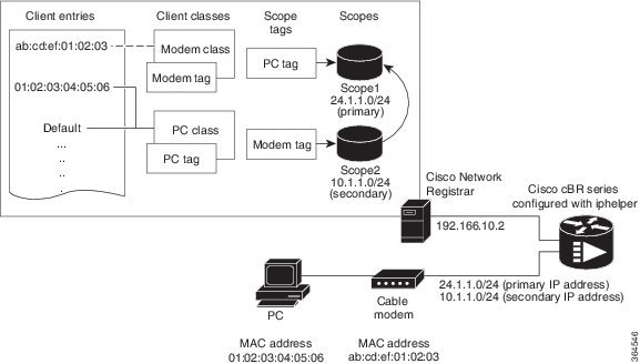
These configuration items and their associations can be created using either the CNR management graphical user interface (GUI) or command-line interface (CLI). The following sample script configures DHCP for a sample server:
File: cabledemo.rc
Command line: nrcmd -C <cluster> -N <user name> -P <password> -b < cabledemo.rc
---------------------------------------------------------------------------------------
scope-selection-tag tag-CM create
scope-selection-tag tag-PC create
client-class create class-CM
client-class class-CM set selection-criteria=tag-CM
client-class create class-PC
client-class class-PC set selection-criteria=tag-PC
policy cmts-cisco create
policy cmts-cisco setleasetime 1800
policy cmts-cisco setoption domain-name-servers 192.168.10.2
policy cmts-cisco setoption routers 10.1.1.1
policy cmts-cisco setoption time-offset  604800
policy cmts-cisco setoption time-servers 192.168.10.20
policy cmts-cisco set packet-siaddr=192.168.10.2
policy cmts-cisco setoption log-servers 192.168.10.2
policy cmts-cisco setoption mcns-security-server 192.168.10.2
policy cmts-cisco set packet-file-name=golden.cfg
policy cmts-cisco set dhcp-reply-options=packet-file-name,packet-siaddr,mcns-security-server
policy pPC create
policy pPC set server-lease-time 1800
policy pPC setleasetime 1800
policy pPC setoption domain-name-servers 192.168.10.2
policy pPC setoption routers 24.1.1.1
scope S24.1.1.0 create 24.1.1.0 255.255.255.0
scope S24.1.1.0 addrange 24.1.1.5 24.1.1.254
scope S24.1.1.0 set policy=pPC
scope S24.1.1.0 set selection-tags=tag-PC
scope S10.1.1.0 create 10.1.1.0 255.255.255.0
scope S10.1.1.0 addrange 10.1.1.5 10.1.1.254
scope S10.1.1.0 set policy=cmts-cisco
scope S10.1.1.0 set selection-tags=tag-CM
scope S10.1.1.0 set primary-scope=S24.1.1.0
client 01:02:03:04:05:06 create client-class-name=class-PC
client ab:cd:ef:01:02:03 create client-class-name=class-CM
client default create action=exclude
dhcp enable client-class
dhcp enable one-lease-per-client
save
dhcp reload
In addition to the DHCP server setup, you might want to enable packet-tracing. When packet-tracing is enabled, the server parses both requests and replies, and then adds them to the logs. If you do enable tracing, performance will be adversely affected, and the logs will roll over quickly.
Use the following nrcmd command to set packet tracing.
DHCP set log-settings=incoming-packet-detail,outgoing-packet-detail
Cable Modem DHCP Response Fields
Each cable interface on the broadband network requires the following fields in the DHCP response:
Note | For cable operators with less experience in networking, you can fill in a guess based on the network number and indicate how your IP network is divided. |
- Name of the DOCSIS configuration file on the TFTP server intended for the cable interface
- Time offset of the cable interface from the Universal Coordinated Time (UTC), which the cable interface uses to calculate the local time when time-stamping error logs
- Time server address from which the cable interface obtains the current time
DOCSIS DHCP Fields
DOCSIS DHCP option requirements include:
- IP address of the next server to use in the TFTP bootstrap process; this is returned in the siaddr field
- DOCSIS configuration file that the cable interface downloads from the TFTP server
Note | If the DHCP server is on a different network that uses a relay agent, then the relay agent must set the gateway address field of the DHCP response. |
DHCP Relay Option (DOCSIS Option 82)
DOCSIS Option82 modifies DHCPDISCOVER packets to distinguish cable interfaces from the CPE devices or “clients” behind them. The DOCSIS Option82 is comprised of the following two suboptions:
Type 1 (1 byte)
Len 4 (1 byte)
Value (8 bytes)
<bit 31,30,....................0)
<xYYYYYYYYYYYYYYYYYYYYYYYYYYYYYY>
where the MSB indicates if the attached device is a cable interface.
x=1 Cable Modem REQ
x=0 CPE device (Behind the cable interface with the cable interface MAC address shown in suboption 2.)
The rest of the bits make up the SNMP index to the CMTS interface.
Y=0xYYYYYYY is the SNMP index to the CMTS interface.
Type 2 (1 byte)
Len 6 (1 byte)
Value xxxx.xxxx.xxxx (6 bytes)
Overview of Scripts
This section lists the scripts applicable to cable interface configuration.
Two-way Cable Modem Scripts
To support two-way configurations at a subscriber site, use these scripts:
Telco Return Cable Modem Scripts
To support telco return and two-way cable interface configurations on the same cable interface card or chassis, use these scripts:
Placement of Scripts
Windows NT
For CNR running on Windows NT, place the appropriate scripts in the following directory:
\program files\network registrar\extensions\dhcp\scripts\tcl
Solaris
For CNR running on Solaris, place the appropriate scripts in the following directory:
/opt/nwreg2/extensions/dhcp/scripts/tcl
Activating Scripts in Cisco Network Registrar
To activate the scripts after you have placed them in the appropriate directory:
Configuring the Cisco CMTS Routers to Use Scripts
Each cable interface must be set up as a BOOTP forwarder and have the relay option enabled. The primary and secondary IP addresses for each cable interface must be in sync with the CNR tool.
To properly communicate with scripts in the system, use the following commands on the Cisco CMTS router:
- To enable option 82, use the ip dhcp relay info option command.
- To disable the validation of DHPC relay agent information in forwarded BOOTREPLY messages, use the no ip dhcp relay information option check command.
Note | You can also use the cable dhcp-giaddr command in cable interface configuration mode to modify the GIADDR field of DHCPDISCOVER and DHCPREQUEST packets to provide a relay IP address before packets are forwarded to the DHCP server. Use this command to set a “policy” option such that primary addresses are used for CMs and secondary addresses are used for hosts behind the CMs. |
Configuring the System Default Policy
Add these options to the system default policy for:
Cable Modems
Define these settings following the CNR tool documentation:
- TFTP server (IP address) for those cable interfaces using BOOTP
- Time-server (IP address)
- Time-offset (Hex value, 1440 for Eastern Standard Time)
- Packet-siaddr (IP address of CNR)
- Router (set to 0.0.0.0)
- Boot-file (name of .cm file for those cable interfaces using BOOTP)
- Packet-file-name (.cm file name)
PCs
Define these settings following the CNR tool documentation:
- Domain name
- Name servers (IP address of DNS servers)
Creating Selection Tag Scopes
General
When you create your scope selection tags:
Telco Return for the Cisco cBR-8 Router
Note | If you are using the prepacketencode and postclientlookup .tcl scripts for telco return, the telco return scope does not have a selection tag associated to the scope. |
Creating Network Scopes
Following is an example for creating scopes for your network. This example assumes two Cisco cBR-8 converged broadband routers in two locations, with one cable interface card on one Cisco cBR-8 configured for telco return.
cm-toledo1_2-0 10.2.0.0 255.255.0.0 assignable 10.2.0.10-10.2.254.254 tagCablemodem tagTelcomodem Default GW=10.2.0.1 (assigned by scripts)
cm-toledo1_3-0 10.3.0.0 255.255.0.0 assignable 10.3.0.10-10.3.254.254 tagCablemodem tagTelcomodem Default GW=10.3.0.1 (assigned by scripts)
pc-toledo1_2-0 208.16.182.0 255.255.255.248 assignable 208.16.182.2-208.16.182.6 tagComputer Default GW=208.16.182.1 (assigned by scripts)
pc-toledo1_3-0 208.16.182.8 255.255.255.248 assignable 208.16.182.10-208.16.182.14 tagComputer Default GW=208.16.182.9 (assigned by scripts)
telco_return_2-0 192.168.1.0 255.255.255.0 (No assignable addresses, tag was put on cable modem primary scope to force telco-return cable modem to pull address from primary scope)
cm-arlington1_2-0 10.4.0.0 255.255.0.0 assignable 10.4.0.10-10.4.254.254 tagCablemodem Default GW=10.4.0.1 (assigned by scripts)
cm-arlington1_3-0 10.5.0.0 255.255.0.0 assignable 10.5.0.10-10.5.254.254 tagCablemodem Default GW=10.5.0.1 (assigned by scripts)
pc-arlington1_2-0 208.16.182.16 255.255.255.248 assignable 208.16.182.17-208.16.182.22 tagComputer Default GW=208.16.182.17 (assigned by scripts)
pc-toledo1_3-0 208.16.182.24 255.255.255.248 assignable 208.16.182.2-208.16.182.30 tagComputer Default GW=208.16.182.25 (assigned by scripts)
Note | Remember the last valid address in the .248 subnet range is the broadcast address; do not use this. |
Creating Policies for Class of Service or for Upgrading Cable Modem Cisco IOS Images
To support Class of Service (CoS), define:
Note | This is needed for Option82. |
Note | Scope selection tags are excluded from or included in client-classes. |
To assign the CoS or use Option82, make a client entry with a MAC address and point to the appropriate policy. To use client-based MAC provisioning, add a client entry “default - exclude,” then put in MAC addresses for all devices (for example, cable interfaces and PCs) in the client tab and select the policy to use, including the appropriate tag.
CNR Steps to Support Subinterfaces
The CNR configuration is done differently if subinterfaces are configured. Here is an example. If you have configured two ISP subinterfaces and one management subinterface on a Cisco cBR-8 router, make sure that the management subinterface is the first subinterface that is configured. If cable interface three—c3/0/0—is being used, create c3/0/0.1, c3/0/0.2 and c3/0/0.3 as three subinterfaces and c3/0/0.1 as the first subinterface configured as the management subinterface.
Note | The Cisco cBR-8 router requires management subinterfaces to route DHCP packets from CMs when they first initialize because the Cisco cBR-8 router does not know the subinterfaces they belong to until it has seen the IP addresses assigned to them by gleaning DHCP reply message from CNR. |
In CNR, complete the following steps for such a configuration:
| Step 1 | Create two scope selection tags such as: isp1-cm-tag and isp2-cm-tag |
| Step 2 | Configure three scopes; for example, mgmt-scope, isp1-cm-scope, and isp2-cm-scope such that isp1-cm-scope and isp2-cm-scope each define mgmt-scope to be the primary scope |
| Step 3 | Also configure two scopes for PCs for each of the ISPs; isp1-pc-scope and isp2-pc-scope. For scope isp1-cm-scope, configure isp1-cm-tag to be the scope selection tag. For scope isp2-cm-scope, configure isp2-cm-tag to be the scope selection tag |
| Step 4 | Configure two client classes; for example, isp1-client-class and isp2-client-class |
| Step 5 | Create client entries with their MAC addresses for CMs that belong to ISP1 and assign them to isp1-client-class. Also assign the scope selection tag isp1-cm-tag |
| Step 6 | Create client entries for CMs that belong to ISP2 and assign them to isp2-client-class. Also assign the scope selection tag isp2-cm-tag |
| Step 7 | Enable client
class processing from the scope-selection-tag window
Overlapping address ranges cannot be configured on these subinterfaces because software gleans the DHCP reply to figure out the subinterface it really belongs to. Although CNR can be configured with overlapping address range scopes, it cannot be used to allocate addresses from these scopes. |
Additional References
The following sections provide references related to Cisco Network Registrar for use with the Cisco CMTS routers.
Technical Assistance
|
Description |
Link |
|---|---|
|
Technical Assistance Center (TAC) home page, containing 30,000 pages of searchable technical content, including links to products, technologies, solutions, technical tips, and tools. Registered Cisco.com users can log in from this page to access even more content. |
 Feedback