Cisco Wide Area Virtualization Engine 574 Hardware Installation Guide
Bias-Free Language
The documentation set for this product strives to use bias-free language. For the purposes of this documentation set, bias-free is defined as language that does not imply discrimination based on age, disability, gender, racial identity, ethnic identity, sexual orientation, socioeconomic status, and intersectionality. Exceptions may be present in the documentation due to language that is hardcoded in the user interfaces of the product software, language used based on RFP documentation, or language that is used by a referenced third-party product. Learn more about how Cisco is using Inclusive Language.
- Updated:
- July 2, 2009
Chapter: Introducing the Cisco Wide Area Virtualization Engine 574
Introducing the Cisco Wide Area Virtualization Engine 574
This chapter provides a basic functional overview of the Cisco Wide Area Virtualization Engine 574 (WAVE-574) appliance and describes the hardware, major components, and front and back panel indicators and controls.
This chapter contains the following sections:
•![]() System Board Components and LEDs
System Board Components and LEDs
Supported Products
The WAVE-574 appliance supports Cisco Wide Area Application Services (WAAS) software version 4.1.1 and later releases.
Hardware Features
This section illustrates and describes the front and back panel controls, ports, and LED indicators on the WAVE-574. It contains the following topics:
•![]() Front Panel Components and LEDs
Front Panel Components and LEDs
•![]() Back Panel Components and LEDs
Back Panel Components and LEDs
•![]() Location of Ports and Connectors
Location of Ports and Connectors
Front Panel Components and LEDs
Figure 1-1 shows the front panel components.
Figure 1-1 Front Panel
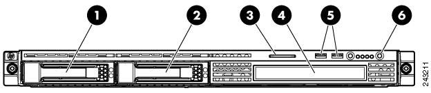
Figure 1-2 shows the front panel LEDs.
Figure 1-2 Front Panel LEDs
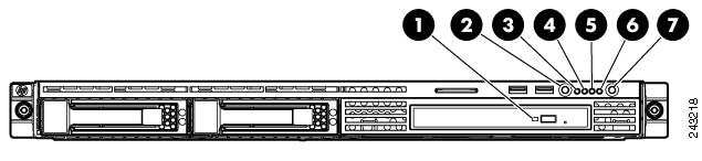
Table 1-1 describes the front panel LEDs and their functions.
|
|
|
|
|
|
|---|---|---|---|---|
|
|
DVD/CD-ROM drive activity LED |
Green |
On |
Drive activity is normal. |
Amber |
On |
Drive failure has occurred. |
||
— |
Off |
No drive activity exists. |
||
|
|
UID button/LED |
Blue |
On |
Identification is activated. |
Blue |
Flashing |
System is being remotely managed. |
||
— |
Off |
Identification is deactivated. |
||
|
|
Internal health LED |
Green |
On |
System health is normal. |
Amber |
On |
System health is degraded. A system board LED is lit inside the appliance. See the "System Board LEDs" section. |
||
Red |
On |
System health is critical. A system board LED is lit inside the appliance. See the "System Board LEDs" section. |
||
— |
Off |
System health is normal (when in standby mode). |
||
|
|
NIC 1 link/activity LED |
Green |
On |
Network link exists. |
Green |
Flashing |
Network link and activity exist. |
||
— |
Off |
No network link exists. If power is off, the front panel LED is not active. View the LEDs on the RJ-45 connector. |
||
|
|
NIC 2 link/activity LED |
Green |
On |
Network link exists. |
Green |
Flashing |
Network link and activity exist. |
||
— |
Off |
No network link exists. If power is off, the front panel LED is not active. View the LEDs on the RJ-45 connector. |
||
|
|
Drive activity LED |
Green |
On |
Drive activity is normal. |
Amber |
On |
Drive failure has occurred. |
||
— |
Off |
No drive activity exists. |
||
|
|
Power On/Standby button and system power LED |
Green |
On |
System is on. |
Amber |
On |
System is shut down, but power is still applied. |
||
— |
Off |
Power cord is not attached or power supply failure has occurred. |
Back Panel Components and LEDs
Figure 1-3 shows the back panel components.

Note ![]() You can connect a keyboard to any USB port and connect a monitor to the video connector to troubleshoot the BIOS boot process. However, video output is for troubleshooting only during the BIOS boot process. The video output stops displaying when the serial port becomes active. To monitor the boot process in normal operation, use the serial console port.
You can connect a keyboard to any USB port and connect a monitor to the video connector to troubleshoot the BIOS boot process. However, video output is for troubleshooting only during the BIOS boot process. The video output stops displaying when the serial port becomes active. To monitor the boot process in normal operation, use the serial console port.
Figure 1-3 Back Panel
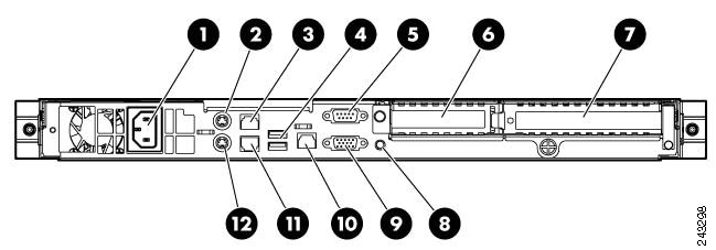
Figure 1-4 shows the back panel LEDs.
Figure 1-4 Back Panel LEDs
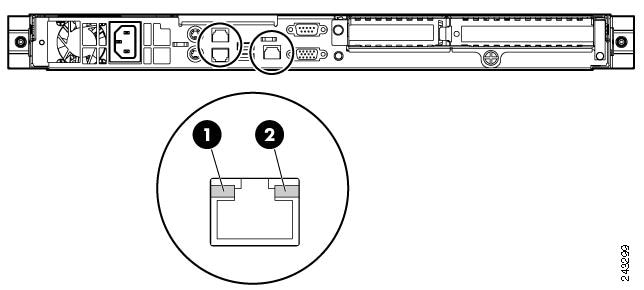
Table 1-2 describes the back panel LEDs and their functions.
|
|
|
|
|
|
|---|---|---|---|---|
|
|
NIC activity |
Green |
On |
Activity exists. |
Green |
Flashing |
|||
— |
Off |
No activity exists. |
||
|
|
NIC link |
Green |
On |
Link exists. |
— |
Off |
No link exists. |
Location of Ports and Connectors
The WAVE appliance supports two Ethernet connectors and one Console port on the back of the appliance.
Figure 1-3 shows the back panel ports and connectors.

Warning ![]() To avoid electric shock, do not connect safety extra-low voltage (SELV) circuits to telephone-network voltage (TNV) circuits. LAN ports contain SELV circuits, and WAN ports contain TNV circuits. Some LAN and WAN ports both use RJ-45 connectors. Use caution when connecting cables. Statement 1021
To avoid electric shock, do not connect safety extra-low voltage (SELV) circuits to telephone-network voltage (TNV) circuits. LAN ports contain SELV circuits, and WAN ports contain TNV circuits. Some LAN and WAN ports both use RJ-45 connectors. Use caution when connecting cables. Statement 1021
This section contains the following topics:
•![]() Console Port Serial Connector
Console Port Serial Connector
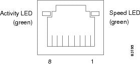
Ethernet Port Connectors
Connect a Category 3, 4, or 5 unshielded twisted-pair cable to an Ethernet connector. 100BASE-TX and 1000BASE-T Fast Ethernet standards require Category 5 or higher cabling.
The WAVE-574 appliance has two Ethernet connectors that are attached to the Ethernet controllers (see Figure 1-3 and Figure 1-5). The Ethernet controllers are integrated on the system board. They provide an interface for connecting to a 10-Mbps, 100-Mbps, or 1-Gbps network and provide full-duplex (FDX) capability, which enables simultaneous transmission and reception of data on the network. If the Ethernet ports in the server support auto negotiation, the controllers detect the data-transfer rate (10BASE-T, 100BASE-TX, or 1000BASE-T) and duplex mode (full duplex or half duplex) of the network and automatically operate at that rate and mode. You do not have to set any jumpers or configure the controllers.
Note ![]() There is a third RJ45 connector on the rear of the appliance (see Figure 1-3). This is the unused system management port. Do not connect this port to your network.
There is a third RJ45 connector on the rear of the appliance (see Figure 1-3). This is the unused system management port. Do not connect this port to your network.
If a problem occurs with the primary Ethernet connection, all Ethernet traffic associated with this primary connection is automatically switched to the redundant Ethernet connection. If the applicable device drivers are installed, switching occurs without data loss or user intervention.
Figure 1-5 Ethernet Port Connector
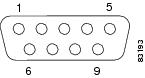
Console Port Serial Connector
The WAVE-574 appliance has one console port connector (see Figure 1-6). Use the console port connector to access the command-line interface (CLI) for controlling the WAVE appliance.
Figure 1-6 Console Port Serial Connector
System Board Components and LEDs
This section shows where the system board components are located, LED functions, and describes the system maintenance switch operating options.
This section contains the following topics:
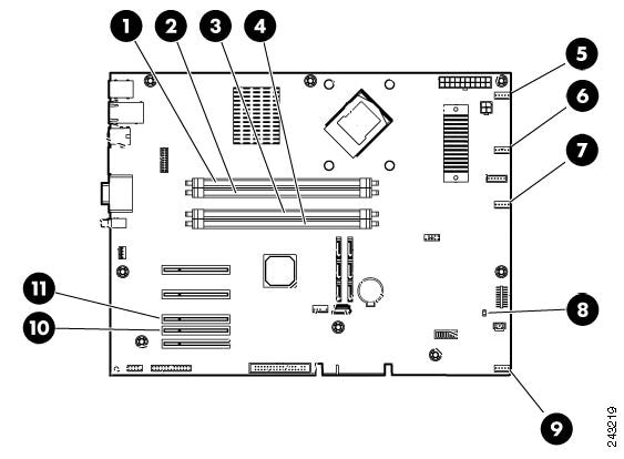
System Board Components
Figure 1-7 shows the layout of the system board components.
Figure 1-7 System Board Components
System Board LEDs
Figure 1-8 shows the system board LEDs.
Figure 1-8 System Board LEDs
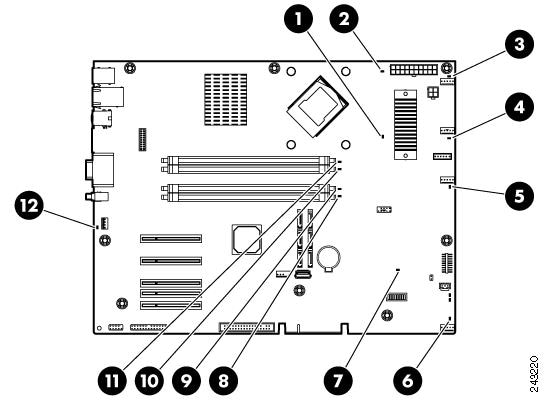
Table 1-3 describes the system board LED functions.
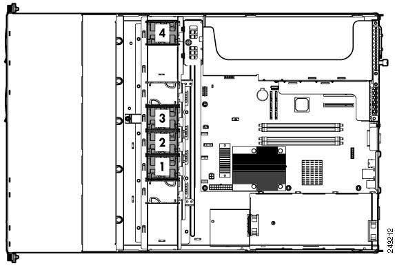
System Board Fans
Figure 1-9 shows the location of the system board fans that provide ventilation for the chassis.
Figure 1-9 System Board Fans
 Feedback