Cisco Wide Area Virtualization Engine 574 Hardware Installation Guide
Bias-Free Language
The documentation set for this product strives to use bias-free language. For the purposes of this documentation set, bias-free is defined as language that does not imply discrimination based on age, disability, gender, racial identity, ethnic identity, sexual orientation, socioeconomic status, and intersectionality. Exceptions may be present in the documentation due to language that is hardcoded in the user interfaces of the product software, language used based on RFP documentation, or language that is used by a referenced third-party product. Learn more about how Cisco is using Inclusive Language.
- Updated:
- October 15, 2008
Chapter: WAVE Inline Network Adapter
WAVE Inline Network Adapter
This chapter describes the Cisco WAVE inline network adapter and contains the following sections:
•![]() Inline Network Adapter Description
Inline Network Adapter Description
•![]() Inline Network Adapter Cabling Requirements
Inline Network Adapter Cabling Requirements
•![]() Installation Scenarios and Cabling Examples for Fast Ethernet Connections
Installation Scenarios and Cabling Examples for Fast Ethernet Connections
For information on installing an inline adapter in your WAVE-574, see the "Installing a Cisco WAVE Inline Adapter" section on page 4-3.
For adapter specifications, see Table A-2 in Appendix A.
Inline Network Adapter Description
The WAVE appliance supports one optional 2-port Gigabit Ethernet inline network adapter or one optional 4-port Gigabit Ethernet inline network adapter. The inline network adapter is a full-height, three-quarter-length PCI Express network interface card that contains two or four independent Gigabit Ethernet ports. (See Figure 5-1.)
Figure 5-1 4-Port Inline Network Adapter
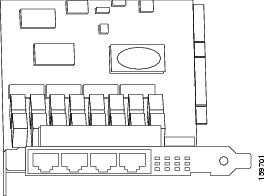
The Cisco WAVE inline network adapter provides an inline traffic interception capability for your appliance. When you configure the WAVE appliance for inline interception mode, you can set attributes to control which interfaces are to be used over which VLANs. By default, the adapter operates on all inline-capable interfaces and VLANs. You can configure the inline redirection feature using the WAAS CLI or the WAAS Central Manager GUI.

Note ![]() Throughout this section, we refer to a WAVE appliance configured for inline interception mode as a WAVE inline appliance.
Throughout this section, we refer to a WAVE appliance configured for inline interception mode as a WAVE inline appliance.
The WAAS software defines two new interface types: A group interface that represents an inline pair grouping and a port interface that represents the individual port. These interfaces are referred to as inlineGroup and inlinePort.
InlineGroup interfaces are numbered using the format slot/group. The slot number is the slot in which the adapter is inserted. The group number is either 0 or 1 (each adapter has 2 group pairs). The group number is displayed on the adapter label.
InlinePort interfaces are numbered slot/group/lan or slot/group/wan. The last attribute is the LAN or WAN designator.
The inline network adapter also includes an onboard programmable watch dog timer (WDT) controller that allows you to set the time to wait after a failure event, such as a power outage or a kernel crash, before the unit begins to operate in mechanical bypass mode. In mechanical bypass mode, the traffic is bridged between the LAN and WAN ports of each group. Mechanical bypass mode prevents the WAVE appliance from becoming a single point of failure and allows traffic to continue to flow between the router and the client while it passes through an unresponsive WAVE appliance without being processed.
For more information about configuring the inline network adapter, see the Cisco Wide Area Application Services Configuration Guide.
Ports and LED Indicators
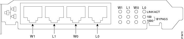
Figure 5-2 shows the 4-port inline network adapter port numbers, interface designations, and LEDs. The 2-port adapter is similar, but has only two ports and two sets of LEDs.
Figure 5-2 4-Port Inline Network Adapter Port Numbering and LEDs
|
|
Port WAN1; Group 1 WAN interface |
|
Port LAN1; Group 1 LAN interface |
|
|
Port WAN0; Group 0 WAN interface |
|
Port LAN0: Group 0 LAN interface |
The inline network adapter has three LEDs that correspond to each port (the W1 LEDs correspond to Port W1, and so forth). Table 5-1 describes the LEDs.
Inline Network Adapter Cabling Requirements
The inline network adapter ships with two types of cables: crossover and straight-through. When you connect the WAVE inline network adapter, the cable that you use depends on the link speed (Gigabit Ethernet or Fast Ethernet) and the types of devices (DCE or DTE) being connected.
Note ![]() You must retain the same link speed from one end of the connection to the other end. Inline adapter interfaces are able to autonegotiate link speeds. If you configure any of your connecting interfaces for Fast Ethernet (whether on a switch or a router), your WAVE inline adapter uses Fast Ethernet. If you configure any of your connecting interfaces for Gigabit Ethernet, your WAVE inline adapter uses Gigabit Ethernet. Speed and duplex settings are port specific so that two inline ports can negotiate different speeds independently.
You must retain the same link speed from one end of the connection to the other end. Inline adapter interfaces are able to autonegotiate link speeds. If you configure any of your connecting interfaces for Fast Ethernet (whether on a switch or a router), your WAVE inline adapter uses Fast Ethernet. If you configure any of your connecting interfaces for Gigabit Ethernet, your WAVE inline adapter uses Gigabit Ethernet. Speed and duplex settings are port specific so that two inline ports can negotiate different speeds independently.
If you are connecting a WAVE inline appliance between two devices using Gigabit Ethernet, you can use either straight-through cables, crossover cables, or any combination of the two cable types, regardless of the type of device. However, for consistency, we recommend that you use straight-through cables for all Gigabit Ethernet connections.
Table 5-2 shows the cable requirements for WAVE appliance and non-WAVE appliance connections when you are using Gigabit Ethernet end to end.
Some switches support automatic medium-dependent interface crossover (MDIX). You can configure MDIX by using the mdix auto global configuration switch command. If your switch supports MDIX, you do not need to follow these cabling rules because MDIX automatically adjusts transmit and receive pairs when an incorrect cable type (crossover or straight-through) is installed on a 10/100 Fast Ethernet port. However, when you configure MDIX, you must also configure the port to use autosense (not manual selection of speed/duplex).

To connect the inline network adapter using the correct cables for Fast Ethernet connections, follow these steps:
Step 1 ![]() Determine the type of cable that you would use for a direct connection between your two end devices (without a WAVE inline network appliance connected between them) by using the following standard cabling rules:
Determine the type of cable that you would use for a direct connection between your two end devices (without a WAVE inline network appliance connected between them) by using the following standard cabling rules:
•![]() When you are directly connecting two network devices that are similar, such as two switches, use a crossover cable.
When you are directly connecting two network devices that are similar, such as two switches, use a crossover cable.
•![]() When you are directly connecting two network devices that are different, such as a switch and router, use a straight-through cable.
When you are directly connecting two network devices that are different, such as a switch and router, use a straight-through cable.
Note ![]() Because the inline network adapter has an internal crossover connection that becomes active when the InlineGroup interface is placed in mechanical bypass mode, you must decide which cable you would use to connect the two network devices directly, and then you must install the other cable type (on one side, usually the WAN side of the inline appliance) instead.
Because the inline network adapter has an internal crossover connection that becomes active when the InlineGroup interface is placed in mechanical bypass mode, you must decide which cable you would use to connect the two network devices directly, and then you must install the other cable type (on one side, usually the WAN side of the inline appliance) instead.
Table 5-3 shows the cable requirements for WAVE and non-WAVE connections when you are using Fast Ethernet end to end.
Step 2 ![]() Connect Fast Ethernet ports on both the LAN and the WAN sides of the WAVE inline appliance by using the following cable types:
Connect Fast Ethernet ports on both the LAN and the WAN sides of the WAVE inline appliance by using the following cable types:
•![]() On the LAN side of the connection, use a straight-through cable between the WAVE inline appliance and the network device.
On the LAN side of the connection, use a straight-through cable between the WAVE inline appliance and the network device.
•![]() On the WAN side of the connection, use the cable that is different from the cable that you would use to connect the two network devices directly (as determined in Step 1).
On the WAN side of the connection, use the cable that is different from the cable that you would use to connect the two network devices directly (as determined in Step 1).
For example, if you are connecting a router and a switch (two different devices) through the WAVE inline appliance, use a straight-through cable on the LAN side of the connection and use a crossover cable on the WAN side of the connection. (If you were connecting the two different devices directly, you would use a straight-through cable, so use the crossover cable instead.)
If you are connecting two switches (or two similar devices), use straight-through cables on both the LAN and the WAN sides of the WAVE inline appliance.
Figure 5-3 through Figure 5-5 show which cables to use for the WAVE LAN and WAN connections between Fast Ethernet ports.
Installation Scenarios and Cabling Examples for Fast Ethernet Connections
WAVE appliances can be installed physically between two network devices (such as the branch office router and branch office LAN switch) by connecting the WAVE inline network adapter ports to the network devices using the proper cables.
If you are connecting a WAVE inline appliance between two devices using Gigabit Ethernet, you can use either straight-through cables, crossover cables, or any combination of the two cable types, regardless of the type of device. This section shows cabling examples for Fast Ethernet connections only, because Fast Ethernet has specific cabling requirements.
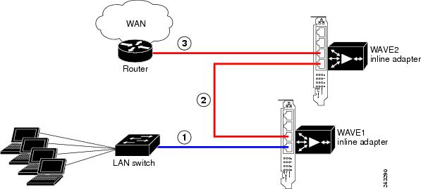
The inline network adapter has four ports that are divided into two inline groups (see the "Ports and LED Indicators" section). The WAVE appliance can be physically placed inline between two distinct network paths, creating redundant WAN links. (See Figure 5-3.)
Two WAVE appliances with inline network adapters can also be installed back-to-back in a serial fashion between two network devices for failover purposes. In this serial cluster configuration, if one WAVE appliance fails, the other WAVE appliance can provide optimization. (See Figure 5-4.)
Note ![]() When you connect two WAVE inline appliances to each other serially, always use a crossover cable between the two WAVE appliances. (See Figure 5-5.)
When you connect two WAVE inline appliances to each other serially, always use a crossover cable between the two WAVE appliances. (See Figure 5-5.)
Figure 5-3 Cabling for a Single Inline WAVE Appliance with Redundant WAN Connections
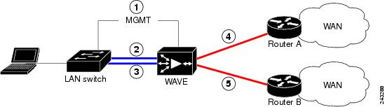
Figure 5-4 Cabling for Serial Cluster Inline WAVEs with a Single WAN Connection
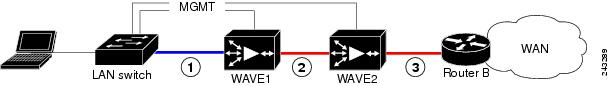
Figure 5-5 Cabling Between Two Inline WAVEs
 Feedback