- Preface
- Introduction to Cisco WAAS
- Planning Your WAAS Network
- Using Device Groups and Device Locations
- Configuring AppNav
- Configuring Traffic Interception
- Configuring Network Settings
- Configuring Administrative Login Authentication, Authorization, and Accounting
- Creating and Managing Administrator User Accounts and Groups
- Creating and Managing IP Access Control Lists for WAAS Devices
- Configuring Other System Settings
- Configuring File Services
- Configuring Application Acceleration
- Configuring Network Analysis Module
- Maintaining Your WAAS System
- Monitoring and Troubleshooting Your WAAS Network
- Configuring SNMP Monitoring
- Predefined Application Policies
- Transaction Log Format
- Index
Cisco Wide Area Application Services Configuration Guide (Software Version 6.1.1)
Bias-Free Language
The documentation set for this product strives to use bias-free language. For the purposes of this documentation set, bias-free is defined as language that does not imply discrimination based on age, disability, gender, racial identity, ethnic identity, sexual orientation, socioeconomic status, and intersectionality. Exceptions may be present in the documentation due to language that is hardcoded in the user interfaces of the product software, language used based on RFP documentation, or language that is used by a referenced third-party product. Learn more about how Cisco is using Inclusive Language.
- Updated:
- January 13, 2014
Chapter: Configuring Network Settings
- Configuring Network Interfaces
- Configuring a Standby Interface
- Configuring Multiple IP Addresses on a Single Interface
- Configuring Ethernet Interface Settings
- Configuring the Default Gateway
- Configuring Port-Channel Settings
- Configuring Interfaces for DHCP
- Modifying Virtual Interface Settings for a vWAAS Device
- Enabling or Disabling Optimization on WAAS Express Interfaces
- Enabling WAAS Service Insertion on AppNav-XE Device Interfaces
- Configuring Management Interface Settings
- Configuring a Jumbo MTU
- Configuring TCP Settings
- Configuring a Static IP Route
- Configuring CDP Settings
- Configuring the DNS Server
- Configuring Windows Name Services
Configuring Network Settings
This chapter describes how to configure basic network settings such as configuring additional network interfaces to support network traffic, creating port channel and standby interfaces, configuring optimization on Cisco Wide Area Application Services (WAAS) Express interfaces, specifying a default gateway and Domain Name System (DNS) servers, enabling the Cisco Discovery Protocol (CDP).

Note![]() Throughout this chapter, the term Cisco WAAS device is used to refer collectively to the WAAS Central Managers and Cisco Wide Area Application Engines (WAEs) in your network. The term WAE refers to WAE and WAVE appliances, SM-SRE modules running WAAS, and Cisco Virtual WAAS (vWAAS) instances.
Throughout this chapter, the term Cisco WAAS device is used to refer collectively to the WAAS Central Managers and Cisco Wide Area Application Engines (WAEs) in your network. The term WAE refers to WAE and WAVE appliances, SM-SRE modules running WAAS, and Cisco Virtual WAAS (vWAAS) instances.
This chapter contains the following sections:
- Configuring Network Interfaces
- Configuring TCP Settings
- Configuring a Static IP Route
- Configuring CDP Settings
- Configuring the DNS Server
- Configuring Windows Name Services
For information on configuring a bridge group for inline interfaces on an AppNav Controller Interface Module, see Configuring Inline Operation on ANCs in Chapter 5, “Configuring Traffic Interception,” or use the AppNav Cluster wizard, as described in Creating a New AppNav Cluster with the AppNav Cluster Wizard in Chapter 4, “Configuring AppNav.”
Configuring Network Interfaces
During initial setup, you choose an initial interface and either configure it for DHCP or gave it a static IP address, as described in the Cisco Wide Area Application Services Quick Configuration Guide.
From release 6.0, the following devices support IPv4 only, IPv6 only and dual stack configuration.
- WAVE-294/594/694/7541/7571/8541
- vWAAS on VMware ESX and ESXi hypervisor, vWAAS on ISR 4451(kWAAS)
- WAAS Express
This section describes how to configure additional interfaces using options for redundancy, load balancing, and performance optimization and also to modify previously configured settings on interfaces.
This section contains the following topics:
- Configuring a Standby Interface
- Configuring Multiple IP Addresses on a Single Interface
- Configuring Ethernet Interface Settings
- Configuring the Default Gateway
- Configuring Port-Channel Settings
- Configuring Interfaces for DHCP
- Modifying Virtual Interface Settings for a vWAAS Device
- Enabling or Disabling Optimization on WAAS Express Interfaces
- Enabling WAAS Service Insertion on AppNav-XE Device Interfaces
- Configuring Management Interface Settings
- Configuring a Jumbo MTU
We recommend that you use the WAAS Central Manager instead of the WAAS CLI to configure network settings. If you want to use the CLI, see the following commands in the Cisco Wide Area Application Services Command Reference : interface, ip address, port-channel, and primary-interface.
Network interfaces are named as follows on WAAS devices:
- WAE-512/612/7326—Have two inbuilt Ethernet interfaces named GigabitEthernet 1/0 and GigabitEthernet 2/0.
- WAVE-294/594/694/7541/7571/8541—Have two inbuilt Ethernet interfaces named GigabitEthernet 0/0 and GigabitEthernet 0/1. Additional interfaces on the Cisco Interface Module and AppNav Controller Interface Module are named GigabitEthernet 1/0 to 1/11 or TenGigabitEthernet 1/0 to 1/3, depending on the number and type of ports.
- NME-WAE devices—Have an internal interface to the router that is designated 1/0, and an external interface that is designated 2/0.SM-SRE devices—Have an internal interface to the router that is designated 1/0 and an external interface that is designated 2/0.
Note![]() We strongly recommend that you do not use half-duplex connections on the WAE or on routers, switches, or other devices. Half duplex impedes performance and should not be used. Check each Cisco WAE interface and the port configuration on the adjacent device (router, switch, firewall, and WAE) to verify that full duplex is configured.
We strongly recommend that you do not use half-duplex connections on the WAE or on routers, switches, or other devices. Half duplex impedes performance and should not be used. Check each Cisco WAE interface and the port configuration on the adjacent device (router, switch, firewall, and WAE) to verify that full duplex is configured.
When connecting an AppNav Controller to a Cisco Nexus 7000 Series switch, the interfaces on both devices must be set to the same autonegotiate setting: either both on or both off. If they are set differently, switch-link flapping may occur.
Note![]() On Cisco ISR-WAAS devices, you cannot configure the following from the WAAS Central Manager: network interfaces, ip addresses (IPv4 or IPv6), routes, default gateway, DNS servers, and jumbo maximum transmission unit (MTU). Use the router CLI to configure these.
On Cisco ISR-WAAS devices, you cannot configure the following from the WAAS Central Manager: network interfaces, ip addresses (IPv4 or IPv6), routes, default gateway, DNS servers, and jumbo maximum transmission unit (MTU). Use the router CLI to configure these.
Note![]() Layer 3 interfaces may drop bridge protocol data unit (BPDU) packets. However, this does not affect data traffic.
Layer 3 interfaces may drop bridge protocol data unit (BPDU) packets. However, this does not affect data traffic.
Configuring a Standby Interface
Using this procedure, you can configure a logical interface called a standby interface. After you configure this standby interface, you must associate physical or port-channel interfaces with the standby interface in order to create a standby group. In the WAAS Central Manager, you can create a standby group by assigning two interfaces to the standby group and assigning one as primary.
Standby interfaces remain unused unless a member interface that is in use fails. When an in-use network interface fails (because of cable trouble, Layer 2 switch failure, or other failure), the other member interface of the standby group changes its state to in use and starts to carry traffic and take the load off the failed interface. With the standby interface configuration, only one interface is in use at a given time.
To configure standby interfaces, you must assign two physical or two port-channel interface members to a standby group. The following operating considerations apply to standby groups:
- A standby group consists of two physical or two port-channel interfaces. (If you are configuring a WAAS device running a version earlier than 5.0, both interfaces must be physical interfaces.)
- The maximum number of standby groups on a WAAS device is two. When using a Cisco AppNav Controller Interface Module, you can have up to three standby groups.
- A standby group is assigned a unique standby IP address, shared by all members of the group.
- Configuring the duplex and speed settings of the standby group member interfaces provides better reliability.
- IP ACLs can be configured on physical interfaces that are members of a standby group.
- One interface in a standby group is designated as the primary standby interface. Only the primary interface uses the group IP address.
- If the in-use interface fails, another interface in its standby group takes over and carries the traffic.
- If all the members of a standby group fail, and then one recovers, the WAAS software brings up the standby group on the operational interface.
- The primary interface in a standby group can be changed at runtime. (The default action is to pre-empt the currently in-use interface if a different interface is made primary.)
- If a physical interface is a member of a standby group, it cannot also be a member of a port channel.
- If a device has only two interfaces, you cannot assign an IP address to both a standby group and a port channel. On such a device, only one logical interface can be configured with an IP address.
- The member interfaces of a standby group can be connected to different switches if you use a VLAN tagging protocol and assign the same VLAN tag to each interface.
- You cannot include a built-in Ethernet port and a port on a Cisco Interface Module in the same standby group.
Configuring a standby interface differs, depending on the version of the WAAS device that you are configuring. See one of the following topics:
Configuring a Standby Interface on a Device with Version 5.0 or Later
To configure a standby interface for devices with WAAS Version 5.0 or later, follow these steps:
Step 1![]() From the WAAS Central Manager menu, choose Devices > device-name.
From the WAAS Central Manager menu, choose Devices > device-name.
Step 2![]() Choose Configure > Network > Network Interfaces.
Choose Configure > Network > Network Interfaces.
The Network Interfaces window for the device appears. (See Figure 6-1.)
Figure 6-1 Network Interfaces for Device Window
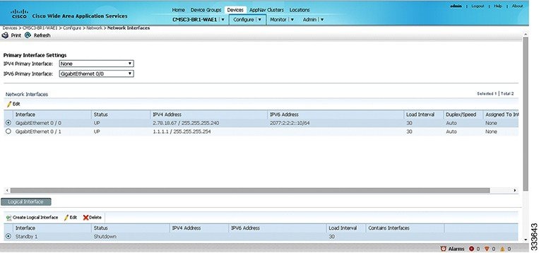
Step 3![]() In the taskbar of the lower area, click the Create Logical Interface icon.
In the taskbar of the lower area, click the Create Logical Interface icon.
The Create Logical Interface window appears.
Step 4![]() From the Logical Interface Type drop-down list, choose Standby and click OK.
From the Logical Interface Type drop-down list, choose Standby and click OK.
The window refreshes with fields for configuring the standby group settings.
Step 5![]() From the Standby Group Number drop-down list, choose a group number for the interface.
From the Standby Group Number drop-down list, choose a group number for the interface.
Step 6![]() (Optional) From the Bridge Group Number drop-down list, choose a bridge virtual interface (BVI) group number with which to associate this standby interface, or None. For more information on BVI, see Configuring Management Interface Settings.
(Optional) From the Bridge Group Number drop-down list, choose a bridge virtual interface (BVI) group number with which to associate this standby interface, or None. For more information on BVI, see Configuring Management Interface Settings.
Note![]() This configuration item is not supported on AppNav Controller Interface Module ports.
This configuration item is not supported on AppNav Controller Interface Module ports.
Step 7![]() (Optional) In the Description field, enter a description for the standby group.
(Optional) In the Description field, enter a description for the standby group.
Step 8![]() (Optional) Check the Shutdown check box to shut down the hardware interface. By default, this option is disabled.
(Optional) Check the Shutdown check box to shut down the hardware interface. By default, this option is disabled.
Step 9![]() (Optional) From the Load Interval drop-down list, choose the interval, in seconds, at which to poll the interface for statistics and calculate throughput. The default is 30 seconds.
(Optional) From the Load Interval drop-down list, choose the interval, in seconds, at which to poll the interface for statistics and calculate throughput. The default is 30 seconds.
Step 10![]() In the Address field, specify the IP address of the standby group.
In the Address field, specify the IP address of the standby group.
Step 11![]() In the Netmask field, specify the netmask of the standby group.
In the Netmask field, specify the netmask of the standby group.
Step 12![]() Under IPv6 Settings, manually assign an IPv6 address to the primary interface or select from the following options. If you select one of the following options, the IPv6 address field and subsequent secondary IPv6 address fields are not available.
Under IPv6 Settings, manually assign an IPv6 address to the primary interface or select from the following options. If you select one of the following options, the IPv6 address field and subsequent secondary IPv6 address fields are not available.
- Use Link Local - A unicast address that is automatically configured on an interface using the link-local prefix FE80::/10 and the interface identifier in the modified EUI-64 format. Using this address configuration option is sufficient for nodes on a link to communicate.
- Use Auto Config - To auto-configure an IPv6 global unicast address on the interface as per RFC 4862.
Step 13![]() In the Duplicate address Detection Attempts field enter a number between 0-600 to specify the number of attempts by which the duplicate address should be detected.
In the Duplicate address Detection Attempts field enter a number between 0-600 to specify the number of attempts by which the duplicate address should be detected.
Step 14![]() In the Assign Interfaces area, check the check boxes next to the two interfaces that you want to assign to this standby group and click the Assign taskbar icon. (To unassign any assigned interfaces, check the check box next to each interface that you want to unassign and click the Unassign taskbar icon.)
In the Assign Interfaces area, check the check boxes next to the two interfaces that you want to assign to this standby group and click the Assign taskbar icon. (To unassign any assigned interfaces, check the check box next to each interface that you want to unassign and click the Unassign taskbar icon.)
If you want to have two port-channel interfaces as members of the standby group, do not assign any interfaces here. When you create the port-channel interfaces, you assign the standby group number in that window.
Step 15![]() To assign one physical interface as the primary (active) interface in the standby group, ensure that it is the only interface that is checked, and then click the Enable Primary taskbar icon.
To assign one physical interface as the primary (active) interface in the standby group, ensure that it is the only interface that is checked, and then click the Enable Primary taskbar icon.
Configuring a Standby Interface on a Device Earlier than Version 5.0
To configure a standby interface for devices with WAAS versions earlier than 5.0, follow these steps:
Step 1![]() From the WAAS Central Manager menu, choose Devices > device-name.
From the WAAS Central Manager menu, choose Devices > device-name.
Step 2![]() Choose Configure > Network > Network Interfaces.
Choose Configure > Network > Network Interfaces.
The Network Interfaces window for the device appears.
Step 3![]() In the taskbar, click the Create New Interface icon.
In the taskbar, click the Create New Interface icon.
The Creating New Network Interface window appears.
Step 4![]() From the Port Type drop-down list, choose Standby.
From the Port Type drop-down list, choose Standby.
The window refreshes with fields for configuring the standby group settings.
Step 5![]() From the Standby Group Number drop-down list, choose a group number for the interface.
From the Standby Group Number drop-down list, choose a group number for the interface.
Step 6![]() (Optional) In the Description field, enter a description for the standby group.
(Optional) In the Description field, enter a description for the standby group.
Step 7![]() In the Address field, specify the IP address of the standby group.
In the Address field, specify the IP address of the standby group.
Step 8![]() In the Netmask field, specify the netmask of the standby group.
In the Netmask field, specify the netmask of the standby group.
Step 9![]() (Optional) Check the Shutdown check box to shut down the hardware interface. By default, this option is disabled.
(Optional) Check the Shutdown check box to shut down the hardware interface. By default, this option is disabled.
Step 10![]() In the Default Gateway field, enter the default gateway IP address. If an interface is configured for DHCP, then this field is read only.
In the Default Gateway field, enter the default gateway IP address. If an interface is configured for DHCP, then this field is read only.
Step 11![]() (Optional) From the Bridge Group Number drop-down list, choose a bridge virtual interface (BVI) group number with which to associate this standby interface, or choose None. For more information on BVI, see Configuring Management Interface Settings.
(Optional) From the Bridge Group Number drop-down list, choose a bridge virtual interface (BVI) group number with which to associate this standby interface, or choose None. For more information on BVI, see Configuring Management Interface Settings.
Step 13![]() Configure the physical interface members, as described in Assigning Physical Interfaces to a Standby Group.
Configure the physical interface members, as described in Assigning Physical Interfaces to a Standby Group.
Note![]() After you create the standby interface, assign two physical interfaces to the standby group.
After you create the standby interface, assign two physical interfaces to the standby group.
Assigning Physical Interfaces to a Standby Group
After you configure a logical standby interface for a device with a WAAS version earlier than 5.0, configure the standby group by assigning physical interfaces to the standby group and setting one physical interface as the primary standby interface. The primary interface in the standby group uses the standby group IP address. You must have a standby interface configured before you can set it as primary. (See Configuring a Standby Interface.)
You can assign an interface to a standby group only if the interface does not have an IP address assigned, and uses the IP address of the standby group.
Note![]() Removing a physical interface from standby group 2 on all WAAS device models may cause network disruption for up to 30 seconds. Additionally, removing a physical interface from standby group 1 on device model WAE-612 may cause network disruption for up to 30 seconds. The best practice is to make such changes when traffic interception is disabled, or at a time when traffic disruption is acceptable.
Removing a physical interface from standby group 2 on all WAAS device models may cause network disruption for up to 30 seconds. Additionally, removing a physical interface from standby group 1 on device model WAE-612 may cause network disruption for up to 30 seconds. The best practice is to make such changes when traffic interception is disabled, or at a time when traffic disruption is acceptable.
To associate an interface with a standby group and set it as the primary standby interface, follow these steps:
Step 1![]() From the WAAS Central Manager menu, choose Devices > device-name.
From the WAAS Central Manager menu, choose Devices > device-name.
Step 2![]() Choose Configure > Network > Network Interfaces. The Network Interfaces window for the device appears.
Choose Configure > Network > Network Interfaces. The Network Interfaces window for the device appears.
Step 3![]() Click the Edit icon next to the physical interface that you want to assign to a standby group. The Interface Settings window appears.
Click the Edit icon next to the physical interface that you want to assign to a standby group. The Interface Settings window appears.
Note![]() Choose a physical interface, not a logical interface (standby, port channel, or BVI), in this step.
Choose a physical interface, not a logical interface (standby, port channel, or BVI), in this step.
Step 4![]() Complete the following steps to assign the interface to a standby group and specify it as the primary standby interface:
Complete the following steps to assign the interface to a standby group and specify it as the primary standby interface:
a.![]() In the Port Type To Assign drop-down list, choose Standby.
In the Port Type To Assign drop-down list, choose Standby.
b.![]() Check either the Join Standby Group 1 or the Join Standby Group 2 check box. (Only one check box is shown if only one standby interface has been defined.)
Check either the Join Standby Group 1 or the Join Standby Group 2 check box. (Only one check box is shown if only one standby interface has been defined.)
c.![]() (Optional) Check the Standby Primary check box if you want this physical interface to be the primary (active) interface in the standby group.
(Optional) Check the Standby Primary check box if you want this physical interface to be the primary (active) interface in the standby group.
Configuring Multiple IP Addresses on a Single Interface
You can configure up to four secondary IP addresses on a single interface. This configuration allows the device to be present in more than one subnet and can be used to optimize the response time because it allows the data to go directly from the WAAS device to the client that is requesting the information without being redirected through a router. The WAAS device becomes visible to the client because both are configured on the same subnet.
Configuring multiple IP addresses is not supported on AppNav Controller Interface Module ports.
To configure multiple IP addresses on a single interface, follow these steps:
Step 1![]() From the WAAS Central Manager menu, choose Devices > device-name.
From the WAAS Central Manager menu, choose Devices > device-name.
Step 2![]() Choose Configure > Network > Network Interfaces. The Network Interfaces listing window appears.
Choose Configure > Network > Network Interfaces. The Network Interfaces listing window appears.
Step 3![]() Choose the physical interface that you want to modify and click the Edit taskbar icon. (For devices using WAAS versions earlier than 5.0, click the Edit icon next to the interface.)
Choose the physical interface that you want to modify and click the Edit taskbar icon. (For devices using WAAS versions earlier than 5.0, click the Edit icon next to the interface.)
The Interface Settings window appears.
Note![]() Do not choose a standby or port-channel interface in this step. You cannot configure multiple IP addresses on these types of interfaces.
Do not choose a standby or port-channel interface in this step. You cannot configure multiple IP addresses on these types of interfaces.
Step 4![]() In the Secondary Address and Secondary Netmask fields 1 through 4, enter up to four different IP addresses and secondary netmasks for the interface.
In the Secondary Address and Secondary Netmask fields 1 through 4, enter up to four different IP addresses and secondary netmasks for the interface.
Step 5![]() Click OK. (For devices using WAAS versions earlier than 5.0, click Submit).
Click OK. (For devices using WAAS versions earlier than 5.0, click Submit).
Configuring Ethernet Interface Settings
Modifying Physical Ethernet Interface Settings
To modify the settings of a physical Ethernet interface, follow these steps:
Step 1![]() From the WAAS Central Manager menu, choose Devices > device-name.
From the WAAS Central Manager menu, choose Devices > device-name.
Step 2![]() Choose Configure > Network > Network Interfaces.
Choose Configure > Network > Network Interfaces.
The Network Interfaces window appears, listing the configured network interfaces.
Note![]() On NME-WAE devices, the internal interface to the router is designated slot 1, port 0, and the external interface is designated slot 2, port 0. For NME-WAE configuration details, see the document Configuring Cisco WAAS Network Modules for Cisco Access Routers.
On NME-WAE devices, the internal interface to the router is designated slot 1, port 0, and the external interface is designated slot 2, port 0. For NME-WAE configuration details, see the document Configuring Cisco WAAS Network Modules for Cisco Access Routers.
On ISR-WAAS devices you cannot configure the network interfaces from the Central Manager.
Step 3![]() Choose the physical interface that you want to modify, and click the Edit taskbar icon. (For devices using WAAS versions earlier than 5.0, click the Edit icon next to the interface.)
Choose the physical interface that you want to modify, and click the Edit taskbar icon. (For devices using WAAS versions earlier than 5.0, click the Edit icon next to the interface.)
The Interface Settings window appears, displaying the interface configurations on a particular slot and port. The interface type, slot, and port are determined by the hardware.
Note![]() When configuring the internal interface (GigabitEthernet 1/0) on an NME-WAE device, you cannot change the following fields or check boxes: Port Channel Number, AutoSense, Speed, Mode, Address, Netmask, Use DHCP, and Standby Group. If you attempt to change these values, the Central Manager displays an error when you click OK. These settings for the internal interface can be configured only through the host router CLI. For NME-WAE details, see the document Configuring Cisco WAAS Network Modules for Cisco Access Routers.
When configuring the internal interface (GigabitEthernet 1/0) on an NME-WAE device, you cannot change the following fields or check boxes: Port Channel Number, AutoSense, Speed, Mode, Address, Netmask, Use DHCP, and Standby Group. If you attempt to change these values, the Central Manager displays an error when you click OK. These settings for the internal interface can be configured only through the host router CLI. For NME-WAE details, see the document Configuring Cisco WAAS Network Modules for Cisco Access Routers.
Step 4![]() (Optional) In the Description field, enter a description for the interface.
(Optional) In the Description field, enter a description for the interface.
Step 5![]() (Optional) Check the Use CDP check box to enable the Cisco Discovery Protocol (CDP) on an interface.
(Optional) Check the Use CDP check box to enable the Cisco Discovery Protocol (CDP) on an interface.
When enabled, CDP obtains protocol addresses of neighboring devices and discovers the platform of those devices. It also shows information about the interfaces used by your router.
Configuring CDP from the CDP Settings window enables CDP globally on all the interfaces. For information on configuring CDP settings, see Configuring CDP Settings.
Step 6![]() (Optional) Check the Shutdown check box to shut down the hardware interface.
(Optional) Check the Shutdown check box to shut down the hardware interface.
Step 7![]() (Optional) From the Load Interval drop-down list, choose the interval, in seconds, at which to poll the interface for statistics and calculate throughput. The default is 30 seconds. (The Load Interval item is not shown for devices using WAAS versions earlier than 5.0.)
(Optional) From the Load Interval drop-down list, choose the interval, in seconds, at which to poll the interface for statistics and calculate throughput. The default is 30 seconds. (The Load Interval item is not shown for devices using WAAS versions earlier than 5.0.)
Step 8![]() (Optional) Check the AutoSense check box to set the interface to autonegotiate the speed and mode. (This setting is not available on interfaces on some Cisco Interface Modules.)
(Optional) Check the AutoSense check box to set the interface to autonegotiate the speed and mode. (This setting is not available on interfaces on some Cisco Interface Modules.)
Checking this check box disables the manual Speed and Mode drop-down list settings.
Note![]() When autosense is on, manual configurations are overridden. You must reboot the WAAS device to start autosensing.
When autosense is on, manual configurations are overridden. You must reboot the WAAS device to start autosensing.
Step 9![]() (Optional) Manually configure the interface transmission speed and mode settings as follows (these settings are not available on interfaces on some Cisco Interface Modules):
(Optional) Manually configure the interface transmission speed and mode settings as follows (these settings are not available on interfaces on some Cisco Interface Modules):
a.![]() Uncheck the AutoSense check box.
Uncheck the AutoSense check box.
b.![]() From the Speed drop-down list, choose a transmission speed (10, 100, 1000, or 10000 Mbps). You must choose 1000 Mbps for fiber Gigabit Ethernet interfaces on a Cisco Interface Module.
From the Speed drop-down list, choose a transmission speed (10, 100, 1000, or 10000 Mbps). You must choose 1000 Mbps for fiber Gigabit Ethernet interfaces on a Cisco Interface Module.
c.![]() From the Mode drop-down list, choose a transmission mode (full-duplex or half-duplex). You must choose full-duplex for fiber Gigabit Ethernet interfaces on a Cisco Interface Module. This configuration item is not supported on AppNav Controller Interface Module ports.
From the Mode drop-down list, choose a transmission mode (full-duplex or half-duplex). You must choose full-duplex for fiber Gigabit Ethernet interfaces on a Cisco Interface Module. This configuration item is not supported on AppNav Controller Interface Module ports.
Full-duplex transmission allows data to travel in both directions at the same time through an interface or a cable. A half-duplex setting ensures that data travels only in one direction at any given time. Although full duplex is faster, the interfaces sometimes cannot operate effectively in this mode. If you encounter excessive collisions or network errors, you may configure the interface for half duplex rather than full duplex.
Note![]() We strongly recommend that you do not use half-duplex connections on the WAE or on routers, switches, or other devices. Half duplex impedes performance and should not be used. Check each Cisco WAE interface and the port configuration on the adjacent device (router, switch, firewall, and WAE) to verify that full duplex is configured.
We strongly recommend that you do not use half-duplex connections on the WAE or on routers, switches, or other devices. Half duplex impedes performance and should not be used. Check each Cisco WAE interface and the port configuration on the adjacent device (router, switch, firewall, and WAE) to verify that full duplex is configured.
Step 10![]() Specify a value (in bytes) in the MTU field to set the interface MTU size.
Specify a value (in bytes) in the MTU field to set the interface MTU size.
The range is 576 to 1500 bytes. The MTU is the largest size of IP datagram that can be transferred using a specific data link connection.
If the interface has a IPv6 configuration, the MTU range is between 1280-1500 bytes.
Note![]() The MTU field is not editable if the interface is assigned to a standby or port-channel group, or if a system jumbo MTU is configured.
The MTU field is not editable if the interface is assigned to a standby or port-channel group, or if a system jumbo MTU is configured.
Step 11![]() (Optional) Check the Use DHCP check box to obtain an interface IP address through DHCP. Checking this box hides the IP address and Netmask fields. (For devices with WAAS versions earlier than 5.0, these fields are not hidden, but are disabled.) This configuration item is not supported on AppNav Controller Interface Module ports.
(Optional) Check the Use DHCP check box to obtain an interface IP address through DHCP. Checking this box hides the IP address and Netmask fields. (For devices with WAAS versions earlier than 5.0, these fields are not hidden, but are disabled.) This configuration item is not supported on AppNav Controller Interface Module ports.
Optionally, supply a hostname in the Hostname field and a client ID in the Client Id field.
Step 12![]() In the Address field, enter a new IP address to change the interface IP address.
In the Address field, enter a new IP address to change the interface IP address.
Step 13![]() In the Netmask field, enter a new netmask to change the interface netmask.
In the Netmask field, enter a new netmask to change the interface netmask.
Step 14![]() (Optional) Enter up to four secondary IP addresses and corresponding subnet masks in the Secondary Address and Secondary Netmask fields. These fields are not supported on AppNav Controller Interface Module ports.
(Optional) Enter up to four secondary IP addresses and corresponding subnet masks in the Secondary Address and Secondary Netmask fields. These fields are not supported on AppNav Controller Interface Module ports.
Configuring multiple IP addresses allows the device to be present in more than one subnet and can be used to optimize the response time because it allows the data to go directly from the WAAS device to the client that is requesting the information without being redirected through a router. The WAAS device becomes visible to the client because both are configured on the same subnet.
Step 15![]() In the Default Gateway field, enter the default gateway IP address. If an interface is configured for DHCP, this field is read only. (The Default Gateway field is not shown for devices using WAAS versions 5.0 or later; configure it as described in Configuring the Default Gateway.)
In the Default Gateway field, enter the default gateway IP address. If an interface is configured for DHCP, this field is read only. (The Default Gateway field is not shown for devices using WAAS versions 5.0 or later; configure it as described in Configuring the Default Gateway.)
Step 16![]() (Optional) From the Inbound ACL drop-down list, choose an IP ACL to apply to inbound packets.
(Optional) From the Inbound ACL drop-down list, choose an IP ACL to apply to inbound packets.
The drop-down list contains all the IP ACLs that you configured in the system.
Step 17![]() (Optional) From the Outbound ACL drop-down list, choose an IP ACL to apply to outbound packets.
(Optional) From the Outbound ACL drop-down list, choose an IP ACL to apply to outbound packets.
Step 18![]() Under IPv6 Settings, manually assign an IPv6 address to the primary interface or select from the following options. If you select one of the following options, the IPv6 address field and subsequent secondary IPv6 address fields are not available.
Under IPv6 Settings, manually assign an IPv6 address to the primary interface or select from the following options. If you select one of the following options, the IPv6 address field and subsequent secondary IPv6 address fields are not available.
- Use Link Local - A unicast address that is automatically configured on an interface using the link-local prefix FE80::/10 and the interface identifier in the modified EUI-64 format. Using this address configuration option is sufficient for nodes on a link to communicate.
- Use Auto Config - To auto-configure an IPv6 global unicast address on the interface as per RFC 4862.
- Use DHCP - To obtain an interface IP address through DHCP.
Step 19![]() In the Duplicate address Detection Attempts field enter a number between 0-600 to specify the number of attempts by which the duplicate address should be detected.
In the Duplicate address Detection Attempts field enter a number between 0-600 to specify the number of attempts by which the duplicate address should be detected.
Step 20![]() Click OK. (For devices using WAAS versions earlier than 5.0, click Submit.)
Click OK. (For devices using WAAS versions earlier than 5.0, click Submit.)
Note![]() Changing the interface transmission speed, duplex mode, or MTU may cause network disruption for up to 30 seconds. The best practice is to make such changes when traffic interception is disabled or at a time when traffic disruption is acceptable.
Changing the interface transmission speed, duplex mode, or MTU may cause network disruption for up to 30 seconds. The best practice is to make such changes when traffic interception is disabled or at a time when traffic disruption is acceptable.
Configuring Flow Control on 1 GB/s and Faster Ethernet Ports
For Ethernet ports that run at 1 Gb/s or faster, you can enable or disable the port’s ability to send and receive flow-control pause frames. For Ethernet ports that run slower than 1 Gb/s, you can enable or disable only the port’s ability to receive flow-control pause frames.
Note![]() We recommend that you enable flow control on the Nexus 7000 and 6500 Series models when WAAS IOM onboard NIC are directly attached to the Nexus 7000 and 6500 Series models, and input packet drops are seen.
We recommend that you enable flow control on the Nexus 7000 and 6500 Series models when WAAS IOM onboard NIC are directly attached to the Nexus 7000 and 6500 Series models, and input packet drops are seen.
There are three options for enabling flow control for the local port:
- Fully enable the local port to send or receive frames regardless of the flow-control setting of the remote port,
- Set the local port to use the same setting you have specified for the remote port.
- Set a combination of the two states for the local and remote ports.
Note![]() If you enable flow control on both the local and the remote Ethernet port, or you set a specified flow control of the remote port only, or set a combination of these states—flow control is enabled for those ports.
If you enable flow control on both the local and the remote Ethernet port, or you set a specified flow control of the remote port only, or set a combination of these states—flow control is enabled for those ports.
Note![]() For Ethernet ports that run at 10 GB/s or faster, you cannot used the specified state for the send/receive parameter.
For Ethernet ports that run at 10 GB/s or faster, you cannot used the specified state for the send/receive parameter.
Before you configure flow control:
Before you being the following procedure, verify these conditions:
- Verify that the remote port that has the corresponding setting for the local port has the flow control that you need.
- If you want the local port to send flow-control pause frames, verify that the remote port has a Receive parameter set to On or Desired.
- If you want the local port to receive flow-control frames, verify that the remote port has a Send parameter set to On or Desired.
- If you do not want to use flow control, set the remote port’s Send and Receive parameters to Off.
To configure flow control for 1 GB/s and faster Ethernet ports, follow these steps:
Step 1![]() Enter Configuration mode for the terminal, using the config terminal command.
Enter Configuration mode for the terminal, using the config terminal command.
Step 2![]() Specify an Ethernet interface to configure, using the interface ethernet slot/port command.
Specify an Ethernet interface to configure, using the interface ethernet slot/port command.
The interface ethernet slot/port command enters the terminal into Interface Configuration mode.
Step 3![]() Specify the flow-control setting for ports, using the flowcontrol command.
Specify the flow-control setting for ports, using the flowcontrol command.
Parameters for this command are send/receive and desired/on/off.
- You can set the Send parameter only for ports running at 1000 MB/s or faster.
- You can set the Receive parameter for ports running at any speed.
Step 4![]() Display the interface status, using the show interface gigabitEthernet slot/port command.
Display the interface status, using the show interface gigabitEthernet slot/port command.
The interface status includes the flow-control parameters.
The following is sample output from the show interface gigabitEthernet slot/port command:
Step 5![]() Display the flow control status for all Ethernet ports, using the show interface flowcontrol command.
Display the flow control status for all Ethernet ports, using the show interface flowcontrol command.
Step 6![]() Exit Interface mode, using the exit command.
Exit Interface mode, using the exit command.
Step 7![]() (Optional) Copy the running configuration to the startup configuration, using the copy running-config startup-config command.
(Optional) Copy the running configuration to the startup configuration, using the copy running-config startup-config command.
Configuring the Default Gateway
On WAAS devices with Version 5.0 or later, configure the default gateway as follows:
Step 1![]() From the WAAS Central Manager menu, choose Devices > device-name.
From the WAAS Central Manager menu, choose Devices > device-name.
Step 2![]() Choose Configure > Network > Default Gateway.
Choose Configure > Network > Default Gateway.
The Default Gateway window appears with fields for IPv4 and IPv6.
Step 3![]() In the Default Gateway field, enter the default gateway IP address( either IPv4 or IPv6 address).
In the Default Gateway field, enter the default gateway IP address( either IPv4 or IPv6 address).
To configure a default gateway from the CLI, use the ip default-gateway global configuration or the ipv6 default-gateway address command.
On WAAS devices with versions earlier than 5.0, the default gateway should be configured within the interface settings for each interface.
Note![]() On ISR-WAAS devices, you cannot configure the default gateway from the Central Manager.
On ISR-WAAS devices, you cannot configure the default gateway from the Central Manager.
Configuring Port-Channel Settings
The WAAS software supports grouping of up to four (eight on AppNav Controller Interface Modules) physical network interfaces into one logical interface called a port channel. After you configure this port-channel interface, you must associate physical interfaces with the port channel.
You can configure up to four port-channel interfaces (seven on AppNav Controller Interface Modules). This capability also provides interoperability with Cisco routers, switches, and other networking devices or hosts supporting EtherChannel, load balancing, automatic failure detection, and recovery based on each interface’s current link status. EtherChannel is also referred to as a port channel.
You can use a port channel in standby interface, or as a member of an inline bridge group on an AppNav Controller Interface Module. For more information on configuring a BVI, see Configuring Management Interface Settings. The following operating considerations apply to a port-channel virtual interface:
- A physical interface can be a member of a port channel or a standby group, but not both.
- You cannot assign an IP address to both a port channel and a standby group. Only one logical interface can be configured with an IP address.
- All port-channel member interfaces must have the same port bandwidth.
- Port-channel settings are not applicable to vWAAS devices.
- You cannot include a built-in Ethernet port and a port on a Cisco Interface Module in the same port-channel interface.
Note![]() You must disable autoregistration if the device has only two interfaces and both device interfaces are configured as port-channel interfaces.
You must disable autoregistration if the device has only two interfaces and both device interfaces are configured as port-channel interfaces.
Configuring a port-channel interface differs, depending on the version of the WAAS device that you are configuring. See one of the following topics:
Configuring a Port-Channel Interface on a Device with Version 5.0 or Later
To configure a port-channel interface for devices with WAAS Version 5.0 or later, follow these steps:
Step 1![]() From the WAAS Central Manager menu, choose Devices > device-name.
From the WAAS Central Manager menu, choose Devices > device-name.
Step 2![]() Choose Configure > Network > Network Interfaces. The Network Interfaces window for the device appears.
Choose Configure > Network > Network Interfaces. The Network Interfaces window for the device appears.
Step 3![]() In the taskbar of the lower area, click the Create Logical Interface icon. The Create Logical Interface window appears.
In the taskbar of the lower area, click the Create Logical Interface icon. The Create Logical Interface window appears.
Step 4![]() From the Logical Interface Type drop-down list, choose PortChannel and click OK. The window refreshes with fields for configuring the port-channel interface settings.
From the Logical Interface Type drop-down list, choose PortChannel and click OK. The window refreshes with fields for configuring the port-channel interface settings.
Step 5![]() From the Port Channel Number drop-down list, choose a number for the interface.
From the Port Channel Number drop-down list, choose a number for the interface.
Step 6![]() (Optional) From the Bridge Group Number drop-down list, choose a bridge group number with which to associate this interface, or choose None. The bridge group number can be associated with a BVI or an inline bridge group defined on an AppNav Controller.
(Optional) From the Bridge Group Number drop-down list, choose a bridge group number with which to associate this interface, or choose None. The bridge group number can be associated with a BVI or an inline bridge group defined on an AppNav Controller.
Step 7![]() (Optional) From the Standby Group Number drop-down list, choose a standby group number with which to associate this interface, or choose None.
(Optional) From the Standby Group Number drop-down list, choose a standby group number with which to associate this interface, or choose None.
You must create the standby group with no assigned interfaces before it appears as a choice in this list.
Step 8![]() (Optional) In the Description field, enter a description for the interface.
(Optional) In the Description field, enter a description for the interface.
Step 9![]() (Optional) Check the Shutdown check box to shut down the hardware interface. By default, this option is disabled.
(Optional) Check the Shutdown check box to shut down the hardware interface. By default, this option is disabled.
If you plan to assign this port-channel interface to a standby interface, check this check box.
Step 10![]() (Optional) From the Load Interval drop-down list, choose the interval, in seconds, at which to poll the interface for statistics and calculate throughput. The default is 30 seconds.
(Optional) From the Load Interval drop-down list, choose the interval, in seconds, at which to poll the interface for statistics and calculate throughput. The default is 30 seconds.
Step 11![]() In the Address field, specify the IP address of the interface.
In the Address field, specify the IP address of the interface.
If you are assigning this port-channel interface to a standby group, do not configure an IP address or netmask. The standby group supplies the IP address and netmask.
Step 12![]() In the Netmask field, specify the netmask of the interface.
In the Netmask field, specify the netmask of the interface.
Step 13![]() (Optional) From the Inbound ACL drop-down list, choose an IP ACL to apply to inbound packets.
(Optional) From the Inbound ACL drop-down list, choose an IP ACL to apply to inbound packets.
The drop-down list contains all the IP ACLs that you configured in the system.
Step 14![]() (Optional) From the Outbound ACL drop-down list, choose an IP ACL to apply to outbound packets.
(Optional) From the Outbound ACL drop-down list, choose an IP ACL to apply to outbound packets.
Step 15![]() Under IPv6 Settings, manually assign an IPv6 address to the primary interface or select from the following options. If you select one of the following options, the IPv6 address field and subsequent secondary IPv6 address fields are not available.
Under IPv6 Settings, manually assign an IPv6 address to the primary interface or select from the following options. If you select one of the following options, the IPv6 address field and subsequent secondary IPv6 address fields are not available.
- Use Link Local - A unicast address that is automatically configured on an interface using the link-local prefix FE80::/10 and the interface identifier in the modified EUI-64 format. Using this address configuration option is sufficient for nodes on a link to communicate.
- Use Auto Config - To auto-configure an IPv6 global unicast address on the interface as per RFC 4862.
Step 16![]() In the Duplicate address Detection Attempts field enter a number between 0-600 to specify the number of attempts by which the duplicate address should be detected.
In the Duplicate address Detection Attempts field enter a number between 0-600 to specify the number of attempts by which the duplicate address should be detected.
Step 17![]() In the Assign Interfaces area, click the check box next to the interfaces that you want to assign to this port channel and click the Assign taskbar icon. To unassign assigned interfaces, check the check box next to each interface that you want to unassign and click the Unassign taskbar icon.
In the Assign Interfaces area, click the check box next to the interfaces that you want to assign to this port channel and click the Assign taskbar icon. To unassign assigned interfaces, check the check box next to each interface that you want to unassign and click the Unassign taskbar icon.
If you plan to assign this port-channel interface to a standby interface, do not assign interfaces until after the port channel is assigned to the standby interface.
Configuring a Port-Channel Interface on a Device Earlier than Version 5.0
To configure a port-channel interface for devices with WAAS versions earlier than 5.0, follow these steps:
Step 1![]() From the WAAS Central Manager menu, choose Devices > device-name.
From the WAAS Central Manager menu, choose Devices > device-name.
Step 2![]() Choose Configure > Network > Network Interfaces. The Network Interfaces window appears, listing all the interfaces for the chosen device.
Choose Configure > Network > Network Interfaces. The Network Interfaces window appears, listing all the interfaces for the chosen device.
Step 3![]() In the taskbar, click the Create New Interface icon. The Creating New Network Interface window appears.
In the taskbar, click the Create New Interface icon. The Creating New Network Interface window appears.
Step 4![]() From the Port Type drop-down list, choose PortChannel.
From the Port Type drop-down list, choose PortChannel.
The window refreshes and provides fields for configuring the network interface settings.
Step 5![]() From the Port Channel Number drop-down list, choose the number of the port-channel interface. Up to four port channels are supported, depending on the WAAS device model and installed interface module.
From the Port Channel Number drop-down list, choose the number of the port-channel interface. Up to four port channels are supported, depending on the WAAS device model and installed interface module.
Step 6![]() (Optional) In the Description field, enter a description for the port channel.
(Optional) In the Description field, enter a description for the port channel.
Step 7![]() (Optional) Check the Shutdown check box to shut down this interface. By default, this option is disabled.
(Optional) Check the Shutdown check box to shut down this interface. By default, this option is disabled.
Step 8![]() In the Default Gateway field, enter the default gateway IP address.
In the Default Gateway field, enter the default gateway IP address.
Step 9![]() In the Address field, specify the IP address of the interface.
In the Address field, specify the IP address of the interface.
Step 10![]() In the Netmask field, specify the netmask of the interface.
In the Netmask field, specify the netmask of the interface.
Step 11![]() (Optional) From the Inbound ACL drop-down list, choose an IP ACL to apply to inbound packets.
(Optional) From the Inbound ACL drop-down list, choose an IP ACL to apply to inbound packets.
The drop-down list contains all the IP ACLs that you configured in the system.
Step 12![]() (Optional) From the Outbound ACL drop-down list, choose an IP ACL to apply to outbound packets.
(Optional) From the Outbound ACL drop-down list, choose an IP ACL to apply to outbound packets.
Step 14![]() Configure the physical interface members as described in Assigning Physical Interfaces to a Port Channel.
Configure the physical interface members as described in Assigning Physical Interfaces to a Port Channel.
Note![]() After you create the port-channel interface, assign physical interfaces to the port channel.
After you create the port-channel interface, assign physical interfaces to the port channel.
Assigning Physical Interfaces to a Port Channel
After you have configured a logical port-channel interface, you must assign multiple physical interfaces to the port channel. You can assign up to four physical interfaces to one port-channel interface, depending on the WAAS device.
You can assign an interface to a port channel only if the interface does not have an IP address assigned, and uses the IP address of the port channel.
You cannot combine built-in Ethernet ports with ports on a Cisco Interface Module into the same port-channel interface.
Note![]() Removing a physical interface from a port channel on device model WAE-612 may cause network disruption for up to 30 seconds. The best practice is to make such changes when traffic interception is disabled or at a time when traffic disruption is acceptable.
Removing a physical interface from a port channel on device model WAE-612 may cause network disruption for up to 30 seconds. The best practice is to make such changes when traffic interception is disabled or at a time when traffic disruption is acceptable.
To add an interface to a port channel, follow these steps:
Step 1![]() From the WAAS Central Manager menu, choose Devices > device-name.
From the WAAS Central Manager menu, choose Devices > device-name.
Step 2![]() Choose Configure > Network > Network Interfaces. The Network Interfaces window for the device appears.
Choose Configure > Network > Network Interfaces. The Network Interfaces window for the device appears.
Step 3![]() Click the Edit icon next to the physical interface that you want to assign to a port channel. The Modifying Network Interface window appears.
Click the Edit icon next to the physical interface that you want to assign to a port channel. The Modifying Network Interface window appears.
Choose a physical interface, not a logical interface (standby, port channel, or BVI), in this step.
Step 4![]() Complete the following steps to assign the interface to a port channel:
Complete the following steps to assign the interface to a port channel:
a.![]() From the Port Type To Assign drop-down list, choose PortChannel.
From the Port Type To Assign drop-down list, choose PortChannel.
b.![]() From the Port Channel Number drop-down list, choose the number of the port channel to which you want to add the physical interface.
From the Port Channel Number drop-down list, choose the number of the port channel to which you want to add the physical interface.
Configuring a Load-Balancing Method for Port-Channel Interfaces
Before you configure load balancing, ensure that you have configured the port-channel settings described in Configuring Port-Channel Settings.
To configure load balancing, follow these steps:
Step 1![]() From the WAAS Central Manager menu, choose Devices > device-name ( or Device Groups > device-group-name).
From the WAAS Central Manager menu, choose Devices > device-name ( or Device Groups > device-group-name).
Step 2![]() Choose Configure > Network > Port Channel.
Choose Configure > Network > Port Channel.
Step 3![]() From the Load Balancing Method drop-down list, choose a load-balancing method:
From the Load Balancing Method drop-down list, choose a load-balancing method:
- src-dst-ip-port —The distribution function is based on a combination of source and destination IP addresses and ports. This load-balancing method is available only on devices running Version 4.4.1 and later.
- src-dst-ip —The distribution function is based on a combination of source and destination IP addresses. This load-balancing method is available only on devices running Version 5.0.1 and later.
- round-robin —Round robin allows traffic to be distributed evenly among all the interfaces in the channel group. This load-balancing method is available only on devices running versions earlier than 4.4.1.
To configure a load-balancing method from the CLI, use the port-channel global configuration command.
Note![]() To configure devices running previous versions of WAAS, a device group can be configured with a load-balancing method supported only by previous WAAS software versions. When viewing the Port Channel Settings window for Version 4.4.1 or later for a device that gets its settings from such a device group, you may see an unsupported load-balancing method listed. However, a Version 4.4.1 or later device supports only the load-balancing methods as described above, regardless of what the device group or device configuration window shows for the setting.
To configure devices running previous versions of WAAS, a device group can be configured with a load-balancing method supported only by previous WAAS software versions. When viewing the Port Channel Settings window for Version 4.4.1 or later for a device that gets its settings from such a device group, you may see an unsupported load-balancing method listed. However, a Version 4.4.1 or later device supports only the load-balancing methods as described above, regardless of what the device group or device configuration window shows for the setting.
Configuring Interfaces for DHCP
Note![]() You must disable autoregistration before you can manually configure an interface for DHCP.
You must disable autoregistration before you can manually configure an interface for DHCP.
A WAAS device sends its configured client identifier and hostname to the DHCP server when requesting network information. You can configure DHCP servers to identify the client identifier information and the hostname information that the WAAS device is sending and then to send back the specific network settings that are assigned to the WAAS device.
To enable an interface for DHCP, follow these steps:
Step 1![]() From the WAAS Central Manager menu, choose Devices > device-name.
From the WAAS Central Manager menu, choose Devices > device-name.
Step 2![]() Choose Configure > Network > Network Interfaces. The Network Interfaces listing window appears.
Choose Configure > Network > Network Interfaces. The Network Interfaces listing window appears.
Step 3![]() Choose the physical interface that you want to modify and click the Edit taskbar icon. (For devices using WAAS versions earlier than 5.0, click the Edit icon next to the interface.)
Choose the physical interface that you want to modify and click the Edit taskbar icon. (For devices using WAAS versions earlier than 5.0, click the Edit icon next to the interface.)
The Interface Settings window appears.
Note![]() Do not choose a logical interface (standby, port channel, or BVI) in this step, because you cannot configure DHCP on a logical interface. In addition, do not choose the internal interface (GigabitEthernet 1/0) on an NME-WAE module, because this interface can be configured only through the host router CLI. For NME-WAE details, see the document Configuring Cisco WAAS Network Modules for Cisco Access Routers. For SM-SRE details, see the document Cisco SRE Service Module Configuration and Installation Guide.
Do not choose a logical interface (standby, port channel, or BVI) in this step, because you cannot configure DHCP on a logical interface. In addition, do not choose the internal interface (GigabitEthernet 1/0) on an NME-WAE module, because this interface can be configured only through the host router CLI. For NME-WAE details, see the document Configuring Cisco WAAS Network Modules for Cisco Access Routers. For SM-SRE details, see the document Cisco SRE Service Module Configuration and Installation Guide.
Step 4![]() Check the Use DHCP check box.
Check the Use DHCP check box.
When this check box is checked, the IP address and netmask fields are disabled.
Step 5![]() In the Hostname field, specify the hostname for the WAAS device or other device.
In the Hostname field, specify the hostname for the WAAS device or other device.
Step 6![]() In the Client ID field, specify the configured client identifier for the device.
In the Client ID field, specify the configured client identifier for the device.
The DHCP server uses this identifier when the WAAS device requests the network information for the device.
Modifying Virtual Interface Settings for a vWAAS Device
To modify the settings of an existing vWAAS interface, follow these steps:
Step 1![]() From the WAAS Central Manager menu, choose Devices > device-name.
From the WAAS Central Manager menu, choose Devices > device-name.
Note![]() On ISR-WAAS devices you cannot configure the virtual interface settings from the Central Manager.
On ISR-WAAS devices you cannot configure the virtual interface settings from the Central Manager.
Step 2![]() Choose Configure > Network > Network Interfaces.
Choose Configure > Network > Network Interfaces.
The Network Interfaces window appears, listing the network interfaces configured.
Note![]() Certain values (including autosense) are not applicable to a vWAAS interface.
Certain values (including autosense) are not applicable to a vWAAS interface.
Step 3![]() Choose the interface that you want to modify and click the Edit taskbar icon. (For devices using WAAS versions earlier than 5.0, click the Edit icon next to the interface.)
Choose the interface that you want to modify and click the Edit taskbar icon. (For devices using WAAS versions earlier than 5.0, click the Edit icon next to the interface.)
The Interface Settings window appears, displaying the interface configurations on a particular slot and port.
Note![]() Interface configurations for slot, port, and port type are set for virtual interfaces during initial startup, or by using the WAAS CLI.
Interface configurations for slot, port, and port type are set for virtual interfaces during initial startup, or by using the WAAS CLI.
Some of the fields in the window (port-channel number, autosense, speed, mode, and standby-related fields) are not available because they are not applicable.
Step 4![]() (Optional) In the Description field, enter a description for the interface.
(Optional) In the Description field, enter a description for the interface.
Step 5![]() (Optional) Check the Use CDP check box to enable the Cisco Discovery Protocol (CDP) on an interface.
(Optional) Check the Use CDP check box to enable the Cisco Discovery Protocol (CDP) on an interface.
When enabled, CDP obtains protocol addresses of neighboring devices and discovers the platform of those devices. It also shows information about the interfaces used by your router.
Configuring CDP from the CDP Settings window enables CDP globally on all the interfaces. For information on configuring CDP settings, see Configuring CDP Settings.
Step 6![]() (Optional) Check the Shutdown check box to shut down the virtual interface.
(Optional) Check the Shutdown check box to shut down the virtual interface.
Step 7![]() (Optional) From the Load Interval drop-down list, choose the interval, in seconds, at which to poll the interface for statistics and calculate throughput. The default is 30 seconds. (The Load Interval item is not shown for devices using WAAS versions earlier than 5.0.)
(Optional) From the Load Interval drop-down list, choose the interval, in seconds, at which to poll the interface for statistics and calculate throughput. The default is 30 seconds. (The Load Interval item is not shown for devices using WAAS versions earlier than 5.0.)
Step 8![]() Specify a value (in bytes) in the MTU field to set the interface MTU size.
Specify a value (in bytes) in the MTU field to set the interface MTU size.
The range is 576 to 1500 bytes. The MTU is the largest size of IP datagram that can be transferred using a specific data link connection.
If the interface has a IPv6 configuration, the MTU range is between 1280-1500 bytes.
Note![]() The MTU field is not editable if a system jumbo MTU is configured.
The MTU field is not editable if a system jumbo MTU is configured.
Step 9![]() Check the Use DHCP check box to obtain an interface IP address through DHCP. Checking this check box hides the IP address and Netmask fields. (For devices with WAAS versions earlier than 5.0, these fields are not hidden but are disabled.)
Check the Use DHCP check box to obtain an interface IP address through DHCP. Checking this check box hides the IP address and Netmask fields. (For devices with WAAS versions earlier than 5.0, these fields are not hidden but are disabled.)
a.![]() (Optional) In the Hostname field, specify the hostname for the WAAS device or other device.
(Optional) In the Hostname field, specify the hostname for the WAAS device or other device.
b.![]() (Optional) In the Client Id field, specify the configured client identifier for the device. The DHCP server uses this identifier when the WAAS device requests the network information for the device.
(Optional) In the Client Id field, specify the configured client identifier for the device. The DHCP server uses this identifier when the WAAS device requests the network information for the device.
Step 10![]() In the Address field, enter a new IP address to change the interface IP address.
In the Address field, enter a new IP address to change the interface IP address.
Step 11![]() In the Netmask field, enter a new netmask to change the interface netmask.
In the Netmask field, enter a new netmask to change the interface netmask.
Step 12![]() In the Default Gateway field, enter the default gateway IP address. The gateway interface IP address should be in the same network as one of the device’s network interfaces. If an interface is configured for DHCP, this field is read only. (The Default Gateway field is not shown for devices using WAAS versions 5.0 or later; instead, configure it, as described in Configuring the Default Gateway.)
In the Default Gateway field, enter the default gateway IP address. The gateway interface IP address should be in the same network as one of the device’s network interfaces. If an interface is configured for DHCP, this field is read only. (The Default Gateway field is not shown for devices using WAAS versions 5.0 or later; instead, configure it, as described in Configuring the Default Gateway.)
Step 13![]() (Optional) From the Inbound ACL drop-down list, choose an IP ACL to apply to inbound packets.
(Optional) From the Inbound ACL drop-down list, choose an IP ACL to apply to inbound packets.
The drop-down list contains all the IP ACLs that you configured in the system.
Step 14![]() (Optional) From the Outbound ACL drop-down list, choose an IP ACL to apply to outbound packets.
(Optional) From the Outbound ACL drop-down list, choose an IP ACL to apply to outbound packets.
Step 15![]() Under IPv6 Settings, manually assign an IPv6 address to the primary interface or select from the following options.
Under IPv6 Settings, manually assign an IPv6 address to the primary interface or select from the following options.
- Use Link Local - A unicast address that is automatically configured on an interface using the link-local prefix FE80::/10 and the interface identifier in the modified EUI-64 format. Using this address configuration option is sufficient for nodes on a link to communicate.
- Use Auto Config - To auto-configure an IPv6 global unicast address on the interface as per RFC 4862.
- Use DHCP - To obtain an interface IP address through DHCP.
Step 16![]() In the Duplicate address Detection Attempts field enter a number between 0-600 to specify the number of attempts by which the duplicate address should be detected.
In the Duplicate address Detection Attempts field enter a number between 0-600 to specify the number of attempts by which the duplicate address should be detected.
Step 17![]() Click OK. (For devices using WAAS versions earlier than 5.0, click Submit.)
Click OK. (For devices using WAAS versions earlier than 5.0, click Submit.)
Enabling or Disabling Optimization on WAAS Express Interfaces
WAAS Express device interfaces are configured by using the router CLI, not through the WAAS Central Manager. However, you can enable or disable WAAS optimization on the available interfaces on the router.
To enable or disable WAAS optimization on WAAS Express device interfaces, follow these steps:
Step 1![]() From the WAAS Central Manager menu, choose Devices > WAAS-Express-device-name ( or Device Groups > WAAS-Express-device-group-name).
From the WAAS Central Manager menu, choose Devices > WAAS-Express-device-name ( or Device Groups > WAAS-Express-device-group-name).
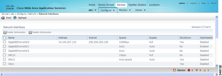
Step 2![]() Choose Configure > Network > Network Interfaces. The Network Interfaces window appears and lists the available interfaces. (See Figure 6-2.)
Choose Configure > Network > Network Interfaces. The Network Interfaces window appears and lists the available interfaces. (See Figure 6-2.)
Note![]() Loopback interfaces are not included because they are not valid interfaces for optimization. Null, Virtual-Access, NVI, and Embedded-Service interfaces are also not supported.
Loopback interfaces are not included because they are not valid interfaces for optimization. Null, Virtual-Access, NVI, and Embedded-Service interfaces are also not supported.
Figure 6-2 WAAS Express Network Interfaces Device Window
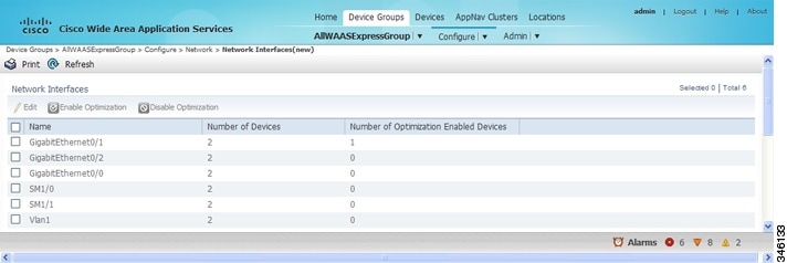
For a device group, the Network Interfaces window is different and displays an interface name, the number of devices that contain that interface, and the number of devices in the group that have optimization enabled on the interface. (See Figure 6-3.)
Figure 6-3 WAAS Express Network Interfaces Device Group Interfaces Window
Step 3![]() Check the check box next to each interface on which you want to enable WAAS optimization, and click the Enable Optimization taskbar icon; or, to disable optimization, click the Disable Optimization taskbar icon.
Check the check box next to each interface on which you want to enable WAAS optimization, and click the Enable Optimization taskbar icon; or, to disable optimization, click the Disable Optimization taskbar icon.
Note![]() Enable WAAS optimization only on WAN interfaces, not LAN interfaces.
Enable WAAS optimization only on WAN interfaces, not LAN interfaces.
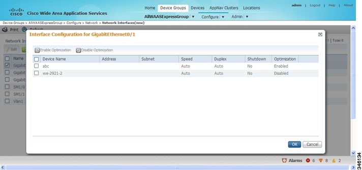
For a device group, enabling optimization for an interface enables optimization on that interface for all the devices in the group that have the interface. You can check the check box next to a single device and click the Edit taskbar icon to display a list of devices on which an interface is available and individually configure optimization on those devices. (See Figure 6-4.)
Figure 6-4 WAAS Express Network Interfaces Device Group Devices Window
Enabling WAAS Service Insertion on AppNav-XE Device Interfaces
AppNav-XE device interfaces are configured by using the router CLI, not through the WAAS Central Manager. However, you can use the Central Manager to enable or disable WAAS service insertion on the available interfaces on the router.
To enable or disable WAAS service insertion on AppNav-XE device interfaces, follow these steps:
Step 1![]() From the WAAS Central Manager menu, choose Devices > AppNav-XE-device-name.
From the WAAS Central Manager menu, choose Devices > AppNav-XE-device-name.
Step 2![]() Choose Configure > Network > Network Interfaces. The Network Interfaces window appears and lists the available interfaces.
Choose Configure > Network > Network Interfaces. The Network Interfaces window appears and lists the available interfaces.
Step 3![]() Check the check box next to an interface on which you want to enable WAAS service insertion and click the Edit taskbar icon.
Check the check box next to an interface on which you want to enable WAAS service insertion and click the Edit taskbar icon.
Step 4![]() Check the Enable WAAS Service Insertion check box; or, to disable optimization, uncheck the check box.
Check the Enable WAAS Service Insertion check box; or, to disable optimization, uncheck the check box.
Enable WAAS service insertion only on WAN interfaces, not LAN interfaces.
Step 6![]() Repeat Step 3 through Step 5 for each interface on which you want to enable WAAS service insertion.
Repeat Step 3 through Step 5 for each interface on which you want to enable WAAS service insertion.
For more information about AppNav, see Chapter4, “Configuring AppNav”
Configuring Management Interface Settings
On devices running WAAS Version 5.0 or later, you can designate a specific interface to be used as the management interface for communicating with the Central Manager, Telnet, SSH, and so on. This configuration separates management traffic from data traffic.
If you designate a management interface, you must have another active interface to handle data traffic. In addition to management interface for IPv4 traffic, a separate management interface can be configured for IPV6 traffic. This interface will use the management features with IPV6 support.
To configure the management interface settings, follow these steps:
Step 1![]() From the WAAS Central Manager menu, choose Devices > device-name.
From the WAAS Central Manager menu, choose Devices > device-name.
Step 2![]() Choose Configure > Network > Management Interface Settings.
Choose Configure > Network > Management Interface Settings.
The Management Interface Settings window appears with tabs for IPv4 and IPv6 settings. Select the appropriate one for your network before you proceed.
Step 3![]() From the Management Interface drop-down list, choose the interface that you want to use as the management interface.
From the Management Interface drop-down list, choose the interface that you want to use as the management interface.
Step 4![]() In the Management Default Gateway field, enter the default gateway IP address for management traffic.
In the Management Default Gateway field, enter the default gateway IP address for management traffic.
Step 5![]() Check the Use Management Interface for FTP Traffic check box if you want to use the designated management interface for FTP traffic.
Check the Use Management Interface for FTP Traffic check box if you want to use the designated management interface for FTP traffic.
Step 6![]() Check the Use Management Interface for TFTP Traffic check box to use the designated management interface for TFTP traffic.
Check the Use Management Interface for TFTP Traffic check box to use the designated management interface for TFTP traffic.
Step 7![]() Check the Use Management Interface for Tacacs Traffic check box to use the designated management interface for TACACS traffic.
Check the Use Management Interface for Tacacs Traffic check box to use the designated management interface for TACACS traffic.
Step 8![]() Check the Use Management Interface for Radius Traffic check box to use the designated management interface for RADIUS traffic.
Check the Use Management Interface for Radius Traffic check box to use the designated management interface for RADIUS traffic.
Step 9![]() Check the Use Management Interface for DNS Traffic check box to use the designated management interface for DNS traffic.
Check the Use Management Interface for DNS Traffic check box to use the designated management interface for DNS traffic.
Step 10![]() Check the Use Management Interface for NTP Traffic check box to use the designated management interface for NTP traffic.
Check the Use Management Interface for NTP Traffic check box to use the designated management interface for NTP traffic.
Step 11![]() Click Submit. A confirmation message appears.
Click Submit. A confirmation message appears.
To configure a different default gateway for management traffic from the CLI, use the ip default-gateway management global configuration command.
After you have designate a management interface, create static IP routes for management traffic so that an IP packet that is designated for the specified destination uses the configured route.
To configure a static route for management traffic, follow these steps:
Step 1![]() In the Management Interface Settings window, in the Management IP Routes area of this window, click the Create Management IP Route taskbar button. The Management IP Routes window appears.
In the Management Interface Settings window, in the Management IP Routes area of this window, click the Create Management IP Route taskbar button. The Management IP Routes window appears.
Step 2![]() In the Destination Network Address field, enter the destination network IP address.
In the Destination Network Address field, enter the destination network IP address.
Step 3![]() In the Netmask field, enter the destination host netmask. This field is not available when you create a IPv6 Management IP Route.
In the Netmask field, enter the destination host netmask. This field is not available when you create a IPv6 Management IP Route.
Step 4![]() In the Gateway’s IP Address field, enter the IP address of the gateway interface.
In the Gateway’s IP Address field, enter the IP address of the gateway interface.
The gateway interface IP address should be in the same network as the device’s management interface.
To configure a static route for management traffic from the CLI, use the ip route management global configuration command.
Configuring a Jumbo MTU
A jumbo MTU can be configured on the following devices: WAVE-294/594/694/7541/7571/8541, and vWAAS.
Note![]() To enable Jumbo MTU on ISR-WAAS devices, first we need to upgrade the ISR-WAAS to version 6.0 using the.ova files. The default MTU size for the virtual interface of the ISR-WAAS devices is 9000 and cannot be changed.
To enable Jumbo MTU on ISR-WAAS devices, first we need to upgrade the ISR-WAAS to version 6.0 using the.ova files. The default MTU size for the virtual interface of the ISR-WAAS devices is 9000 and cannot be changed.
If configured, a jumbo MTU applies to all the device interfaces, including logical interfaces with at least one member physical interface. The MTU for individual interfaces cannot be changed while the jumbo MTU is configured. If the jumbo MTU is disabled, all the interfaces are configured with an MTU of 1500.
To configure a jumbo MTU, follow these steps:
Step 1![]() From the WAAS Central Manager menu, choose Devices > device-name.
From the WAAS Central Manager menu, choose Devices > device-name.
Step 2![]() Choose Configure > Network > Jumbo MTU.
Choose Configure > Network > Jumbo MTU.
The Jumbo MTU Settings window appears.
Step 3![]() In the System Jumbo MTU field, enter the jumbo MTU size, in bytes, (maximum size varies by platform).
In the System Jumbo MTU field, enter the jumbo MTU size, in bytes, (maximum size varies by platform).
Note![]() If the original and optimized maximum segment sizes are set to their default values and you configure a jumbo MTU setting, the segment sizes are changed to the jumbo MTU setting minus 68 bytes. If you have configured custom maximum segment sizes, their values are not changed if you configure a jumbo MTU. For more information on configuring maximum segment sizes, see Modifying the Acceleration TCP Settings in Chapter 12, “Configuring Application Acceleration.”
If the original and optimized maximum segment sizes are set to their default values and you configure a jumbo MTU setting, the segment sizes are changed to the jumbo MTU setting minus 68 bytes. If you have configured custom maximum segment sizes, their values are not changed if you configure a jumbo MTU. For more information on configuring maximum segment sizes, see Modifying the Acceleration TCP Settings in Chapter 12, “Configuring Application Acceleration.”
To configure a jumbo MTU from the CLI, you can use the system jumbomtu global configuration command.
Configuring TCP Settings
For data transactions and queries between client and servers, the size of windows and buffers is important. Therefore, fine-tuning the TCP stack parameters becomes the key to maximizing cache performance.
Note![]() Because of the complexities involved in TCP parameters, be careful when tuning these parameters. In nearly all environments, the default TCP settings are adequate. Fine-tuning TCP settings is for network administrators with adequate experience and full understanding of TCP operation details.
Because of the complexities involved in TCP parameters, be careful when tuning these parameters. In nearly all environments, the default TCP settings are adequate. Fine-tuning TCP settings is for network administrators with adequate experience and full understanding of TCP operation details.
To configure TCP and IP settings, follow these steps:
Step 1![]() From the WAAS Central Manager menu, choose Devices > device-name ( or Device Groups > device-group-name).
From the WAAS Central Manager menu, choose Devices > device-name ( or Device Groups > device-group-name).
Step 2![]() Choose Configure > Network > TCP/IP Settings > TCP/IP. The TCP/IP Settings window appears.
Choose Configure > Network > TCP/IP Settings > TCP/IP. The TCP/IP Settings window appears.
Step 3![]() Make the necessary changes to the TCP settings.
Make the necessary changes to the TCP settings.
See Table 6-1 for a description of each TCP field in this window.
A Click Submit to Save message appears in red next to the Current Settings line when there are pending changes to be saved after you have applied default or device group settings. You can also revert to the previously configured settings by clicking Reset, which is visible only when you have applied default or group settings to change the current device settings, but have not yet submitted the changes.
|
|
|
|---|---|
Enables reduction of delay and packet loss in data transmissions. Provides TCP support for RFC 2581. By default, this option is enabled. For more information, see Explicit Congestion Notification. |
|
Initial congestion window size value, in segments. The range is 0 to 10 segments. The default is 0 segment. For more information, see Congestion Windows. |
|
Factor used to modify the length of the retransmit timer by 1 to 3 times the base value determined by the TCP algorithm. The default is 1, which leaves the times unchanged. The range is 1 to 3. For more information, see Retransmit Time Multiplier. Note Modify this factor with caution. It can improve throughput when TCP is used over slow reliable connections, but should never be changed in an unreliable packet delivery environment. |
|
Number of times that the WAAS device can retry a connection before the connection is considered unsuccessful. The range is 1 to 120 attempts. The default is 4 attempts. |
|
Length of time that the WAAS device keeps an idle connection open. The default is 75 seconds. |
|
Length of time that the WAAS device keeps a connection open before disconnecting. The range is 1 to 120 seconds. The default is 90 seconds. |
|
Enables discovery of the largest IP packet size allowable between the various links along the forwarding path and automatically sets the correct value for the packet size. By default, this option is disabled. For more information, see Path MTU Discovery. |
|
To configure TCP settings from the CLI, use the tcp global configuration command.
To enable the MTU discovery utility from the CLI, use the ip path-mtu-discovery enable global configuration command.
This section contains the following topics:
- Explicit Congestion Notification
- Congestion Windows
- Retransmit Time Multiplier
- TCP Slow Start
- Path MTU Discovery
Explicit Congestion Notification
The TCP Explicit Congestion Notification (ECN) feature allows an intermediate router to notify the end hosts of impending network congestion. It also provides enhanced support for TCP sessions associated with applications that are sensitive to delay or packet loss. The major issue with ECN is that the operation of both the routers and the TCP software stacks needs to be changed to accommodate the operation of ECN.
Congestion Windows
The congestion window ( cwnd) is a TCP state variable that limits the amount of data that a TCP sender can transmit to the network before receiving an acknowledgment (ACK) from the receiving side of the TCP transmission. The TCP cwnd variable is implemented by the TCP congestion avoidance algorithm. The goal of the congestion avoidance algorithm is to continually modify the sending rate so that the sender automatically senses any increase or decrease in available network capacity during the entire data flow. When congestion occurs (manifested as packet loss), the sending rate is first lowered, and then gradually increased as the sender continues to probe the network for additional capacity.
Retransmit Time Multiplier
A TCP sender uses a timer to measure the time that has elapsed between sending a data segment and receiving the corresponding ACK from the receiving side of the TCP transmission. When this retransmit timer expires, the sender (according to the RFC standards for TCP congestion control) must reduce its sending rate. However, because the sender is not reducing its sending rate in response to network congestion, the sender is not able to make any valid assumptions about the current state of the network. Therefore, in order to avoid congesting the network with an inappropriately large burst of data, the sender implements the slow start algorithm, which reduces the sending rate to one segment per transmission. (See TCP Slow Start.)
You can modify the sender’s retransmit timer by using the Retransmit Time Multiplier field in the WAAS Central Manager. The retransmit time multiplier modifies the length of the retransmit timer by one to three times the base value, as determined by the TCP algorithm that is being used for congestion control.
Note![]() When making adjustments to the retransmit timer, be aware that they affect performance and efficiency. If the retransmit timer is triggered too early, the sender pushes duplicate data onto the network unnecessarily; if the timer is triggered too slowly, the sender remains idle for too long, unnecessarily slowing data flow.
When making adjustments to the retransmit timer, be aware that they affect performance and efficiency. If the retransmit timer is triggered too early, the sender pushes duplicate data onto the network unnecessarily; if the timer is triggered too slowly, the sender remains idle for too long, unnecessarily slowing data flow.
TCP Slow Start
Slow start is one of four congestion-control algorithms used by TCP. The slow-start algorithm controls the amount of data being inserted into the network at the beginning of a TCP session when the capacity of the network is not known.
For example, if a TCP session began with an insertion of a large amount of data into the network, much of the initial burst of data is likely be lost. Instead, TCP should initially transmit a modest amount of data, which has a high probability of successful transmission. Next, TCP can probe the network by sending increasing amounts of data as long as the network does not show signs of congestion.
The slow-start algorithm begins by sending packets at a rate that is determined by the congestion window, or cwnd variable. (See Congestion Windows.) The algorithm continues to increase the sending rate until it reaches the limit set by the slow-start threshold ( ssthresh) variable. Initially, the value of the ssthresh variable is adjusted to the receiver’s maximum segment size (RMSS). However, when congestion occurs, the ssthresh variable is set to half the current value of the cwnd variable, marking the point of the onset of network congestion for future reference.
The starting value of the cwnd variable is set to that of the sender maximum segment size (SMSS), which is the size of the largest segment that a sender can transmit. The sender sends a single data segment, and because the congestion window is equal to the size of one segment, the congestion window is full. The sender then waits for the corresponding ACK from the receiving side of the transmission. When the ACK is received, the sender increases the congestion window size by increasing the value of the cwnd variable by the value of one SMSS. Now the sender can transmit two segments before the congestion window is again full and the sender is once more required to wait for the corresponding ACKs for these segments. The slow-start algorithm continues to increase the value of the cwnd variable, and thus increases the size of the congestion window by one SMSS for every ACK received. If the value of the cwnd variable increases beyond the value of the ssthresh variable, the TCP flow-control algorithm changes from the slow-start algorithm to the congestion-avoidance algorithm.
Path MTU Discovery
The WAAS software supports the IP Path Maximum Transmission Unit (MTU) Discovery method, as defined in RFC 1191. When enabled, the Path MTU Discovery feature discovers the largest IP packet size allowable between the various links along the forwarding path and automatically sets the correct value for the packet size. By using the largest MTU that the links can handle, the sending device can minimize the number of packets it must send.
IP Path MTU Discovery is useful when a link in a network goes down, which forces the use of another, different MTU-sized link. IP Path MTU Discovery is also useful when a connection is first being established, and the sender has no information about the intervening links.
Note![]() IP Path MTU Discovery is a process initiated by the sending device. If a server does not support IP Path MTU Discovery, the receiving device will have no available means to avoid fragmenting datagrams generated by the server.
IP Path MTU Discovery is a process initiated by the sending device. If a server does not support IP Path MTU Discovery, the receiving device will have no available means to avoid fragmenting datagrams generated by the server.
By default, this feature is disabled. With the feature disabled, the sending device uses a packet size that is the lesser of 576 bytes and the next hop MTU. Existing connections are not affected when this feature is turned on or off.
Configuring a Static IP Route
The WAAS software allows you to configure a static route for a network or host. Any IP packet designated for the specified destination uses the configured route.
To configure a static IP route, follow these steps:
Step 1![]() From the WAAS Central Manager menu, choose Devices > device-name ( or Device Groups > device-group-name).
From the WAAS Central Manager menu, choose Devices > device-name ( or Device Groups > device-group-name).
Step 2![]() Choose Configure > Network > TCP/IP Settings > Static Routes. The IP Route Entries window appears.
Choose Configure > Network > TCP/IP Settings > Static Routes. The IP Route Entries window appears.
Step 3![]() In the taskbar, click the Create New IP Route Entry icon. The Creating New IP Route window appears.
In the taskbar, click the Create New IP Route Entry icon. The Creating New IP Route window appears.
Step 4![]() In the Destination Network Address field, enter the destination network IP address.
In the Destination Network Address field, enter the destination network IP address.
Step 5![]() In the Netmask field, enter the destination host netmask.
In the Netmask field, enter the destination host netmask.
Step 6![]() In the Gateway’s IP Address field, enter the IP address of the gateway interface.
In the Gateway’s IP Address field, enter the IP address of the gateway interface.
The gateway interface IP address should be in the same network as that of one of the device’s network interfaces.
Step 7![]() Alternately, if you select the check box for IPv6 Address, you need to specify the details only for the Destination Network Address and the Gateway’s IP Address field.
Alternately, if you select the check box for IPv6 Address, you need to specify the details only for the Destination Network Address and the Gateway’s IP Address field.
To configure a static route from the CLI, use the ip route global configuration command.or IPv6 route global configuration command.
Aggregating IP Routes
An individual WAE device can have IP routes defined and can belong to device groups that have other IP routes defined.
In the IP Route Entries window, the Aggregate Settings radio button controls how IP routes are aggregated for an individual device, as follows:
- Choose Yes to configure the device with all the IP routes that are defined for itself and for the device groups to which it belongs.
- Choose No to limit the device to just the IP routes that are defined for itself.
When you change the setting, you get the following confirmation message: This option will take effect immediately and will affect the device configuration. Do you wish to continue? Click OK to continue.
Configuring CDP Settings
The Cisco Discovery Protocol (CDP) is a device discovery protocol that runs on all Cisco-manufactured devices. With CDP, each device in a network sends periodic messages to all the other devices in the network. All the devices listen to periodic messages that are sent by others to learn about neighboring devices and determine the status of their interfaces.
With CDP, network management applications can learn the device type and the Simple Network Management Protocol (SNMP) agent address of neighboring devices. Applications are able to send SNMP queries within the network. CiscoWorks2000 also discovers the WAAS devices by using the CDP packets that are sent by the WAAS device after booting.
To perform device-related tasks, the WAAS device platform must support CDP to be able to notify the system manager of the existence, type, and version of the WAAS device platform.
To configure CDP settings, follow these steps:
Step 1![]() From the WAAS Central Manager menu, choose Devices > device-name ( or Device Groups > device-group-name).
From the WAAS Central Manager menu, choose Devices > device-name ( or Device Groups > device-group-name).
Step 2![]() Choose Configure > Network > CDP. The CDP Settings window appears.
Choose Configure > Network > CDP. The CDP Settings window appears.
Step 3![]() Check the Enable check box to enable CDP support. By default, this option is enabled.
Check the Enable check box to enable CDP support. By default, this option is enabled.
Step 4![]() In the Hold Time field, enter the time (in seconds) to specify the length of time that a receiver is to keep the CDP packets.
In the Hold Time field, enter the time (in seconds) to specify the length of time that a receiver is to keep the CDP packets.
The range is 10 to 255 seconds. The default is 180 seconds.
Step 5![]() In the Packet Send Rate field, enter a value (in seconds) for the interval between CDP advertisements.
In the Packet Send Rate field, enter a value (in seconds) for the interval between CDP advertisements.
The range is 5 to 254 seconds. The default is 60 seconds.
To configure CDP settings from the CLI, use the cdp global configuration command.
Configuring the DNS Server
DNS allows the network to translate the domain names entered in requests into their associated IP addresses. To configure DNS on a WAAS device, you must complete the following tasks:
- Specify the list of DNS servers that are used by the network to translate requested domain names into IP addresses (both IPv4 and IPv6) that the WAAS device should use for domain name resolution.
- Enable DNS on the WAAS device.
To configure DNS server settings for a WAAS device, follow these steps:
Step 1![]() From the WAAS Central Manager menu, choose Devices > device-name ( or Device Groups > device-group-name).
From the WAAS Central Manager menu, choose Devices > device-name ( or Device Groups > device-group-name).
Step 2![]() Choose Configure > Network > DNS. The DNS Settings window appears.
Choose Configure > Network > DNS. The DNS Settings window appears.
Step 3![]() In the Local Domain Name field, enter the name of the local domain. You can configure up to three local domain names. Separate items in the list with a space.
In the Local Domain Name field, enter the name of the local domain. You can configure up to three local domain names. Separate items in the list with a space.
Step 4![]() In the List of DNS Servers field, enter a list of DNS servers used by the network to resolve hostnames to IP addresses.
In the List of DNS Servers field, enter a list of DNS servers used by the network to resolve hostnames to IP addresses.
You can configure up to three DNS servers. Separate items in the list with a space.
A Click Submit to Save message appears in red next to the Current Settings line when there are pending changes to be saved after you have applied default and device group settings. To revert to the previously configured window settings, click Reset, which appears only when you have applied default or group settings to change the current device settings, but the settings have not yet been submitted.
To configure DNS name servers from the CLI, use the ip name-server global configuration command.
Note![]() On ISR-WAAS devices you cannot configure the DNS server from the Central Manager.
On ISR-WAAS devices you cannot configure the DNS server from the Central Manager.
Configuring Windows Name Services
To configure Windows name services for a device or device group, follow these steps:
Step 1![]() From the WAAS Central Manager menu, choose Devices > device-name ( or Device Groups > device-group-name).
From the WAAS Central Manager menu, choose Devices > device-name ( or Device Groups > device-group-name).
Step 2![]() Choose Configure > Network > WINS. The Windows Name Services Settings window appears.
Choose Configure > Network > WINS. The Windows Name Services Settings window appears.
Step 3![]() In the Workgroup or Domain Name field, enter the name of the workgroup (or domain) in which the chosen device or device group resides.
In the Workgroup or Domain Name field, enter the name of the workgroup (or domain) in which the chosen device or device group resides.
This name must be entered in shortname format and cannot exceed 15 characters. Valid characters include alphanumeric characters, a forward slash (\), an underscore (_), and a dash (-).
For example, if your domain name is cisco.com, the short name format is cisco.
Step 4![]() Check the NT check box if the workgroup or domain is a Windows NT 4 domain. For example, if your domain name is cisco.com, the short name format is cisco. If your workgroup or domain is a Windows 2000 or Windows 2003 domain, do not check the NT check box. By default, this option is disabled.
Check the NT check box if the workgroup or domain is a Windows NT 4 domain. For example, if your domain name is cisco.com, the short name format is cisco. If your workgroup or domain is a Windows 2000 or Windows 2003 domain, do not check the NT check box. By default, this option is disabled.
Step 5![]() In the WINS Server field, enter the hostname or IP address of the Windows Internet Naming Service (WINS) server.
In the WINS Server field, enter the hostname or IP address of the Windows Internet Naming Service (WINS) server.
To configure Windows name services from the CLI, use the windows-domain global configuration command.
 Feedback