- About This Guide
- Overview of Content Support in Cisco Vision Dynamic Signage Director
- Overview of Content Deployment in Cisco Vision Dynamic Signage Director
- Video Wall Planning in Cisco Vision Dynamic Signage Director
- Screen Template Specifications for Cisco Vision Dynamic Signage Director
- Content Guidelines and Specifications for Cisco Vision Dynamic Signage Director
- HTML Content Creation Guidelines for Cisco Vision Dynamic Signage Director
Overview of Content Deployment in Cisco Vision Dynamic Signage Director
Before you begin to deploy content at your venue, it is important that you understand all of the requirements for the types and methods of content that you want to deploy.
There are limitations and specifications for the content size and formats supported by Cisco Vision Dynamic Signage Director. These vary depending upon a number of factors including the TV display resolution, the media player used in the venue, the screen template region layout, and the TV proximity to the fans.
Note: For a full range of content planning and design services available from Cisco Systems, contact the Cisco Creative Services team.
Workflow Summary for Content Deployment
Table 1 gives an example of what a workflow plan might look like.
Overview of Content Support in Cisco Vision Dynamic Signage Director. |
|
Content Guidelines and Specifications for Cisco Vision Dynamic Signage Director. |
|
Plan and create the screen template and region sizes for your content. |
Screen Template Specifications for Cisco Vision Dynamic Signage Director. |
Create your content and get it into Cisco Vision Dynamic Signage Director. |
Overview of Content Support in Cisco Vision Dynamic Signage Director. |
Create a script to define when your content is displayed (as needed). |
Overview of Configuration Objects for Content Deployment
Table 2 provides a simple description of the different configuration objects in Cisco Vision Dynamic Signage Director that are used for content deployment.
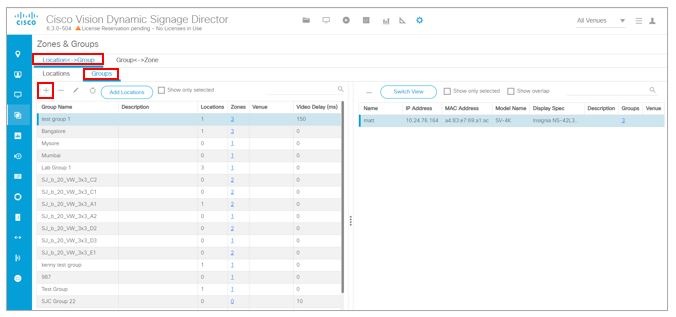
Zones, Groups, and Locations
Digital content, in the form of still or animated graphics and video ad insertions, can be targeted and delivered—with accompanying event video—to any display or group of displays throughout the venue.
When you have hundreds or thousands of TVs on which you want to display different video signage, sponsored content, TV channels, and menus, you need a way to automate the configuration and manage the endpoint locations.
Cisco Vision Dynamic Signage Director defines a hierarchical architecture of Groups, Zones, and Locations that allows you to easily identify the location of the displays and manage the content that they are playing.
Zones
A zone is typically a physical area in the venue. Concourses, clubs, and team stores are examples. Groups and zones allow you to apply attributes to a number of screens with a single action. They simplify the control of advertisements in sponsored areas of the venue, enabling all the screens in a sponsored zone to have the same branded messages, the same playlists, and the same video content.
Group and zone associations can be made any time prior to pushing an event script and can be used for multiple events.
Groups
A group defines a collection of devices (DMPs/TVs) that all display the same content, using the same template. Groups are the second level in the hierarchy and are subsets of a zone. Groups contain a set of locations in the hierarchy.
To understand the use of groups, consider the TVs in a concourse area on which you want to show a game feed with sponsored advertising. Rather than configure each individual TV to show this content, you can configure them as a group and change all of the TVs with a single action. The group is associated to a zone to identify the area of the venue where the TVs are located.
Locations
Locations are the lowest level in the hierarchy. A location is a subset of a group that defines a specific place in the venue where a TV and DMP reside. After DMPs are deployed, they must be linked to Locations to change their state to “Ready” so that you can stage content to the DMP.
Locations help you keep track of exactly where a TV and DMP is physically located in the venue. For example, if someone tells you that a TV in a restroom at the concourse 100 level is not working, you can refer to the location information to quickly find the TV and fix it.
Note: Be careful not to confuse the civic location on Cisco Catalyst switches with the DMP Location in Cisco Vision Dynamic Signage Director.
Figure 1 shows an example of a nested hierarchy, with naming conventions that help describe the area and use of a group of devices.
Figure 1 Zone, Group, and Location Example
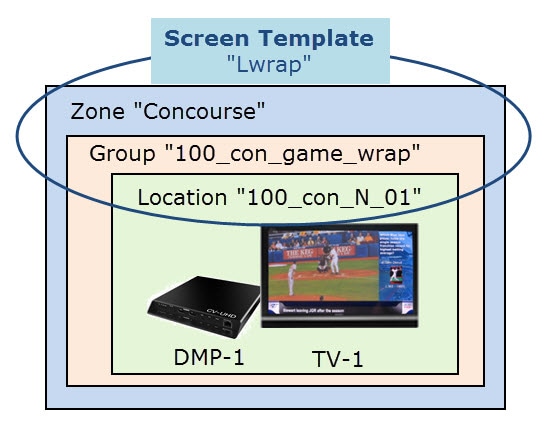
In Figure 1, a zone named “Concourse” is at the top level, with a group named “100_con_game_wrap” that is part of the “Concourse” zone. As indicated by the name of the group, this is for all of the TV displays using the game wrap format (from a screen template) in Concourse 100 of the venue. A location named “100_con_N_01” indicates that the TV-1 and DMP-1 are located on the North Concourse 100 level.
Best Practices for Groups and Zones
■![]() The more groups and zones you have, the more complicated the deployment becomes. Plan carefully.
The more groups and zones you have, the more complicated the deployment becomes. Plan carefully.
■![]() Logically group unique advertising areas, concessions, and exit directions to reduce operational complexity.
Logically group unique advertising areas, concessions, and exit directions to reduce operational complexity.
■![]() While it is possible for a zone to have different screen templates throughout the course of an event, the more screen templates you use, the more complex the deployment and administration becomes. To simplify the system management, limit the number of screen templates for a given zone.
While it is possible for a zone to have different screen templates throughout the course of an event, the more screen templates you use, the more complex the deployment and administration becomes. To simplify the system management, limit the number of screen templates for a given zone.
For more information about guidelines for zones and groups, see the Cisco Vision Dynamic Signage Operations Guide, Release 6.2.
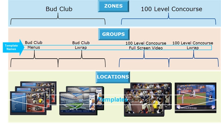
Templates
Templates are not technically part of the device hierarchy. However, screen templates are an important concept to understand within the group-zone hierarchy because they are assigned to groups and zones to define the format of the TV displays within them. Screen templates define how a particular TV display is divided into regions to show different arrangements of video, signage, and advertising.
Note: Every device belonging to the same group will display the same template as shown in Figure 2.
Figure 1 shows that a screen template named “Lwrap” is associated with the TV display in location “100_con_N_01,” which is part of the “100_con_grame_wrap” device group. This example shows only one location, but if there were many locations within the group, the same template would apply to all of those TV displays.
Figure 2 Zones, Groups, and Locations and Screen Template Association
Playlists
For most content to appear, it has to be put into a playlist. A playlist is a series of content items (static images, video, widgets, external URLs) that are grouped together to display in sequential order (one after the other) for a set duration and repeat. The playlist is associated with and appears in a given area of the screen called a region. Regions are defined by the screen template.
Each playlist runs independently of other playlists and multiple playlists can be run in any given event script in separate regions.
Playlists are defined by the type of content that they contain—either static images only (Non Video), or video/other content types (Video or Mixed Media). A playlist that is configured as “Video or Mixed Media” can contain both video and static images, as well as other content types.
One of the most common uses of a playlist is in a screen template region where a series of advertisements cycle based upon a preset rotation. Playlists also can include tickers and full screen messages, among a number of other types of content.
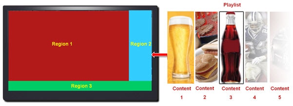
Figure 3 shows an example of a playlist that contains five static images that will each display for a set duration in Region 2 of the screen template.
Figure 3 Playlist Example of Static Images for Display in Template Region 2
Note: Playlists become part of an event script. Stage, or pre-load, event scripts to the DMPs prior to the event from the Script Management screen.
Scripts
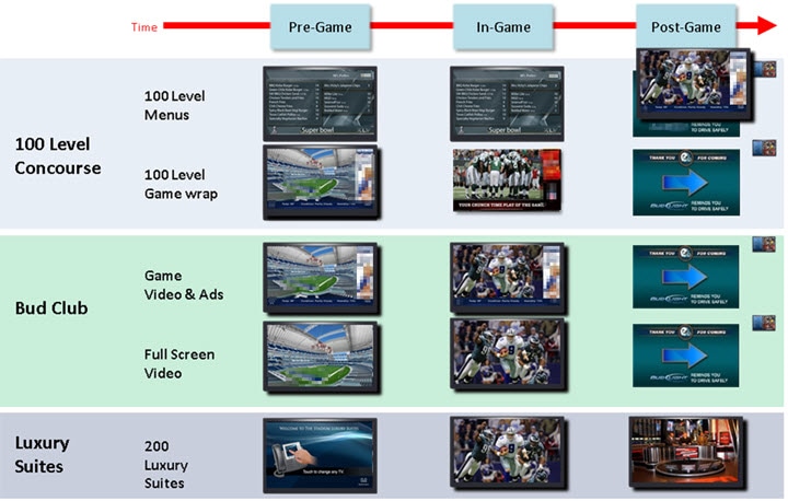
Event scripts and event states control when certain content displays on the TV screens in a venue over the course of an event (Figure 4).
You create event scripts and event states ahead of an event, allowing you to predetermine what will display at a given time and location on each screen in the venue. Prior to the event, stage and validate the script. Make necessary adjustments so everything displays correctly.
Run the script at the scheduled event time. Initiate the script manually or automatically. Once the script is running, use the many features of Cisco Vision Dynamic Signage Director to further manage the ads, content, graphics, and video displayed throughout the course of the event.
Figure 5 shows an example of the progression of a script through different stages of the event. At each change in the event state (Pre-Game, In-Game, Post-Game) the screen template and content applied to the TV displays changes within the group and/or zone.
Figure 5 Example of the Progression of an Event Script
Channel Content Deployment
This section includes the following topics:
■![]() Content Deployed From Local HDMI-In (HDMI-In Pass-Through)
Content Deployed From Local HDMI-In (HDMI-In Pass-Through)
Overview of Channel Sources
Table 3 provides a list of the types of content that can be used as channel sources in Cisco Vision Dynamic Signage Director Release 6.3. It also summarizes where you can control that content as a channel source.
|
Type |
Video |
Across DMPs |
|
|
||||
|
|
|
|
|
API |
||||
|
|
|
|
|
|
|
|
|
|
|
|
|
|
|
|
|
|
|
|
|
|
|
|
|
|
|
|
|
|
|
|
|
|
|
|
|
|
|
|
|
|
|
|
|
|
|
|
|
|
Note: Channel sources on second video region will not play audio, in general.
Note: Use only external URLs that can be embedded in an I-frame. To test the X-Frame option in the external content, see Detect X-Frame-Options in External URLs.
DMP-Created Channel Sources
Table 4 provides a list of DMP-created channel sources in Cisco Vision Dynamic Signage Director Release 6.3.
Content Deployed From Local HDMI-In (HDMI-In Pass-Through)
Note: Local HDMI-In content is supported by the SV-4K, CV-UHD, and CV-UHD2 DMPs only.
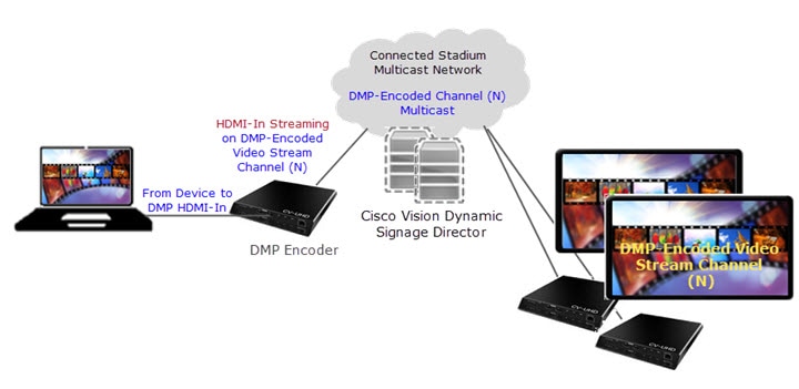
Local HDMI-In support is simplified, where DMP encoding of the local HDMI-In port is automatically set up in the system as a default channel (Channel 0). This means that all you have to do is plug an HDCP-compliant device into the HDMI-In port on an SV-4K, CV-UHD, or CV-UHD2 digital media player and it automatically plays content on Channel 0 in Cisco Vision Dynamic Signage Director (Figure 6). You can tune to the channel from a script, User Control API, IP phone, or IR remote.
Use the local HDMI-In channel when you want to easily send local content to a single TV display using the HDMI-In port of the DMP on an SV-4K, CV-UHD, or CV-UHD2 DMP. The primary use case for HDMI-In pass-through is for sharing of presentations or external video source that you want to display on the one TV to which the source is connected.
Figure 6 Local HDMI-In Pass-Through to Single TV Display
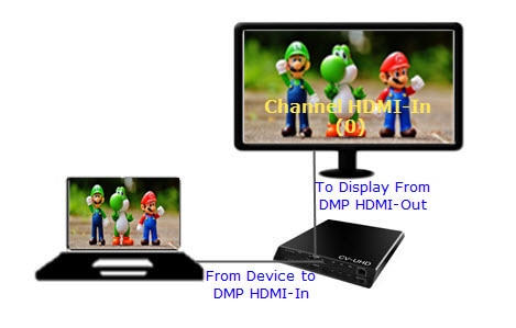
When you are playing content through the DMP HDMI-In port, the content is “always on” on Channel 0, much like any other streamed channel on a TV. To stop playing the content, stop it on the source device connected to the DMP or tune to a different channel in Cisco Vision Dynamic Signage Director. If you are tuning to the channel by script, change states or stop the script.
Streaming Options for Local HDMI-In to Multiple DMPs
The local HDMI-In channel is intended for a single-content source to be shown on a single TV display.
To distribute the local HDMI-In content to multiple DMPs in the system, use one of two streaming methods summarized in Table 5. Both streaming methods require configuration of a DMP-encoded video stream channel to which the encoded video is sent and where other DMPs can be tuned. See also Video Streaming Methods.S
|
|
Support |
|
|
|
(Encoding of HDMI-In source only) |
|
■ |
|
|
|
|
|
2.Controlling starting and stopping of streaming from the Device Management is intended for testing only. |
Video Streaming Methods
Display Streaming
Display streaming renders a full-screen display (including multiple template regions) as a multicast stream without audio. You can control display streaming by the new Start Display Streaming / Stop Display Streaming script state actions, from the User Control API, or the Script Management interface.
Note: Display Streaming supports video only (no audio). However, if you want to stream DMP-encoded HDMI-In channel content only, then both audio and video are available. If you use HDMI-In Streaming rather than Display Streaming as a script state action applied on the designated video stream channel.
Use a DMP-encoded video stream channel with display streaming to do the following with your content:
■![]() Broadcast full-screen output from a DMP display to multiple other DMPs in the system.
Broadcast full-screen output from a DMP display to multiple other DMPs in the system.
■![]() Support DMP-to-DMP synchronization (non-video wall).
Support DMP-to-DMP synchronization (non-video wall).
■![]() Display video only (without audio).
Display video only (without audio).
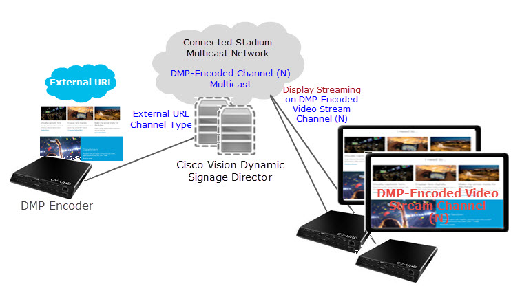
Figure 7 shows an example of an HTML page configured in the system as an External URL channel and streamed to a DMP-encoded Video Stream multicast channel using display streaming.
Note: Use only external URLs that do not set the X-Frame Options header. To test the X-Frame option in the external content, see Detect X-Frame-Options in External URLs.
Figure 7 External URL Example with Display Streaming to a DMP-Encoded Multicast Channel
1.![]() Configure an External URL channel with the URL of the content that you want to stream.
Configure an External URL channel with the URL of the content that you want to stream.
Note: The system will determine an HTTP Live Stream (HLS) based on the file extension in the URL.
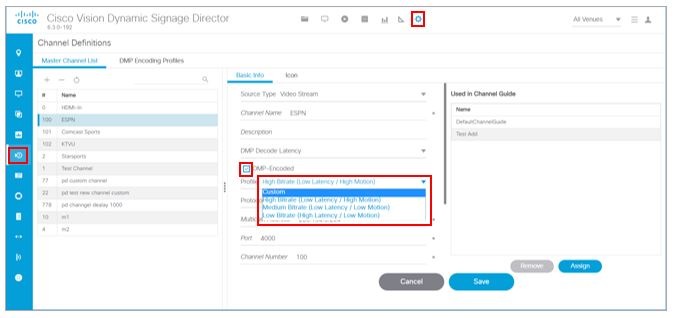
2.![]() Configure a Video Stream channel with DMP encoding enabled (Figure 8).
Configure a Video Stream channel with DMP encoding enabled (Figure 8).
Figure 8 Enabling DMP Encoding
3.![]() Create a group containing only the DMP to be used for the encoding of the URL (Figure 9).
Create a group containing only the DMP to be used for the encoding of the URL (Figure 9).
4.![]() Create a script and select a video template as an action for the DMP Group in Step 3..
Create a script and select a video template as an action for the DMP Group in Step 3..
5.![]() Assign the External URL channel to the video region.
Assign the External URL channel to the video region.
6.![]() Select the Start Display Streaming action and choose the DMP encoded channel that you set up.
Select the Start Display Streaming action and choose the DMP encoded channel that you set up.
HDMI-In Streaming
Note: Local HDMI-In content is supported by the SV-4K, CV-UHD, and CV-UHD2 DMPs only.
When combined with use of a DMP-encoded video stream channel, you also can choose to broadcast a local HDMI-In channel to a DMP-encoded channel for availability of the content to other DMPs in the system.
Note: HDMI-In streaming is only supported for content sourced by the HDMI-In port on the SV-4K, CV-UHD, and CV-UHD2.
Figure 10 shows an example of streaming content to a DMP-encoded video stream channel from a device connected to the DMP HDMI-In port.
Figure 10 HDMI-In Streaming Example from Single DMP to Multiple DMPs
1.![]() Connect an HDCP-compliant content source to the HDMI-In port on the DMP (the encoding DMP).
Connect an HDCP-compliant content source to the HDMI-In port on the DMP (the encoding DMP).
Note: Because the HDMI-In port has an internal, universal identifier representing the local HDMI-In of the device, the encoding DMP must be in its own Group in Cisco Vision Dynamic Signage Director.
2.![]() Configure the destination Video Stream channel where the HDMI-In content will be streamed ( never Channel 0). This must be a DMP-encoded video stream channel.
Configure the destination Video Stream channel where the HDMI-In content will be streamed ( never Channel 0). This must be a DMP-encoded video stream channel.
3.![]() Create a group containing only the DMP to be used for the encoding of the URL.
Create a group containing only the DMP to be used for the encoding of the URL.
4.![]() Create a script and select a video template as an action for the DMP Group in Step 3..
Create a script and select a video template as an action for the DMP Group in Step 3..
5.![]() Select the Start HDMI-In Streaming (encoding) action and choose the DMP-encoded video channel that you set up in 2..
Select the Start HDMI-In Streaming (encoding) action and choose the DMP-encoded video channel that you set up in 2..
6.![]() To receive (decode) the stream on other DMPs in the system, tune to the DMP-encoded channel.
To receive (decode) the stream on other DMPs in the system, tune to the DMP-encoded channel.
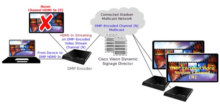
Restrictions for HDMI-In Streaming
The HDMI-In port on the digital media player can only be supported either as a source to video region or source to encoder as a channel, but not both.
Therefore, if you want to connect a TV display to the DMP encoder’s HDMI-Out port, while also doing HDMI-In streaming from that DMP, you cannot tune that TV to Channel HDMI-In (Figure 11).
Figure 11 Unsupported DMP Encoder Configuration for HDMI-In Streaming
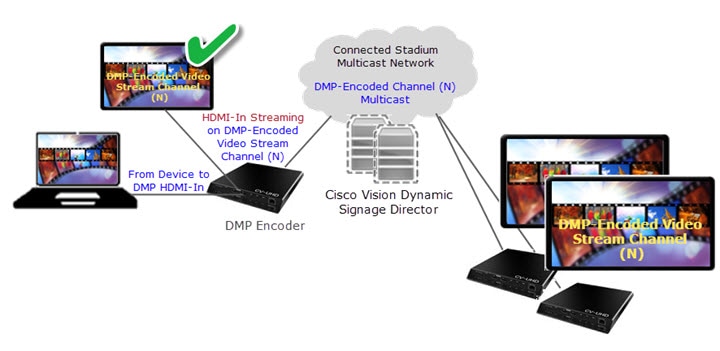
You can connect a TV display to that DMP encoder, as long as it is tuned to the DMP-encoded video stream channel and not Channel HDMI-In (Figure 12).
Figure 12 Supported DMP Encoder Configuration with TV Display for HDMI-In Streaming
Note : For HDMI-In streaming, the maximum resolution you can use is full HD (1920 X 1080 X 60p) for the input port to HDMI-In. Otherwise, your HDMI-In may not produce the desired result (clear, full screen).
Unicast Streaming
Note: Multicast state change deployments are the recommended best practice.
Unicast streaming cover cases where Cisco Vision Director cannot reach a DMP via multicast. Use unicast streaming in situations where there may be DMPs outside the main venue, or located and configured in such a way that you cannot use multicast routing. Unicast state change DMPs do not have the full feature set that multicast offers.
The following are some limitations with unicast state change messages:
■![]() DMPs using unicast state change messages will not synchronize state changes, either with other unicast state change DMPs, or with DMPs using multicast state change messages. This lack of screen to screen synchronization may affect all content types.
DMPs using unicast state change messages will not synchronize state changes, either with other unicast state change DMPs, or with DMPs using multicast state change messages. This lack of screen to screen synchronization may affect all content types.
■![]() Unicast state change messages do not solve any other required use of multicast in the system, including the following:
Unicast state change messages do not solve any other required use of multicast in the system, including the following:
–![]() Zone-based video wall synchronization communication between DMPs relies on multicast communication between the DMPs within a video wall.
Zone-based video wall synchronization communication between DMPs relies on multicast communication between the DMPs within a video wall.
–![]() PTP use of multicast communication
PTP use of multicast communication
–![]() Multicast updates of external data sources through the data integration feature, in combination with a widget. As a workaround, configure a data binding component within widgets that use the data integration feature.
Multicast updates of external data sources through the data integration feature, in combination with a widget. As a workaround, configure a data binding component within widgets that use the data integration feature.
To set up unicasting to a DMP:
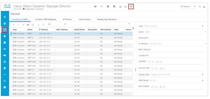
1.![]() Click Configuration > Devices > Locations & DMPs tab (Figure 13).
Click Configuration > Devices > Locations & DMPs tab (Figure 13).
Figure 13 Choose the Device to Unicast
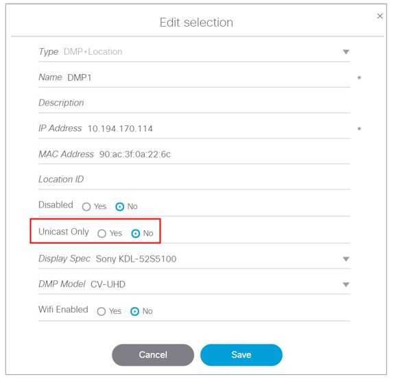
2.![]() Select a specific device from your list and click the Edit icon. The Edit selection dialog box appears (Figure 14).
Select a specific device from your list and click the Edit icon. The Edit selection dialog box appears (Figure 14).
Figure 14 Selecting Unicast Option for a Specific DMP
State Delay—A Workaround
DMPs using unicast state change messages will not synchronize their state changes with other DMPs, either those using unicast state change DMPs, or with DMPs using multicast state changes.
One possible workaround is for the system to delay the implementation of state changes, to try to allow the system to communicate to all unicast DMPs.
Note: This procedure is intended solely as a workaround for those experiencing synchronization issues due to unicast state change messages. Do not enable state delay unless you specifically experience such synchronization issues. Be aware of the caveats as listed above.
To set the unicast registry in DSD for the device:
1.![]() Click Configuration > System Configuration > Advanced Registry Settings.
Click Configuration > System Configuration > Advanced Registry Settings.
2.![]() Click Add (+) (Figure 15). The Create Configuration Setting dialog box appears.
Click Add (+) (Figure 15). The Create Configuration Setting dialog box appears.
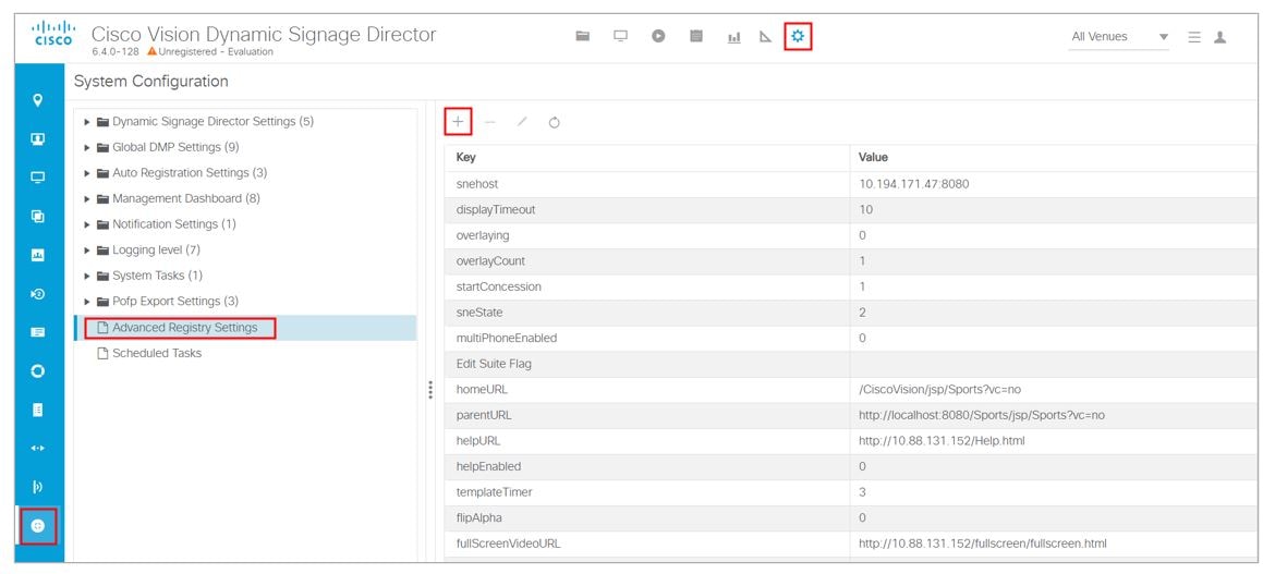
3.![]() In the Name field, type script.stateChange.nextStateDelay.
In the Name field, type script.stateChange.nextStateDelay.
4.![]() In the Value field, type n, where n is the number of seconds to delay state changes by.
In the Value field, type n, where n is the number of seconds to delay state changes by.
State Delay Caveats
■![]() State delay effects all DMPs in the system: DMPs using unicast and DMPs using multicast state change messages.
State delay effects all DMPs in the system: DMPs using unicast and DMPs using multicast state change messages.
■![]() State delay will cause all state changes to be delayed by that time, making it more difficult to make quick changes to the state.
State delay will cause all state changes to be delayed by that time, making it more difficult to make quick changes to the state.
■![]() State delay is “best effort.” There is no guarantee that the value chosen above will achieve synchronization of state change messages, given the network and system conditions.
State delay is “best effort.” There is no guarantee that the value chosen above will achieve synchronization of state change messages, given the network and system conditions.
Do not make state changes while the state change is pending; unpredictable results may occur.
 Feedback