Introduction
This document describes how to configure a 9800 Wireless LAN Controller (WLC) to connect Virtual Machine (VM) Bridge Client.
Prerequisites
Requirements
Cisco recommends that you have basic knowledge of these topics:
- Cisco 9800 Series Wireless LAN Controller (WLC) configuration concepts
- Cisco Wave 2 Access Point (AP) configuration concepts
- Cisco Access Point registration and mode configuration concepts
- VirtualBox networking and virtual machine setup concepts
Components Used
The information in this document is based on these software and hardware versions:
- 9800-CL WLC with Cisco IOS® 17.15.3
- Control And Provisioning of Wireless Access Points (CAPWAP) APs model CW9176I
- VM with VirtualBox version 7.1.10
- Operating System Ubuntu version 24.04.2 Long-Term Support (LTS)
- Wireless client laptops with Windows 11 Home
The information in this document was created from the devices in a specific lab environment. All of the devices used in this document started with a cleared (default) configuration. If your network is live, ensure that you understand the potential impact of any command
Background Information
VM utilizes the physical Wi-Fi adapter of the host laptop to establish network connectivity, ensuring seamless integration with the existing network infrastructure. The DHCP server assigns a unique IP address to the VM, enabling proper identification and communication within the network.
While the VM utilizes the host laptop physical Wi-Fi adapter, it does not directly manage the wireless connection. Instead, the host laptop acts as a bridge, managing the Wi-Fi connection and providing network access to the VM. Consequently, the VM cannot view or control Wi-Fi networks directly, as this functionality is handled by the host system. This configuration ensures that the VM maintains a robust presence on the network while efficiently utilizing the host physical resources.
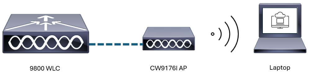
Network Diagram
The network diagram features a Cisco Catalyst 9800 Wireless LAN Controller (WLC) and CW9176I Access Points (APs) that provide wireless connectivity to devices such as a laptop and a virtual machine (VM) hosted on VirtualBox. The 9800 WLC acts as the central management and control unit, ensuring seamless integration and efficient operation of the wireless network. The CW9176I APs, equipped with advanced Wi-Fi 7 capabilities, enable high-speed and reliable wireless communication for connected devices. The Host VM laptop runs Windows 11 Home and operates a VirtualBox VM with Ubuntu software.
 Network Diagram
Configurations
VLAN Configurations
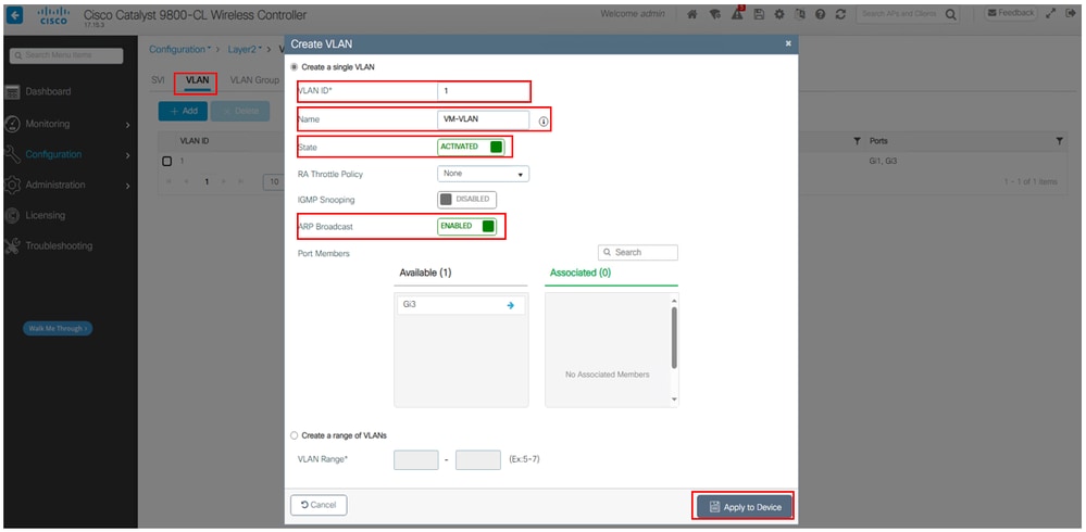
The ARP broadcast feature on the Cisco Catalyst 9800 Wireless Controller is essential for enabling communication in networks with passive clients. This feature broadcasts ARP requests across all devices within a VLAN, which is particularly beneficial for passive clients like Virtual Machines in Bridged Adapter mode that do not actively send their IP information.
WLC GUI
Navigate to Configurations > Layer2 > VLAN > Click + Add > VLAN ID "Custom VLAN ID" > Name "Custom Name" > State ACTIVATED > ARP Broadcast ENABLED as shown in the image.
 VLAN Configurations
WLC CLI
WLC#
WLC#config t
WLC(config)#vlan [VLAN ID]
WLC(config-vlan)#name [WORD]
WLC(config-vlan)#exit

WLC(config)#vlan configuration [VLAN ID]
WLC(config-vlan-config)#arp broadcast
WLC(config-vlan-config)#end
WLC#
Policy Profile Configurations
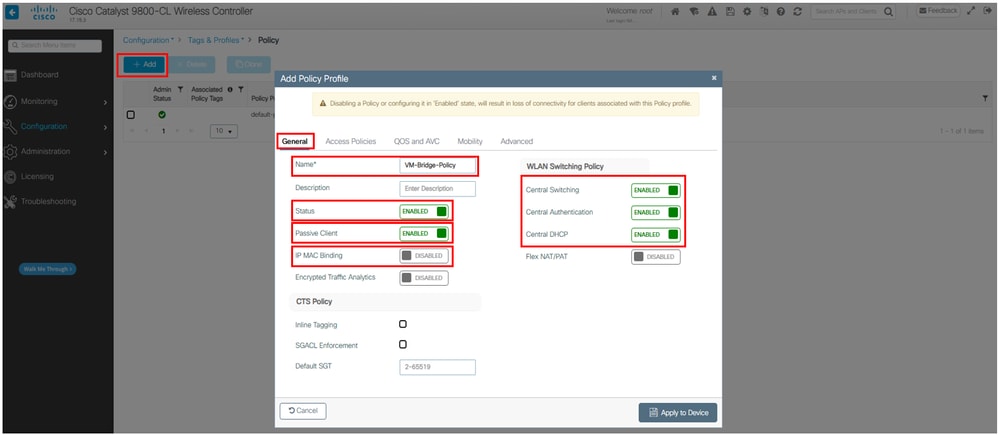
To ensure seamless connectivity for VMs configured with bridge adapters on the Cisco Catalyst 9800, it is essential to enable the Passive Client feature and disable IP MAC Binding. This setup allows the wireless controller to handle multiple IP addresses associated with a single MAC address, which is common in virtualize environments. Enabling Passive Client ensures traffic flow to the VM machine. Disabling IP-MAC Binding allows the controller to forward traffic to the VM machine without identifying it as IP Theft.
WLC GUI
Navigate to Configurations > Tags & Profile > Policy > Click + Add > General > WLAN Switching Policy > Central Switching ENABLED > Central Authentication ENABLED > Central DHCP ENABLED as shown in the image.
 Policy Configurations
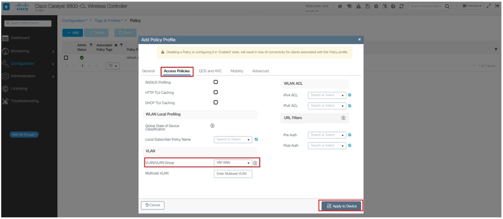
Navigate to Access Policies > VLAN > VLAN/VLAN Group > Configure VLAN > Click Apply to Device as shown in the image.
 Policy Configurations
WLC CLI
WLC#
WLC#config t
WLC(config)#wireless profile policy [WORD]
WLC(config-wireless-policy)#shutdown
WLC(config-wireless-policy)#passive-client
WLC(config-wireless-policy)#no ip mac-binding
WLC(config-wireless-policy)#central switching
WLC(config-wireless-policy)#central dchp
WLC(config-wireless-policy)#central authentication
WLC(config-wireless-policy)#vlan [WORD | VLAN ID]
WLC(config-wireless-policy)#no shutdown
WLC(config-wireless-policy)#end
WLC#

Warning: Disabling a Policy or configuring it in the enabled state, result in loss of connectivity for clients associated with this Policy profile.
WLAN Configurations
The example illustrates a WLAN configured for Pre-Shared Key (PSK) authentication. However, a WLAN can be configured for 802.1X authentication for a VM using bridge adapter.
Navigate to Configurations > Tags & Profile > WLAN > Click + Add > General > Profile Name "Custom Name" > SSID "Custom Name" > WLAN ID* "Custom Name" > Status ENABLED > Click Apply to Device as shown in the image.
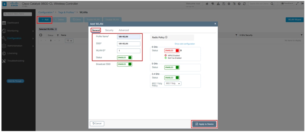 WLAN Configurations
Navigate to Security > Layer2 > PSK "check box" > PSK Format ASCII > PSK Type Unencrypted > Pre-Shared Key* "Custom Key" > Click Update & Apply to Device as shown in the image.
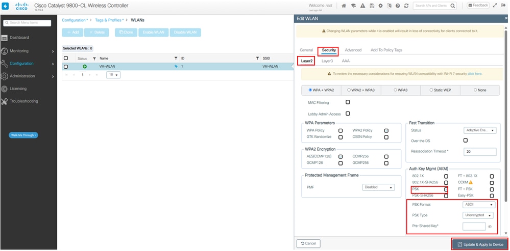 WLAN Configurations
WLC CLI
WLC#
WLC#config t
WLC(config)#wlan [WORD] [WLAN Identifier]
WLC(config-wlan)#shutdown
WLC(config-wlan)#security wpa akm psk
WLC(config-wlan)#no security wpa akm dot1x
WLC(config-wlan)#security wpa psk set-key ascii [WORD]
WLC(config-wlan)#no shutdown
WLC(config-wlan)#end
WLC#
Warning: Changing WLAN parameters while it is enabled results in loss of connectivity for clients connected to it.
Policy Tag Configurations
The example illustrates a Policy Tag configurations to bind a specific WLAN profile with a specific Policy profile.
Navigate to Configurations > Tags & Profile > TAG > Click + Add > Name "Custom Name" > WLAN-POLICY Maps: > Click + Add > WLAN Profile* "Select Custom WLAN" > Policy Profile* "Select Custom Policy" > Click the "blue check box" > Click Apply to Device as shown in the image.
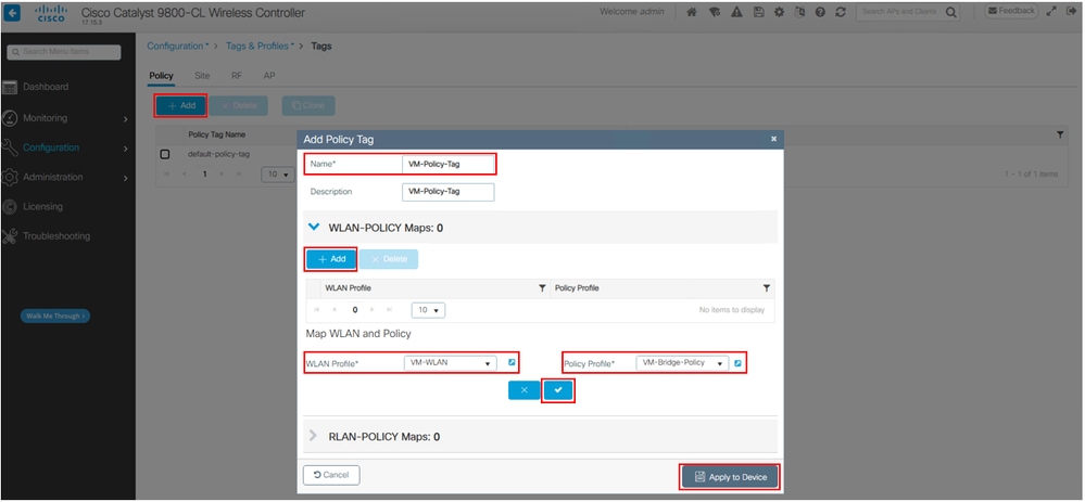 Policy Tag Configurations
WLC CLI
WLC#
WLC#config t
WLC(config)#wireless tag policy [WORD]
WLC(config-policy-tag)#wlan [WORD] policy [WORD]
WLC(config-policy-tag)#end
WLC#
VM Configurations
The Bridged Adapter feature enables a VM to directly access the host machine physical network.
Navigate to Setting > Network > Attached to: Select Bridged Adapter > Name: "Select Laptop Physical WiFi Adapter" > Promiscuous Mode: Select Allow All as shown in the image.
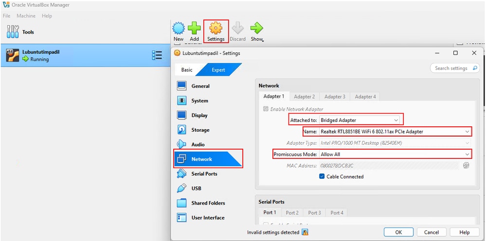 VM Configurations

Note: While this setup utilizes VirtualBox with an Ubuntu OS, the location and naming conventions for specific VM settings can differ depending on the virtualization platform being used.
Verify
From the VM and 9800 WLC, the configuration can be checked with these commands and methods.
VM Confirmation
To confirm that the VM has successfully obtained an IP address from the DHCP server, execute the ifconfig command within the VMs command-line interface. The output display the network configuration, including the assigned IP address if acquired via DHCP.
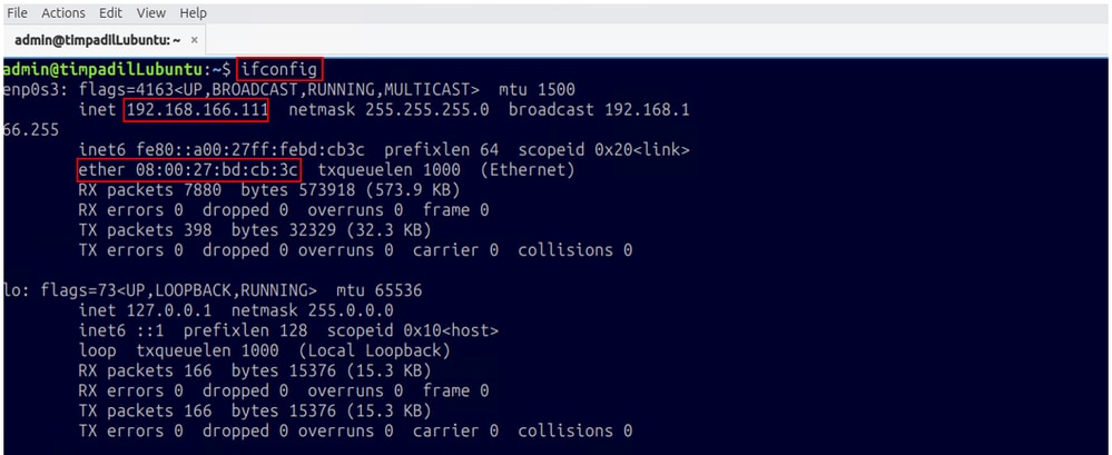 VM Command-Line Interface
Now perform a ping in the VMs command-line interface to verify gateway reachability.
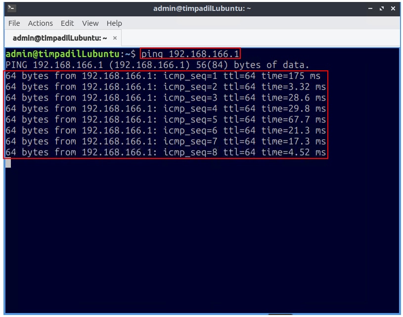 VM Command-Line Interface
Host VM Confirmation
Verify the IP and MAC address of the Host VM laptop.
Navigate to Host VM laptop CLI and perform the command ifconfig /all.
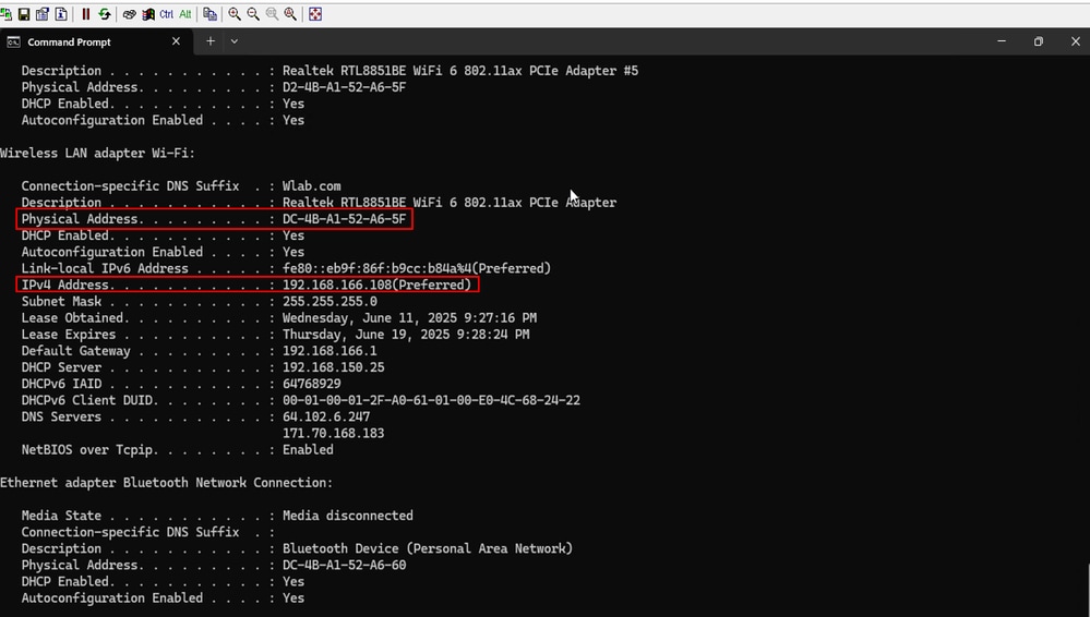 Host VM laptop
WLC Confirmation
WLC CLI
WLC#
WLC#show wireless profile policy detailed [WORD]
WLC#show wireless tag policy detailed [WORD]
WLC#show wlan name [WORD]
WLC#show vlan
WLC#show platform software arp broadcast
WLC#
Troubleshoot
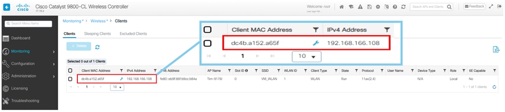
The WLC only displays the association details for the physical WiFi adapter of the Host VM laptop, including its IP address and MAC address. It does not recognize the VM as an associated client and does not display the VMs IP address or MAC address.
WLC Client Monitoring
The IP address 192.168.166.108 and MAC address dc4b.a152.a65f are assigned to the Host VM laptop. It is important to note that the IP and MAC addresses of the VM itself are not directly visible on the 9800 WLC. However, by performing a packet capture on the Wireless LAN Controller, you can observe the VMs IP address 192.168.166.111 being used as the Source Address for ICMP requests. Similarly, the ICMP replies utilize the VMs IP address as the Destination Address.
Navigate to Monitoring > Wireless > Clients as shown in the image. The image demonstrates that the IP and MAC addresses of the Host VM laptop are clearly visible within the Cisco 9800 WLCs GUI.
 WLC Client Monitoring
WLC Packet Capture
The example demonstrates a Packet Capture configurations on a 9800 WLC.
Navigate to Troubleshooting > Packet Capture > Click + Add > Capture Name* "Create Custom Name" > Filter* "any" > Buffer Size* "100" > Available "Select Interface" > Click Apply to Device as shown in the image.
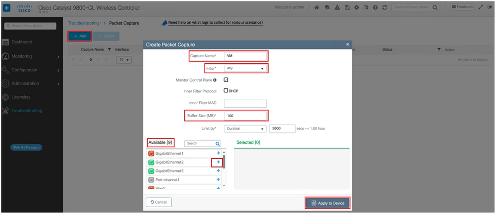 WLC Packet Capture Configurations
WLC CLI
WLC#
WLC#monitor capture [WORD] interface [Interface] [Interface Number] both
WLC#monitor capture [WORD] buffer size 100
WLC#monitor capture [WORD] match any
WLC#monitor capture [WORD] start
WLC#monitor capture [WORD] stop
WLC#monitor capture [WORD] export flash:[Name.pcap]
WLC#no monitor capture [WORD]
WLC# copy flash:<Name.pcap> tftp://<IP ADD>/<Name.pcap>
WLC#
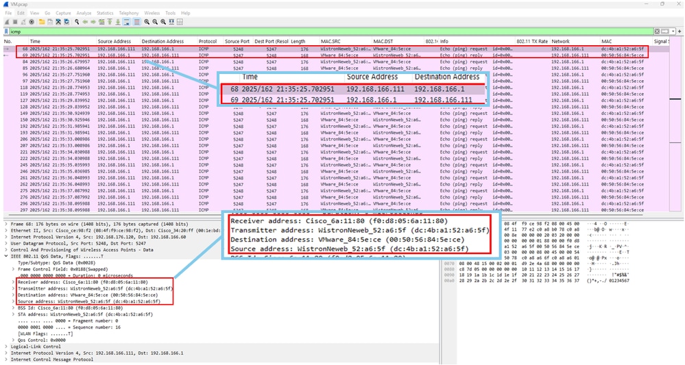
Wireshark Packet Capture
In the Wireshark packet capture, the VMs IP address 192.168.166.111 is observed as the Source Address for ICMP requests. Additionally, the ICMP replies uses the same IP address as the Destination Address.
- Receiver address is the AP MAC address
- Transmitter address is the Host VM laptop MAC address
- Destination address is the Gateway MAC address
- Source address is the Host VM laptop MAC address
The image shown is an example of the Wireshark packet capture of the VMs ICMP request to the gateway IP address (192.168.166.1).
 Wireshark Packet Capture
Related information
 Feedback