Configure and Troubleshoot Layer 3 Fluidity on IW Access Points on URWB Mode
Available Languages
Download Options
Bias-Free Language
The documentation set for this product strives to use bias-free language. For the purposes of this documentation set, bias-free is defined as language that does not imply discrimination based on age, disability, gender, racial identity, ethnic identity, sexual orientation, socioeconomic status, and intersectionality. Exceptions may be present in the documentation due to language that is hardcoded in the user interfaces of the product software, language used based on RFP documentation, or language that is used by a referenced third-party product. Learn more about how Cisco is using Inclusive Language.
Contents
Introduction
This document describes the configuration of a Fluidity Layer 3 setup for CURWB devices and provides practical guidance for troubleshooting the network.
The goal is to ensure a seamless setup process and to equip you with tools for resolving potential issues effectively.
Components Used
The configuration detailed in this document involves these hardware components:
- Cisco Catalyst IW9167
The information in this document was created from the devices in a specific lab environment. All of the devices used in this document started with a cleared (default) configuration. If your network is live, ensure that you understand the potential impact of any command.
What is Fluidity?
In the context of CURWB (Cisco Ultra-Reliable Wireless Backhaul), Fluidity is a network architecture built on Multiprotocol Label Switching (MPLS) technology, designed to deliver IP-encapsulated data efficiently.
In a CURWB mobility network, handoff processes occur when an existing link is broken, and a new link is established. This handoff resembles a network topology change, a critical challenge in high-speed mobility scenarios.
Conventional mechanisms for detecting such changes and reconfiguring nodes are often too slow and data-intensive, leading to suboptimal performance.
To overcome these limitations, Fluidity introduces a fast handoff solution that provides rapid path reconfiguration with latency as low as one millisecond. T
his mechanism enhances real-time performance in high-mobility scenarios by extending the network's control plane and leveraging a specialized manipulation technique for node MPLS Forwarding Information Base (FIB) tables.
In the Fluidity architecture, mobile nodes dynamically establish pseudo wires with trackside radios upon mutual detection.
As the vehicle moves along the track, it initiates handoff from one trackside radio to another based on predefined fluidity parameters, ensuring seamless connectivity and optimal performance
Need for Layer 3 Fluidity
Layer 3 Fluidity offers a range of capabilities that address mobility challenges in multi-network environments. Key advantages include:
- Seamless Handoff Across Subnets
Fluidity Layer 3 enables a vehicle to transition seamlessly between trackside base stations or radios that belong to different subnets.
- L2TP Tunnel Integration
This seamless connectivity is achieved using Layer 2 Tunneling Protocol (L2TP) tunnels. These tunnels connect the Mesh End at each network cluster or site to a centralized Fluidmesh Gateway device located at the network core, known as the Global Gateway.
- Centralized MPLS Routing
Each Global Gateway establishes an L2TP tunnel with the Mesh End at every network cluster or subnet. This configuration allows MPLS routing to occur at the Global Gateway, eliminating the need for conventional Layer 3 routing at each subnet.
- Uninterrupted Connectivity During Handoff
With Layer 3 Fluidity, vehicles can move between multiple trackside network clusters—each belonging to a different network or subnet—without losing end-to-end connectivity to the core network, even during handoff.
- Scalability Across Wide-Area Deployments
Layer 3 Fluidity is designed to scale across multiple network deployments and sites, even those separated by significant distances. It works seamlessly whether the sites are connected via private fiber-optic links or across public domain infrastructure such as ISPs.
- Flattening of Subnets for Seamless Routing
Fluidity Layer 3 operates on top of existing network infrastructures and "flattens" subnets using L2TP encapsulation. These encapsulations establish seamless routing and end-to-end connectivity for vehicles moving across multiple networks, all the way back to the core network.
Fluidity Layer 3 Key Concepts
- Communication between trackside subnets and the Global Gateway network relies on the customer-routed IP network, while connectivity to vehicle networks is established through MPLS and L2TP tunnels.
- Each trackside radio network requires at least one Mesh End, with networks on separate broadcast domains.
- Each Global Gateway must connect to the L2TP WAN address of every Mesh End
- Vehicle-mounted CURWB radios must have static routes for each local subnet, enabling address advertisement back to the Global Gateway for network convergence.
- The onboard router’s IP address must be set as the default gateway for vehicle radios
Network Topology for Layer 3 Fluidity
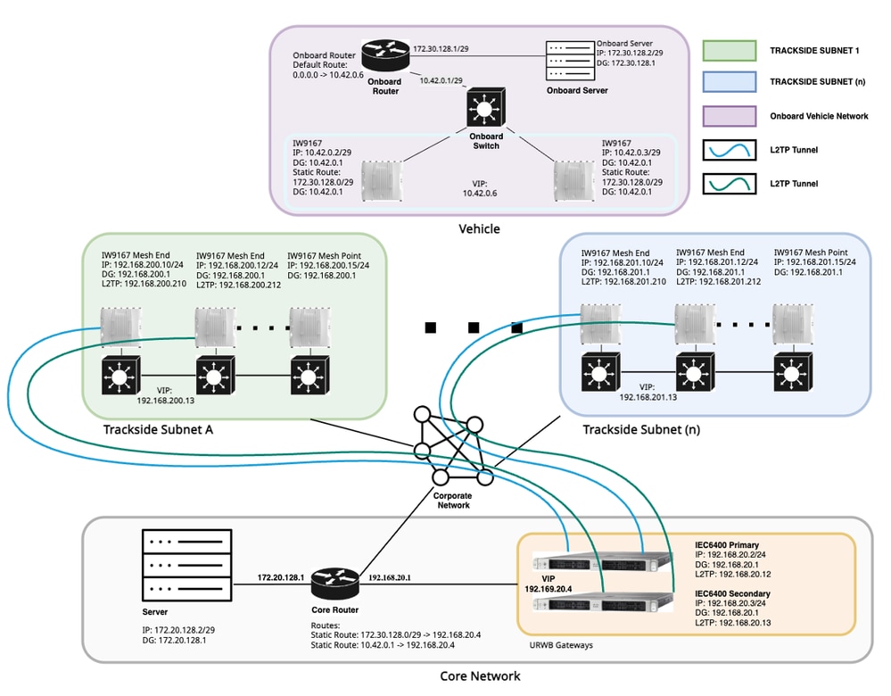
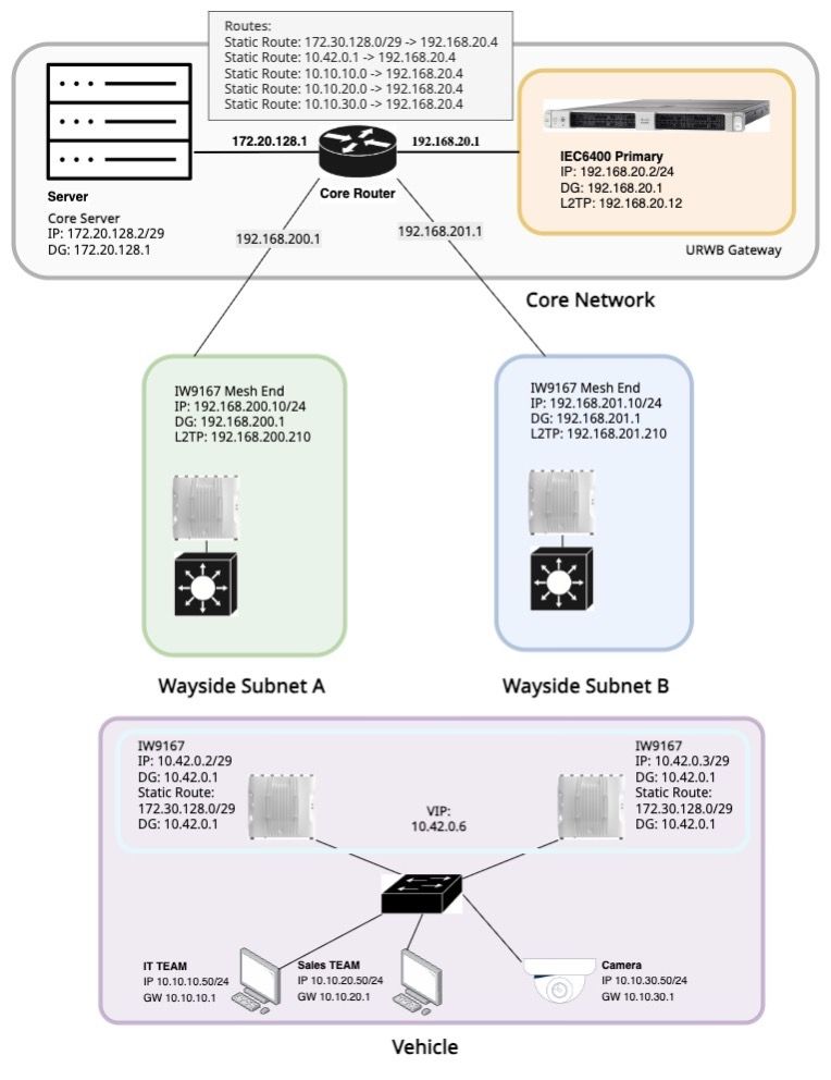
This document outlines the architecture of a Cisco Ultra-Reliable Wireless Backhaul (CURWB) Layer 3 network design.
This robust topology is engineered to facilitate seamless and reliable communication between moving vehicles and a fixed trackside infrastructure, ultimately integrating data into a centralized corporate network.
The design leverages Layer 3 routing to segment the network logically, ensuring efficient data flow and scalability across distinct operational domains.
Vehicle Segment: Each "Vehicle" is equipped with an Onboard Router, an Onboard Switch, Onboard Servers, and two IW9167 devices, providing critical hardware redundancy.
The Onboard Router acts as the primary gateway for the vehicle's internal network, connecting to the Onboard Switch, which in turn facilitates connectivity for the IW9167 devices and Onboard Servers.
Trackside Subnets: The infrastructure includes multiple "Trackside Subnets" (for example, Trackside Subnet A, Trackside Subnet n), each comprising various IW9167 radios, including both Mesh End and Mesh Point devices.
Each Trackside Subnet is designed with two Mesh End devices at its ingress/egress point, implementing a "fastfail" feature for hardware redundancy.
This setup allows each subnet section to represent a distinct geographical area, enabling vehicles to roam seamlessly between these areas while maintaining continuous connectivity with the corporate network.
Corporate Network: This central network serves as the backbone, connecting to all Trackside Subnets and housing the core infrastructure. It comprises a Core Server, a Core Router, and redundant URWB Gateways (Primary and Secondary IEC6400 devices).
The Core Router is responsible for aggregating traffic from the various Trackside Subnets and managing static routes to ensure efficient communication between the corporate network and both the vehicle and Trackside segments.
Network IP Configuration Summary
|
Component/Device |
IP Address |
Subnet |
Default Gateway |
L2TP Address |
Notes |
|
Vehicle Segment |
|||||
|
Onboard IW9167 (1) |
10.42.0.2 |
255.255.255.248 |
10.42.0.1 |
NA |
Static Route 172.30.128.0/29 > 10.42.0.1 VIP: 10.42.0.6 |
|
Onboard IW9167 (2) |
10.42.0.3 |
255.255.255.248 |
10.42.0.1 |
NA |
|
|
Onboard Server |
172.30.128.2 |
255.255.255.248 |
172.30.128.1 |
NA |
|
|
Onboard Router IW Interface |
10.42.0.1 |
255.255.255.248 |
|
||
|
Onboard Router Network Interface |
172.30.128.1 |
255.255.255.248 |
|||
|
Trackside Segment (Subnet A) |
|||||
|
Mesh End IW9167 (1) |
192.168.200.10 |
255.255.255.0 |
192.168.200.1 |
192.168.200.210 |
VIP 192.168.200.13 |
|
Mesh End IW9167 (2) |
192.168.200.12 |
255.255.255.0 |
192.168.200.1 |
192.168.200.212 |
|
|
Mesh Point IW9167 |
192.168.200.15 |
255.255.255.0 |
192.168.200.1 |
||
|
Trackside Segment (Subnet B) |
|||||
|
Mesh End IW9167 (1) |
192.168.201.10 |
255.255.255.0 |
192.168.201.1 |
192.168.201.210 |
VIP 192.168.201.13 |
|
Mesh End IW9167 (2) |
192.168.201.12 |
255.255.255.0 |
192.168.201.1 |
192.168.201.212 |
|
|
Mesh Point IW9167 |
192.168.201.15 |
255.255.255.0 |
192.168.201.1 |
||
|
Core Network Segment |
|||||
|
Gateway IEC6400 (1) |
192.168.20.2 |
255.255.255.0 |
192.168.20.1 |
192.168.20.12 |
VIP 192.168.20.4 |
|
Gateway IEC6400 (1) |
192.168.20.3 |
255.255.255.0 |
192.168.20.1 |
192.168.20.13 |
|
|
Core Router Gateway Interface |
192.168.20.1 |
255.255.255.0 |
Static Route: 172.30.128.0/29 -> 192.168.20.4 Static Route: 10.42.0.1 -> 192.168.20.4 |
||
|
Core Router Trackside Subnet A Interface |
192.168.200.1 |
255.255.255.0 |
|||
|
Core Router Trackside Subnet n Interface |
192.168.201.1 |
255.255.255.0 |
|||
|
Core Router Server Interface |
172.20.128.2 |
255.255.255.248 |
172.20.128.1 |
Configuring Layer 3 Fluidity
This document presents a basic Layer 3 configuration, highlighting only the essential settings required to establish connectivity between the core network and the vehicle network. Non-essential configurations and advanced features are not covered in this overview.
The configuration follows a design that incorporates hardware redundancy (FastFail) at Global Gateways, Local Mesh Ends, and Vehicle Radios, with the assumption that FastFail is already configured.
Notice that MPLS FastFail (HA) and VIP cannot be configured through the GUI and require the use of CLI or IW-Services. For detailed guidance on MPLS FastFail configuration, refer to this article:
Radio Configuration:
Configuring Layer 3 Fluidity Via GUI:
Configuring Global Gateways:
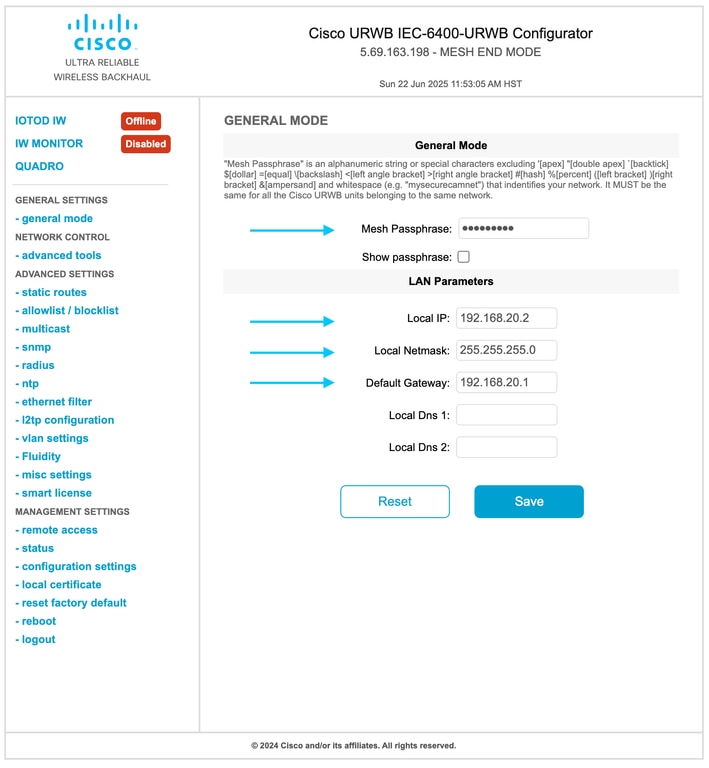
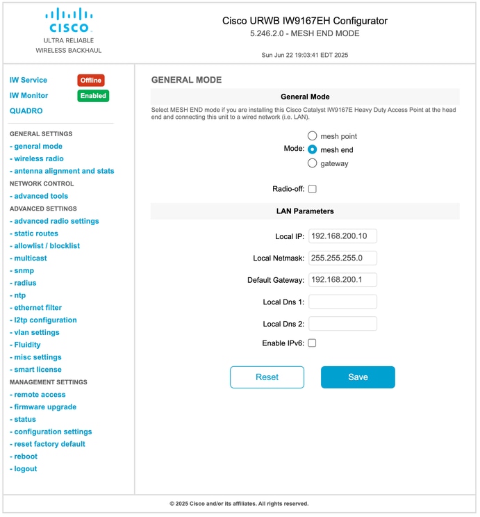
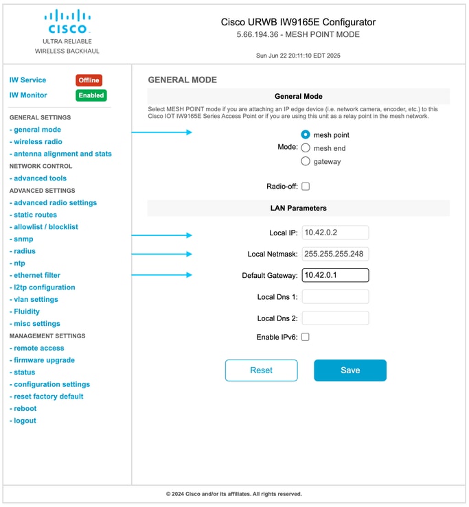
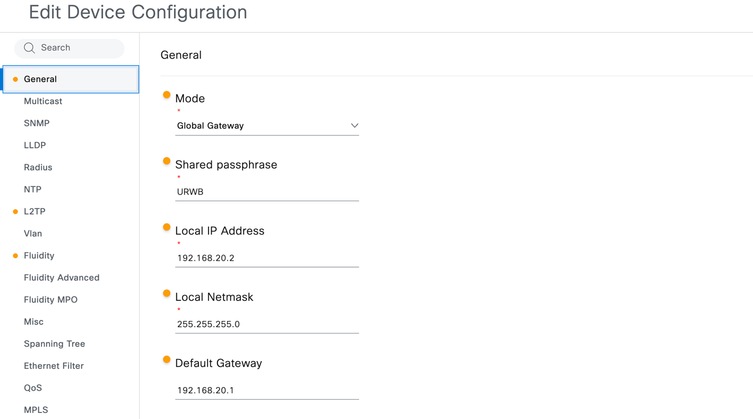
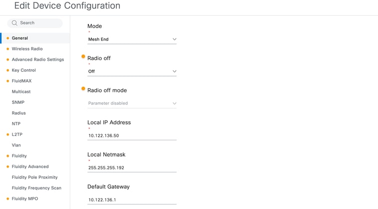
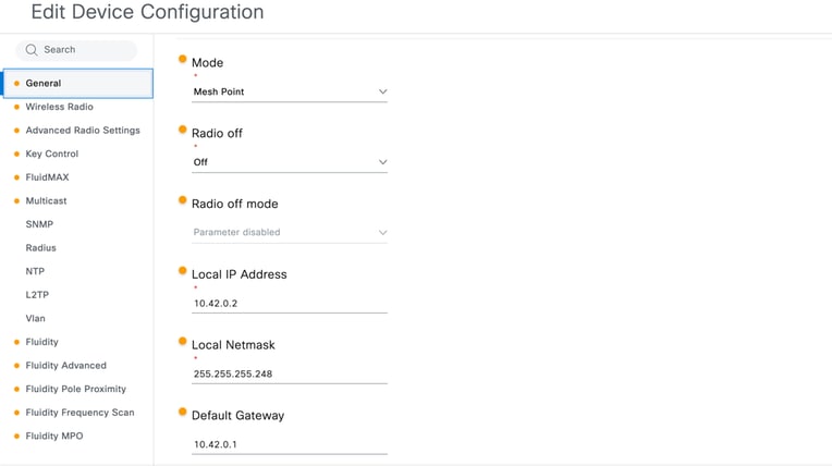
- GENERAL SETTINGS > General Mode:
IEC6400, when configured as a Global Gateway, is designed to serve as the ingress and egress point for the CURWB Layer 3 network, enabling core-to-vehicle connectivity. Gateway operation for IEC6400 is configured on the Fluidity page.
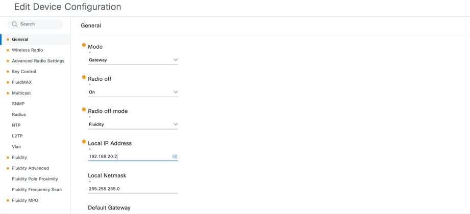
In contrast, when devices such as the IW9167 are used as a Global Gateway for a Layer 3 network, explicit gateway configuration is required on the General Mode page. Additionally, configuring IW radios in gateway mode disables the wireless interfaces, so the Radio-off mode must be set to Fluidity.
For the IEC-6400, the passphrase is configured on the General Mode page, whereas for other radios, it is set on the Wireless Radio page. It is essential to use the same passphrase for all trackside and vehicle devices to ensure connectivity.
The Local IP, Local Netmask, and Default Gateway for the device must be configured as required.
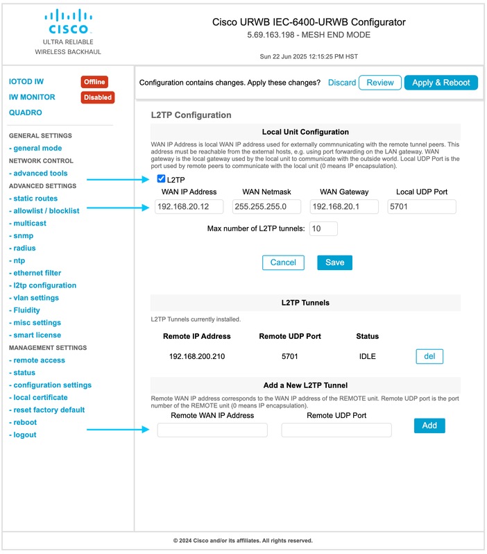
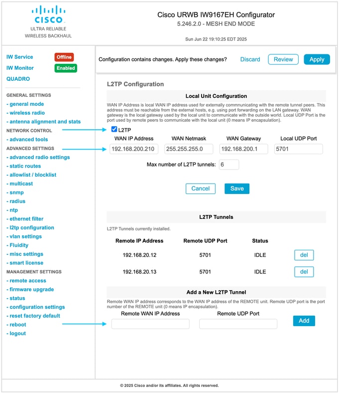
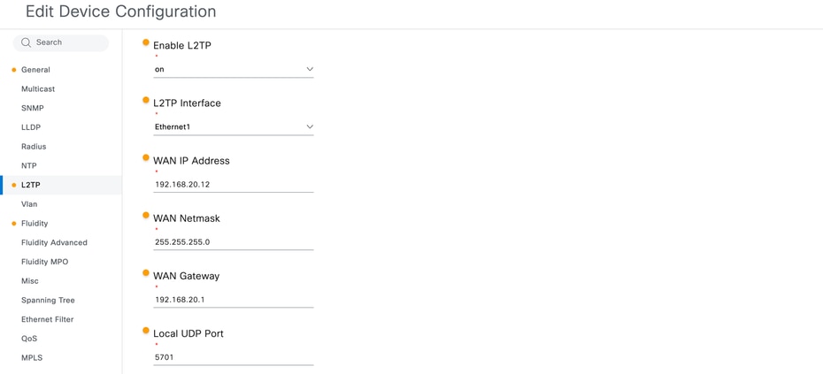
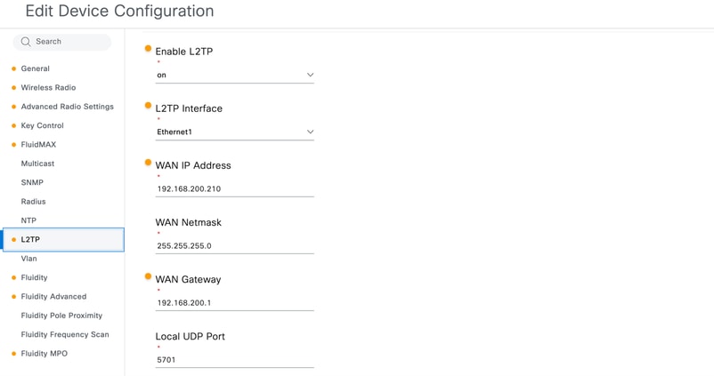
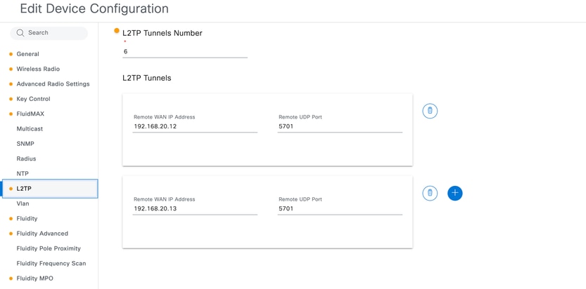
- ADVANCED SETTINGS > l2tp configuration:
On the L2TP configuration page, assign the L2TP WAN IP address within the same subnet as the gateway, and specify the WAN gateway as the gateway for this subnet. The local UDP port must be configured as 5701.
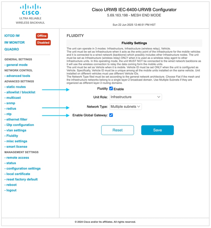
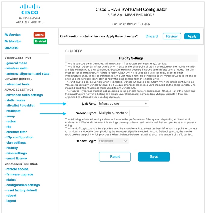
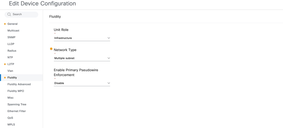
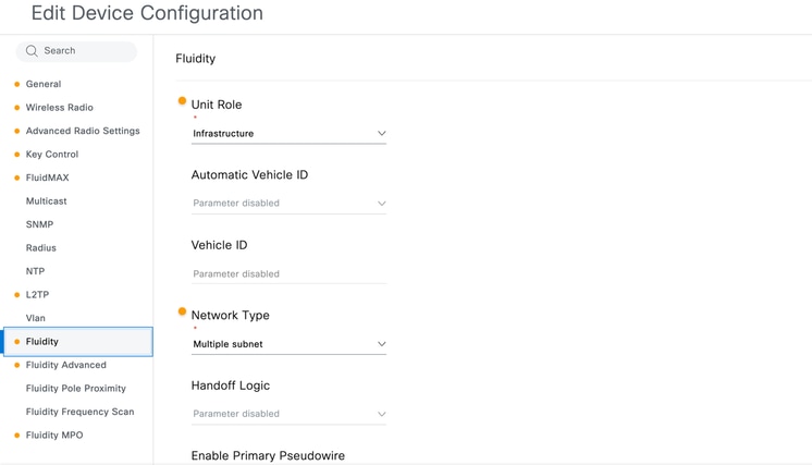
- ADVANCED SETTINGS > Fluidity:
On the Fluidity page, Fluidity mode must be enabled. The IEC6400 Unit Role can only be configured as Infrastructure. For Layer 3 operation, the Network Type must be set to Multiple Subnets, and the Global Gateway option must be selected.
Configuring Trackside Radios
- GENERAL SETTINGS > General Mode:
Configuration of the trackside radios is required next. Trackside radios may span multiple subnets, with radios under the same subnet forming a cluster. Each cluster must include dedicated Mesh End radios, which act as the ingress and egress point for that subnet of CURWB radios. One or two Mesh Ends can be configured, depending on whether high availability (HA) is required. The remaining trackside radios within the subnet must be configured as Mesh Points.
The Local IP, Local Netmask, and Default Gateway for the device must be configured as required.
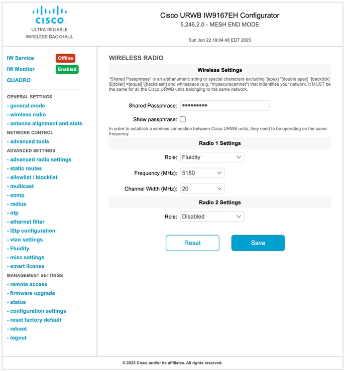
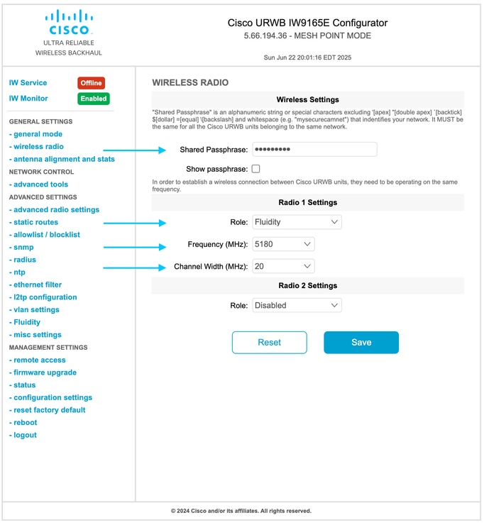
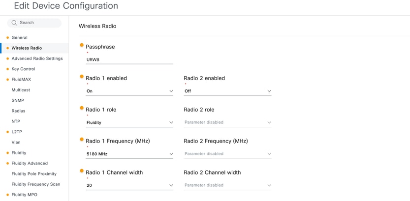
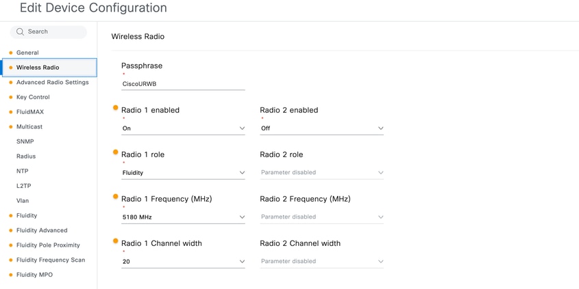
- GENERAL SETTINGS > Wireless Radio:
On the Wireless Radio page, it is essential to use the same passphrase as all other radios. The radio role for the wireless interface must be configured as Fluidity. While multiple wireless interfaces can be utilized for a radio based on project requirements, only Radio 1 is configured and Radio 2 is disabled in this lab setup for simplicity.
- ADVANCED SETTINGS > l2tp configuration:
On the L2TP configuration page, assign the L2TP WAN IP address within the same subnet as the gateway, and specify the WAN gateway as the gateway for this subnet. The local UDP port must be configured as 5701. This configuration is only required on mesh end radio(s) as Global gateway establishes the L2TP tunnel with the Mesh End radio(s) of each Subnet Clusters.
- ADVANCED SETTINGS > fluidity:
On the Fluidity page, Unit Role must be Infrastructure. For Layer 3 operation, the Network Type must be set to Multiple Subnets.
Configuring Vehicle Radios
- GENERAL SETTINGS > General Mode:
Configuration of the Vehicle radios is required next. Trackside radios may span multiple subnets, with radios under the same subnet forming a cluster. Each cluster must include dedicated Mesh End radios, which act as the ingress and egress point for that subnet of CURWB radios. One or two Mesh Ends can be configured, depending on whether high availability (HA) is required. The remaining trackside radios within the subnet must be configured as Mesh Points.
The Local IP, Local Netmask, and Default Gateway for the device must be configured as required.
- GENERAL SETTINGS > Wireless Radio:
On the Wireless Radio page, it is essential to use the same passphrase as all other radios. The radio role for the wireless interface must be configured as Fluidity. While multiple wireless interfaces can be utilized for a radio based on project requirements, only Radio 1 is configured, and Radio 2 is disabled in this lab setup for simplicity.
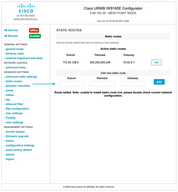
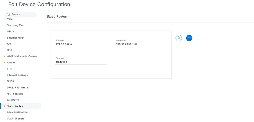
- ADVANCED SETTINGS > static routes:
If the vehicle network includes multiple subnets for onboard devices or servers, a static route must be configured on the onboard radio. In this configuration, the onboard subnet and netmask must be specified, with the gateway set to the corresponding interface on the onboard router.
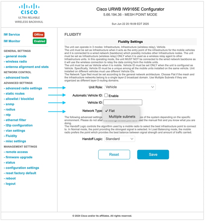
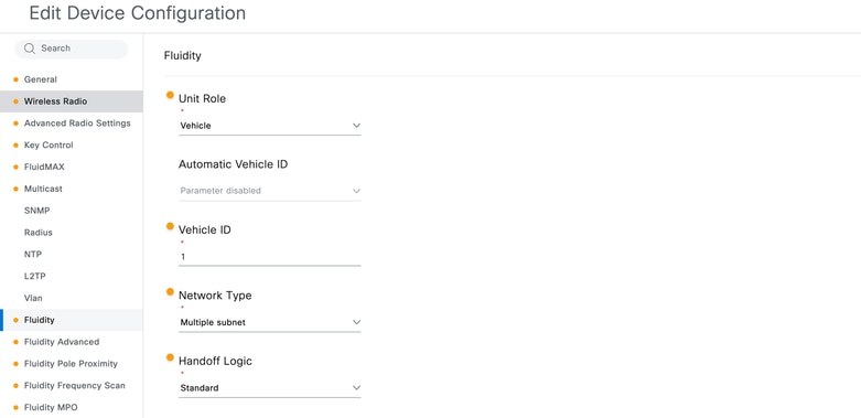
- ADVANCED SETTINGS > fluidity:
When configuring the vehicle radio, the Unit Role must be set to Vehicle. To enable Multiple Subnets as the Network Type, Automatic Vehicle ID must first be unchecked. Unique Vehicle IDs must be assigned to radios in each vehicle; however, if multiple radios are present on the same vehicle, the same Vehicle ID must be configured for all of them. Finally, set the Network Type to Multiple Subnets.
Note:
While basic Layer 3 configuration can be performed through the GUI, configuring TITAN or VIP for mesh end devices requires the use of either the CLI or IW-Services, as these options are not available in the GUI.
Configuring Layer 3 Fluidity Via IW-Services in IoT OD
Configuring Global Gateways
- In General Section, Mode must be selected as Global Gateway, and Shared Passphrase, Local IP address, Local Netmask and Default Gateway needs to be configured.
While configuring IW916X radios as Gateway, note that Radio Off will be automatically enabled, Radio Off mode needs to be Fluidity.
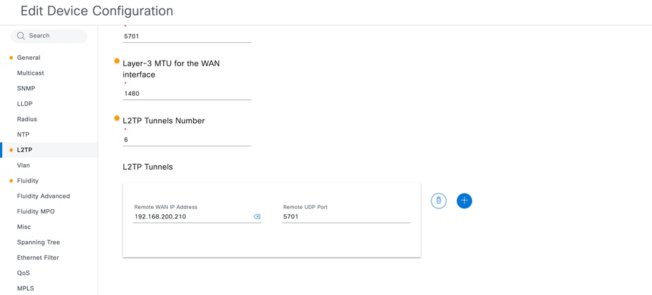
- In L2TP Section, WAN IP, WAN Netmask, WAN Gateway, ports. needs to be configured. At the same time L2TP Tunnels needs to be added.
- Finally, Fluidity needs to be enabled and Unit role must be Infrastructure, while network type must be multiple subnet.
Configuring Trackside Radios:
- In General Section, Mode must be selected as Mesh end, and Shared Passphrase, Local IP address, Local Netmask and Default Gateway needs to be configured.
Note: But for the mesh point trackside radios Mode will be Mesh point
- In Wireless Radio Section, Passphrase, Radio Interface (which you want to use communicate to the vehicle), Frequency and passphrase needs to be configured
- In L2TP Section, WAN IP, WAN Netmask, WAN Gateway, ports. needs to be configured. At the same time L2TP Tunnels needs to be added.
- Finally, Fluidity needs to be enabled, and Unit role must be Infrastructure, while network type must be multiple subnet
Configuring Vehicle Radios
- In General Section, Mode must be selected as Mesh end, and Shared Passphrase, Local IP address, Local Netmask and Default Gateway needs to be configured.
- In Wireless Radio Section, Passphrase, Radio Interface (which you want to use communicate to the trackside), Frequency and passphrase needs to be configured
- Finally, Fluidity needs to be enabled, and Unit role must be Vehicle, and Vehicle ID must be manually selected while network type must be multiple subnet
-
If the vehicle network includes multiple subnets for onboard devices or servers, a static route must be configured on the onboard radio. In this configuration, the onboard subnet and netmask must be specified, with the gateway set to the corresponding interface on the onboard router.
Configuring Layer 3 Fluidity Via CLI
This section outlines the CLI configuration for CURWB devices, based on the topology presented at the beginning of the article. It is assumed that FastFail redundancy is implemented at the Global Gateway, Trackside Mesh End, and Vehicle. For specific FastFail redundancy configuration steps, refer to the previously mentioned article. Only the VIP concept specific to Layer 3 Fluidity is covered here, with the assumption that FastFail has already been configured on all required radios.
Configuring Global Gateways
Configure IEC6400 as Gateway
iotod-iw configure offline

### BASIC CONFIG ###

modeconfig passphrase URWB
ip addr 192.168.20.2 netmask 255.255.255.0 gateway 192.168.20.1
modeconfig layer 3 mode gateway
l2tp wan 192.168.20.12 255.255.255.0 192.168.20.1 port 5701
l2tp add 192.168.200.210 5701

### APPLY CONFIG ###

write
reboot
Configure AP radios as Gateway:
configure iotod-iw offline

### BASIC CONFIG ###

configure ap address ipv4 static 192.168.20.2 255.255.255.0 192.168.20.1
configure modeconfig mode gateway
configure modeconfig mode meshend radio-off fluidity
configure wireless passphrase URWB
configure fluidity id infrastructure
configure l2tp wan 192.168.20.12 255.255.255.0 192.168.20.1
configure l2tp port 5701
configure l2tp add 192.168.200.210 5701
mpls fastfail primary 192.169.20.4       // Set the virtual IP address of the redundant device group in Layer-3 scenarios

### APPLY CONFIG ###

write
Reload
Configuring Trackside Radios
configure iotod-iw offline

### BASIC CONFIG ###

configure ap address ipv4 static 192.168.200.10 255.255.255.0 192.168.200.1
configure modeconfig mode meshend            //Applicable for only Mesh End Trackside Radio
configure modeconfig mode meshpoint         //Applicable for only Mesh point Trackside Radio
configure wireless passphrase URWB
configure dot11Radio 1 enable
configure dot11Radio 1 channel 149
configure dot11Radio 1 band-width 20
configure dot11Radio 1 antenna ab-antenna
configure dot11Radio 1 antenna gain 10
configure dot11Radio 1 txpower-level AUTO
configure dot11Radio 1 mode fluidity
configure dot11Radio 2 disable
mpls fastfail primary 192.168.200.13 // Set the virtual IP address of the redundant device group in Layer-3 scenarios
configure modeconfig mode meshend mpls layer 3  //Applicable for only Mesh End Trackside Radio
configure modeconfig mode meshpoint mpls layer 3  //Applicable for only Mesh point Trackside Radio
configure fluidity id infrastructure

## L2TP CONFIG ## //Applicable only to the mesh end Trackside radios

configure l2tp wan 192.168.200.210 255.255.255.0 192.168.200.1
configure l2tp port 5701
configure l2tp add 192.168.20.12 5701
configure l2tp add 192.168.20.13 5701

### APPLY CONFIG ###

write
Reload
Configuring Vehicle Radios.
configure iotod-iw offline

### BASIC CONFIG ###

configure ap address ipv4 static 10.42.0.2 255.255.255.248 10.42.0.1
configure modeconfig mode meshpoint
configure wireless passphrase URWB
configure dot11Radio 1 enable
configure dot11Radio 1 channel 149
configure dot11Radio 1 band-width 20
configure dot11Radio 1 antenna ab-antenna
configure dot11Radio 1 antenna gain 10
configure dot11Radio 1 txpower-level AUTO
configure dot11Radio 1 mode fluidity
configure dot11Radio 2 disable
configure modeconfig mode meshpoint mpls layer 3
configure fluidity id vehicle-id 1
configure ip route add 172.30.128.0 255.255.255.248 10.42.0.1
mpls fastfail primary 10.42.0.6 // Set the virtual IP address of the redundant device group in Layer-3 scenarios

### APPLY CONFIG ###

write
Reload
Switch/Router Configuration:
Core Router Configuration:
configure terminal
ip route 172.30.128.0 255.255.255.248 192.168.20.4
ip route 10.42.0.1 255.255.255.248 192.168.20.4
exit
write
Onboard Router Configuration:
configure terminal
ip route 0.0.0.0 0.0.0.0 10.42.0.6
exit
write
CURWB L3 Variations for Onboard network
Onboard Managed L2 Switch and No Router
- This configuration describes a hybrid Layer 3 network environment in which trunked VLANs are present on moving vehicles.
- It is intended for vehicle units that do not have an onboard router.
- In this setup:
- VLANs must be configured on the onboard vehicle radio.
- VLAN functionality must be disabled on all infrastructure units and global gateways.
- This approach helps maintain connectivity between local subnets and the core network.
- Note: In this application, onboard radios do not replace the Layer 3 device that is typically responsible for inter-VLAN routing in standard Fluidity Layer 3 topologies.
Variation of Network Topology for Layer 3 Fluidity with no Onboard Router
Configuration of the Onboard Switch
Switch#show vlan brief

VLAN Name                Status              Ports
---- -------------------------------- --------- -------------------------------
1    default             active               Gi1/0/3, Gi1/0/6, Gi1/0/7
                                              Gi1/0/8, Gi1/0/9, Gi1/0/10
                                              Gi1/0/13, Gi1/0/22
10   IT                  active               Gi1/0/16
20   SALES               active               Gi1/0/17
30   CAMERA              active               Gi1/0/18
1002 fddi-default        act/unsup
1003 token-ring-default  act/unsup
1004 fddinet-default     act/unsup
1005 trnet-default       act/unsup


Switch #show interfaces trunk


Port             Mode       Encapsulation           Status              Native vlan
Gi1/0/23         on         802.1q                  trunking                    100
Gi1/0/24         on         802.1q                  trunking                    100


Port             Vlans allowed on trunk
Gi1/0/23         1-4094
Gi1/0/24         1-4094


Port             Vlans allowed and active in management domain
Gi1/0/23         1,10,20,30,60,100
Gi1/0/24         1,10,20,30,60,100


Port             Vlans in spanning tree forwarding state and not pruned
Gi1/0/23         1,10,20,30,60,100
Gi1/0/24         1,10,20,30,60,100
Configuration of the Onboard Radio
- VLAN must be enabled only on the Vehicle units with no on-board router.
configure vlan status enabled
configure vlan management 60
configure vlan native 60- It’s important to add the static routes so the vehicle units can advertise the local subnets to the Global Gateways. The gateway for the subnets is the virtual IP used for the 2 on-board radios. In case of a single radio, the IP address of that radio must be used as the gateway.
configure ip route add 10.10.10.0 255.255.255.0 10.42.0.6
configure ip route add 10.10.20.0 255.255.255.0 10.42.0.6
configure ip route add 10.10.30.0 255.255.255.0 10.42.0.6
Configuration of the Core Router
configure terminal
ip route 10.10.10.0 255.255.255.0  192.168.20.4
ip route 10.10.20.0 255.255.255.0  192.168.20.4
ip route 10.10.30.0 255.255.255.0  192.168.20.4
exit
write
CURWB Layer 3 Network Troubleshooting:
In a Fluidity L3 network scenario, the L2TP tunnels status is one of the most important settings to check; in fact, a L2TP tunnel toward a cluster that is in IDLE or WAIT status or not properly configured, prevents the communication between the vehicle and backbone when the vehicle is connected to that specific cluster.
A simple way to check the tunnel status would be either to go on CLI and run “show l2tp” or from GUI check the status.
L2TP Tunnel Verification
- L2TP page shows the current L2TP tunnels and their status (CONN, WAIT, IDLE).
- When both Mesh End’s are up and running, on primary Mesh End the L2TP status will be in status CONN while on secondary Mesh End the L2TP status will be in status IDLE. If there connectivity issue in the Tunnel due to misconfiguration or physical issue, i twill be at WAIT
- From here it’s possible to check the current status and remove the L2TP tunnels already installed if needed.
- WAN IP address is unique to each device’s L2TP configuration and must be different from the device’s management IP address.
L2TP Status Summarization
- Each Global Gateway establishes a L2TP tunnel with each remote Mesh End
- Each cluster Mesh End establishes a L2TP tunnel with the Global Gateways
With the system in normal condition (all devices up and running), this is the expected scenario between the global gateways and each L3 Fluidity trackside cluster:
- L2TP Tunnel between Primary Global Gateway and Primary Mesh End – CONN
- L2TP Tunnel between Primary Global Gateway and Secondary Mesh End – IDLE
- L2TP Tunnel between Secondary Global Gateway and Primary Mesh End – IDLE
- L2TP Tunnel between Secondary Global Gateway and Secondary Mesh End – IDLE
Typical Configuration Issues / Things to Check
- Use of the same IP, WAN IP, or Virtual IP on multiple interfaces of the same device.
- Incorrect remote IP address configured; device is pointing to an IP that is not the correct WAN IP of the remote device.
- Duplicated WAN IP; two Mesh Ends within the same cluster are configured with the same WAN IP.
- Tunnel configured to establish over an Ethernet port that is not connected to the network.
- UDP port mismatch; local device and remote peer are using different UDP ports for traffic encapsulation.
Revision History
| Revision | Publish Date | Comments |
|---|---|---|
1.0 |
09-Jul-2025
|
Initial Release |
Contributed by Cisco Engineers
- Soumyajit RayTechnical Consulting Engineer
 Feedback
Contact Cisco
- Open a Support Case

- (Requires a Cisco Service Contract)