Introduction
This document describes how to configure AireOS Wireless LAN Controllers (WLC) to synchronize date and time with a Network Time Protocol (NTP) server.
Prerequisites
Requirements
Ensure that you meet these requirements before you attempt this configuration:
Components Used
The information in this document is based on these software and hardware versions:
The information in this document was created from the devices in a specific lab environment. All of the devices used in this document started with a cleared (default) configuration. If your network is live, ensure that you understand the potential impact of any command.
Manage System Date and Time on the Wireless LAN Controller
On a WLC, the system date and time can be manually configured from the WLC or configured to obtain the date and time from an NTP server.
The system date and time can be manually configured in the CLI configuration wizard or the WLC GUI/CLI.
This document provides a configuration example to synchronize the WLC system date and time through an NTP server.
NTP is a network protocol for clock synchronization between computer systems over variable-latency data networks to synchronize the clocks of computers to some time reference. The RFC 1305 and RFC 5905 provide detailed information on NTPv3 and NTPv4 implementation, respectively.
An NTP network usually receives its time from an authoritative time source, such as a radio clock or an atomic clock attached to a time server. NTP then distributes this time across the network.
An NTP client makes a transaction with its server over the poll interval, which dynamically changes over time and depends on the network conditions between the NTP server and the client.
NTP uses the concept of a stratum to describe how many NTP hops away a machine is from an authoritative time source. For example, a stratum 1 time server has a radio or atomic clock directly attached to it. It then sends its time to a stratum 2 time server through NTP, and so forth.
For more information on the best practices for NTP deployment, refer toUse Best Practices for Network Time Protocol.
The example in this document uses a Cisco Catalyst 3560-CX Series L3 Switch as an NTP server. The WLC is configured to synchronize its date and time with this NTP server.
Configure
Network Diagram
WLC ---- 3560-CX L3 Switch ---- NTP server
Configurations
Configure the L3 Switch as an Authoritative NTP Server
Use this command in global configuration mode if you want the system to be an authoritative NTP server, even if the system is not synchronized to an outside time source:
#ntp master !--- Makes the system an authoritative NTP server
Configure NTP Authentication
If you want to authenticate the associations with other systems for security purposes, use the next commands. The first command enables the NTP authentication feature.
The second command defines each of the authentication keys. Each key has a key number, a type, and a value. Currently, the only key type supported is md5.
Third, a list of trusted authentication keys is defined. If a key is trusted, this system is ready to synchronize to a system that uses this key in its NTP packets. In order to configure NTP authentication, use these commands in global configuration mode:
#ntp authenticate

!--- Enables the NTP authentication feature

#ntp authentication-key number md5 value

!--- Defines the authentication keys

#ntp trusted-key key-number

!--- Defines trusted authentication keys
Here is an example NTP Server configuration on the 3560-CX L3 Switch. The switch is the NTP master, which means the router acts as the authoritative NTP server but itself gets the time from another NTP server xxxx.xxx.
(config)#ntp authentication-key 1 md5 1511021F0725 7
(config)#ntp authenticate
(config)#ntp trusted-key 1
(config)#ntp master
(config)#ntp server xxxx.xxx
Configure the WLC for the NTP Server
From version 8.6 you can enable NTPv4. You can also configure an authentication channel between the controller and the NTP server.
In order to configure NTP authentication in the controller GUI, perform these steps:
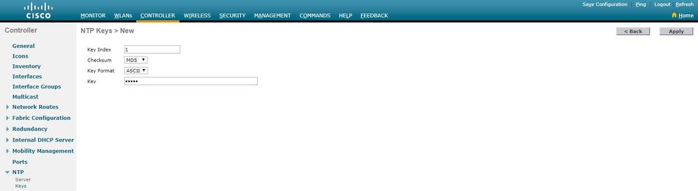
1. Choose Controller > NTP > Keys.
2. Click New to create a key.
3. Enter the key index in the Key Index text box.
4. Choose the Key Checksum (MD5 or SHA1) and the Key Format drop-down list.
5. Enter the Key in the Key text box:
6. Choose Controller > NTP > Servers to open the NTP Servers page. Select version 3 or 4 and then click New to add an NTP server. The NTP Servers > New page appears.
7. Select the Server Index (Priority).
8. Enter the NTP server IP Address in the Server IP Address text box.
9. Enable NTP server authentication, select the NTP Server Authentication check box and select the Key Index configured previously.
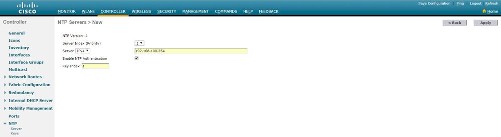
10. Click Apply.
In order to configure NTP authentication via the controller CLI, track this command tree:
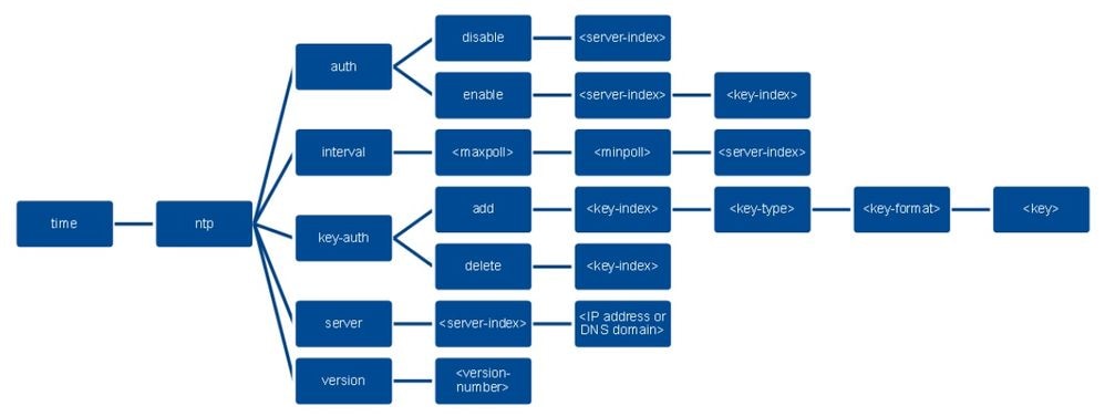
>config time ntp version 4
>config time ntp key-auth add 1 md5 ascii cisco
>config time ntp server 1 192.168.100.254
>config time ntp auth enable 1 1
Verify
On the NTP Server
#show ntp status
Clock is synchronized, stratum 3, reference is x.x.x.x
nominal freq is 286.1023 Hz, actual freq is 286.0901 Hz, precision is 2**21
ntp uptime is 6591900 (1/100 of seconds), resolution is 3496
reference time is E007C909.80902653 (09:23:21.502 UTC Fri Feb 8 2019)
clock offset is 0.3406 msec, root delay is 59.97 msec
root dispersion is 25.98 msec, peer dispersion is 1.47 msec
loopfilter state is 'CTRL' (Normal Controlled Loop), drift is 0.000042509 s/s
system poll interval is 128, last update was 7 sec ago.

#show ntp associations

 address ref clock st when poll reach delay offset disp
*~x.x.x.x y.y.y.y 2 20 1024 17 13.634 0.024 1.626
 ~127.127.1.1 .LOCL. 7 9 16 377 0.000 0.000 0.232
 * sys.peer, # selected, + candidate, - outlyer, x falseticker, ~ configured

#show ntp information
Ntp Software Name : Cisco-ntpv4
Ntp Software Version : Cisco-ntpv4-1.0
Ntp Software Vendor : CISCO
Ntp System Type : Cisco IOS / APM86XXX
On the WLC
In the GUI
While the WLC establishes the communication:

After connection is established:
In the WLC CLI
(Cisco Controller) >show time
Time............................................. Fri Feb 8 10:14:47 2019
Timezone delta................................... 0:0
Timezone location................................
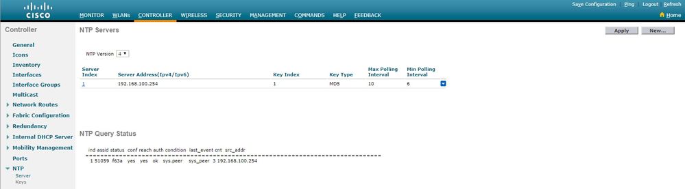
NTP Servers
NTP Version.................................. 4
Index NTP Key NTP Server NTP Key Polling Intervals
Index Type Max Min
-----------------------------------------------------------
1 1 192.168.100.254 MD5 10 6
NTPQ status list of NTP associations
assoc
ind assid status conf reach auth condition last_event cnt src_addr
===============================================================================
1 1385 f63a yes yes ok sys.peer sys_peer 3 192.168.100.254
(Cisco Controller) >
Troubleshoot
On the NTP server side that runs Cisco IOS, you can use debug ntp all enable command:
#debug ntp all
NTP events debugging is on
NTP core messages debugging is on
NTP clock adjustments debugging is on
NTP reference clocks debugging is on
NTP packets debugging is on
#
(communication between SW and NTP server xxxx.xxx)
Feb 8 09:52:30.563: NTP message sent to x.x.x.x, from interface 'Vlan1' (192.168.1.81).
Feb 8 09:52:30.577: NTP message received from x.x.x.x on interface 'Vlan1' (192.168.1.81).
Feb 8 09:52:30.577: NTP Core(DEBUG): ntp_receive: message received
Feb 8 09:52:30.577: NTP Core(DEBUG): ntp_receive: peer is 0x0D284B34, next action is 1.

(communication between SW and WLC)
Feb 8 09:53:10.421: NTP message received from 192.168.100.253 on interface 'Vlan100' (192.168.100.254).
Feb 8 09:53:10.421: NTP Core(DEBUG): ntp_receive: message received
Feb 8 09:53:10.421: NTP Core(DEBUG): ntp_receive: peer is 0x00000000, next action is 3.
Feb 8 09:53:10.421: NTP message sent to 192.168.100.253, from interface 'Vlan100' (192.168.100.254).

(communication between SW and NTP server xxxx.xxx)
Feb 8 09:53:37.566: NTP message sent to x.x.x.x, from interface 'Vlan1' (192.168.1.81).
Feb 8 09:53:37.580: NTP message received from x.x.x.x on interface 'Vlan1' (192.168.1.81).
Feb 8 09:53:37.580: NTP Core(DEBUG): ntp_receive: message received
Feb 8 09:53:37.580: NTP Core(DEBUG): ntp_receive: peer is 0x0D284B34, next action is 1.

(communication between SW and WLC)
Feb 8 09:54:17.421: NTP message received from 192.168.100.253 on interface 'Vlan100' (192.168.100.254).
Feb 8 09:54:17.421: NTP Core(DEBUG): ntp_receive: message received
Feb 8 09:54:17.421: NTP Core(DEBUG): ntp_receive: peer is 0x00000000, next action is 3.
Feb 8 09:54:17.421: NTP message sent to 192.168.100.253, from interface 'Vlan100' (192.168.100.254).
On the WLC side:
 >debug ntp ?

detail Configures debug of detailed NTP messages.
low Configures debug of NTP messages.
packet Configures debug of NTP packets.

(at the time of writte this doc there was Cisco bug ID CSCvo29660
on which the debugs of ntpv4 are not printed in the CLI. The below debugs are using NTPv3.)
(Cisco Controller) >debug ntp detail enable
(Cisco Controller) >debug ntp packet enable
(Cisco Controller) >*emWeb: Feb 08 11:26:53.896: ntp Auth key Info = -1

*emWeb: Feb 08 11:26:58.143: ntp Auth key Info = -1

*emWeb: Feb 08 11:26:58.143: ntp Auth key Info = -1

*emWeb: Feb 08 11:26:58.143: Key Id = 1 found at Local Index = 0

*sntpReceiveTask: Feb 08 11:26:58.143: Initiating time sequence

*sntpReceiveTask: Feb 08 11:26:58.143: Fetching time from:192.168.100.254

*sntpReceiveTask: Feb 08 11:26:58.143: Started=3758614018.143350 2019 Feb 08 11:26:58.143

*sntpReceiveTask: Feb 08 11:26:58.143: hostname=192.168.100.254 hostIdx=1 hostNum=0
*sntpReceiveTask: Feb 08 11:26:58.143: Looking for the socket addresses

*sntpReceiveTask: Feb 08 11:26:58.143: NTP Polling cycle: accepts=0, count=5, attempts=1,
retriesPerHost=6. Outgoing packet on NTP Server on socket 0:

*sntpReceiveTask: Feb 08 11:26:58.143: sta=0 ver=3 mod=3 str=15 pol=8 dis=0.000000 ref=0.000000

*sntpReceiveTask: Feb 08 11:26:58.143: ori=0.000000 rec=0.000000
*sntpReceiveTask: Feb 08 11:26:58.143: tra=3758614018.143422 cur=3758614018.143422

*sntpReceiveTask: Feb 08 11:26:58.143: Host Supports NTP authentication with Key Id = 1

*sntpReceiveTask: Feb 08 11:26:58.143: NTP Auth Key Id = 1 Key Length = 5

*sntpReceiveTask: Feb 08 11:26:58.143: MD5 Hash and Key Id added in NTP Tx packet

*sntpReceiveTask: Feb 08 11:26:58.143: 00000000: 1b 0f 08 00 00 00 00 00 00 00 00 00 00 00 00 00 ................
*sntpReceiveTask: Feb 08 11:26:58.143: 00000010: 00 00 00 00 00 00 00 00 00 00 00 00 00 00 00 00 ................
*sntpReceiveTask: Feb 08 11:26:58.143: 00000020: 00 00 00 00 00 00 00 00 e0 07 e6 02 24 b7 50 00 ............$.P.
*sntpReceiveTask: Feb 08 11:26:58.143: 00000030: 00 00 00 01 e4 35 f3 1a 89 f0 93 c5 51 c7 c5 23 .....5......Q..#
*sntpReceiveTask: Feb 08 11:26:58.143: 00000040: 01 dd 67 e0 ..g.
*sntpReceiveTask: Feb 08 11:26:58.143: Flushing outstanding packets

*sntpReceiveTask: Feb 08 11:26:58.143: Flushed 0 packets totalling 0 bytes

*sntpReceiveTask: Feb 08 11:26:58.143: Packet of length 68 sent to ::ffff:192.168.100.254 UDPport=123
*emWeb: Feb 08 11:26:58.143: ntp Auth key Info = 0

*emWeb: Feb 08 11:26:58.143: idx != 0 : ntp key Id = 1 Msg auth Status = 66

*sntpReceiveTask: Feb 08 11:26:58.146: Packet of length 68 received from ::ffff:192.168.100.254 UDPport=123
*sntpReceiveTask: Feb 08 11:26:58.146: Incoming packet on socket 0: has Authentication Enabled
*sntpReceiveTask: Feb 08 11:26:58.146: 00000000: 1c 04 08 eb 00 00 0e a0 00 00 0b 2e c3 16 11 07 ................
*sntpReceiveTask: Feb 08 11:26:58.146: 00000010: e0 07 e5 f8 d3 21 bf 57 e0 07 e6 02 24 b7 50 00 .....!.W....$.P.
*sntpReceiveTask: Feb 08 11:26:58.146: 00000020: e0 07 e6 02 24 e5 e3 b4 e0 07 e6 02 24 f3 c7 5a ....$.......$..Z
*sntpReceiveTask: Feb 08 11:26:58.146: 00000030: 00 00 00 01 32 e4 26 47 33 16 50 bd d1 37 63 b7 ....2.&G3.P..7c.
*sntpReceiveTask: Feb 08 11:26:58.146: KeyId In Recieved NTP Packet 1

*sntpReceiveTask: Feb 08 11:26:58.146: KeyId 1 found in recieved NTP packet exists as part of the trusted Key/s

*sntpReceiveTask: Feb 08 11:26:58.146: The NTP trusted Key Id 1 length = 5

*sntpReceiveTask: Feb 08 11:26:58.146: NTP Message Authentication - SUCCESS

*sntpReceiveTask: Feb 08 11:26:58.146: sta=0 ver=3 mod=4 str=4 pol=8 dis=0.043671 ref=3758614008.824734

*sntpReceiveTask: Feb 08 11:26:58.146: ori=3758614018.143422 rec=3758614018.144133
*sntpReceiveTask: Feb 08 11:26:58.146: Offset=-0.000683+/-0.002787 disp=1.937698

*sntpReceiveTask: Feb 08 11:26:58.146: best=-0.000683+/-0.002787

*sntpReceiveTask: Feb 08 11:26:58.146: accepts=1 rejects=0 flushes=0

*sntpReceiveTask: Feb 08 11:26:58.146: Correction: -0.000683 +/- 0.002787 disp=1.937698

*sntpReceiveTask: Feb 08 11:26:58.146: Setting clock to 2019 Feb 08 11:26:58.145 + 0.001 +/- 1.940 secs
*sntpReceiveTask: Feb 08 11:26:58.146: correction -0.001 +/- 1.938+0.003 secs - ignored


(Cisco Controller) >
Related Information
 Feedback