Configure and Troubleshoot Power over Ethernet in ACI
Available Languages
Download Options
Bias-Free Language
The documentation set for this product strives to use bias-free language. For the purposes of this documentation set, bias-free is defined as language that does not imply discrimination based on age, disability, gender, racial identity, ethnic identity, sexual orientation, socioeconomic status, and intersectionality. Exceptions may be present in the documentation due to language that is hardcoded in the user interfaces of the product software, language used based on RFP documentation, or language that is used by a referenced third-party product. Learn more about how Cisco is using Inclusive Language.
Contents
Introduction
This document describes POE and covers verification and troubleshooting for PoE in ACI.
What is Power Over Ethernet (POE)
Power over Ethernet is a technology that transmits both electrical power and network data over an ethernet cable. With PoE, each Ethernet interface of switches can supply power to devices like Voice over Internet Protocol(VoIP) phones,Internet Protocol Camera (IP camera) or security cameras, and wireless access points (AP). The PoE device like switches that supply power is called Power Sourcing Equipment (PSE). The power that is supplied is in Direct Current (DC) form. The device like IP phones or access points that are being powered is called a Powered Device (PD).
Currently, PoE-supported Top-of-rack Switches (TORs) are N9K-C9358GY-FXP, N9K-C9348GC-FXP and N9K-C93108TC-FX3P. POE supports different Power levels like 802.3af/at and max power up to 30W.
How PoE works
Power over Ethernet (PoE) operates by transmitting electrical power alongside data signals over standard Ethernet cables, typically Cat5e or Cat6. At the heart of PoE functionality is the power sourcing equipment (PSE), which can be a PoE-enabled network switch or an injector. When a Poe-compatible powered device (PD), such as a wireless access point or IP camera, is connected to the network, the PSE detects its presence. This detection triggers a negotiation process between the PSE and the PD, during which they communicate to determine power requirements and capabilities. The PSE then delivers power to the PD by injecting a low-voltage DC current into the Ethernet cable. This power is transmitted over the unused wire pairs in the Ethernet cable, typically pins 4/5 and 7/8 in an 8-wire cable, while data signals are transmitted over the other wire pairs. The PD receives the power and utilizes it to operate without the need for a separate power source. PoE standards, such as IEEE 802.3af, 802.3at (PoE+), and 802.3bt (PoE++) specify the maximum power levels that can be delivered over Ethernet cables, with newer standards supporting higher power requirements for devices with greater power demands.
Different software modules responsible for PoE operation
- PoE daemon(SUP): The daemon, which is located on the Supervisior (SUP) side of the switch, is at the heart of the PoE operation
- PoE USD (LC) : The Device Driver(USD),which is situated on the Line card(LC) site, is closer to the hardware layer or the PoE controller. It acts as a conduit between the daemon and the controller, and as we move forward, it is a responsible for all the controller or hardware level operations
- Link Layer Discovery Protocol (LLDP) and Cisco Discovery Protocol (CDP) for power negotiation : To negotiate and adjust power, we use LLDP and CDP. Once the power is enabled for the device, if it has the capabilities to support LLDP and CDP extended power TLVs(Type-Length Values), then power negotiation adjustment can be done using these protocols. We also have policy element changes for supporting PoE node policies and interface policies to enable this feature
- Application Policy Infrastructure Controller (APIC) GUI/CLI with Representational State Transfer Application Programming Interface (REST API) Integration for configuration
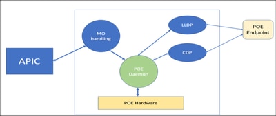
System Flow of Power over Ethernet (PoE)
- To simplify the process and reduce the load on our switches, a typical system flow involves the daemon communicating with the PoE hardware through USD
- The Managed Object (MO) handling is done through APIC, and there is interaction with LLDP and CDP
- Finally, the PoE endpoint is where the exchange of information takes place between the LLDP and CDP

PoE – Powered Device (PD) Detection
- The PoE Daemon triggers PD detection on a PoE-enabled port by activating detection on both the Titanium PoE controller hardware and the Portola USD PoE Controller hardware The Portola USD detects pre-standard Cisco PDs, while the Titanium controller detects IEEE-compliant PDs
- When the Portola USD detects a PD, it notifies the PoE Daemon via an Server-Sent Events (SSE) call. The USD sets the detection in continuous mode and sends a specific
Fast Link Pulse (FLP) to check for the return of the same FLP. If the same FLP is returned, it generates a DPMSTAT change interrupt back to the USD to notify the detection of the PD. The Physical Layer (PHY) then continues to do auto-negotiation to bring the link up
- If a Powered Device (PD) is not detected, the system tries to establish a link by auto-negotiation. If there is no PD connected and the link comes up, a linkup interrupt is generated, typically if the other side is a regular Network Interface Card (NIC)
- If the Power over Ethernet (PoE) daemon receives a linkup event before any detection event from PoEUSD, it stops both types of detection by making SSE calls to the USDs
- If the PoE daemon receives a detection event from the PoE USD, it assumes that the PD is IEEE compliant and uses the class information to decide on powering the PD. It also stops Cisco PD detection
- If the PoE daemon receives a detection event from the USD, it stops detection by the PoE Controller. The PoE daemon checks if power is available and accordingly directly notifies the PoE USD to enable power on the port
- Disconnect of either type of PDs is done by the PoE controller based on the current drawn by the port. On a PD disconnect, both forms of detection are started again
Configuration:
POE Configuration using APIC GUI.
To configure:
Step 1. Log in to the Cisco APIC GUI.
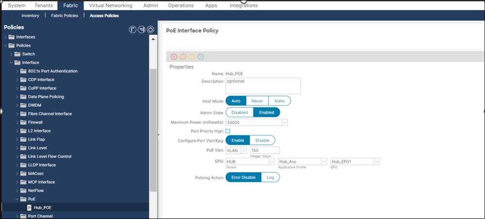
Step 2. On the menu bar, navigate to Fabric --> Access Policies-->Policy-->InterfacePOE
VLAN, EPG, Max power-related configuration can be defined on this page

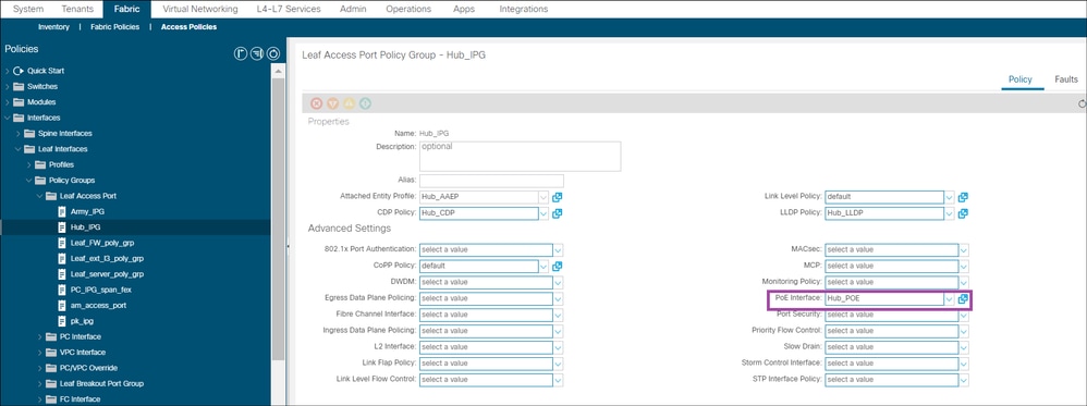
Step 3. On the menu bar, navigate to Access Policies-->Interface-->Policy Group-->Leaf Access Port
we configure Interface policy Group (IPG) under which we associate POE interface policy which we created in previous steps.

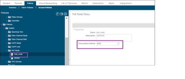
Step 4.On the menu bar, navigate to Access Policies-->Policies-->Switch-->POE Node
Here we have to define POE Node policy

Verify and Troubleshoot:
Power Over Ethernet Port States
If you have enabled Power over Ethernet (PoE) on a switch port, you can see one of the beneath PoE states on that port
- On: PoE is enabled on the port, and the supplied power comes from the power supply. The delivered power is then provided to the PoE-powered device (PD)
- Pwr-deny: PoE is enabled on the port, but the power cannot be supplied due to user configuration restrictions or insufficient power capacity of the Power Sourcing Equipment (PSE)
- Faulty:The port has experienced a fault condition. A faulty PoE port state can resolve on its own, or it require user intervention to correct the issue. In case of recoverable errors, the PoE daemon on the switch can be able to recover and reapply power based on configuration, class of the device, and installed power capacity. If you face recoverable errors, you can try changing the admin status of the port, changing the PoE-related interface configuration, or inserting and removing (OIR) the PD to bring the port out of error state
In the event of non-recoverable errors, the PoE daemon on the switch turn off power to the port
- Off: PoE is disabled on the port, and the port function as a typical data port
These states can be verified in inline power and details are mentioned in verification.
POE Verification via CLI
we are using Cisco CP-8841 for the verification and troubleshooting which is connected port Eth 1/7 on leaf
Leaf:
To confirm interface status on leaf:
1) Leaf# show interface ethernet 1/7 status

------------------------------------------------------------------------------------------------

 Port           Name                Status     Vlan       Duplex   Speed    Type

------------------------------------------------------------------------------------------------

 Eth1/7         --                  connected  trunk      full     1G       1g
To confirm state of POE and watts available or delivered we check power inline:
2) Leaf#show power inline

Module Available  Used    Remaining

       (Watts)   (Watts)   (Watts)

------ ---------  ------  ---------

1      305.0      7.4     297.6


Interface   Admin  Oper        Supplied  Delivered Device               IEEE  Max

                               (Watts)   (Watts)                        Class

---------   -----  ----        --------  --------- ------               ----- ---

Eth1/7      auto   on          7.4       6.5       Cisco IP Phone 8841  2     30.0


If we need to check power inline for specific interface we mention the interface:


Leaf# show power inline ethernet 1/7


Interface   Admin  Oper     Supplied  Delivered Device               IEEE  Max

                            (Watts)   (Watts)                        Class

---------   -----  ----     --------  --------- ------               ----- ---

Eth1/7      auto   on       7.4       6.5       Cisco IP Phone 8841  2     30.0


Interface   AdminPowerMax  AdminConsumption

            (Watts)        (Watts)

---------   -------------  ----------------

Eth1/7      30.0           3.9
To check the state and and internal PoE details:
3 ) Leaf# show system internal poe info ethernet 1/7

Interface name        :   Eth1/7

Interface mode        :   auto

Interface Priority    :   low

PD description        :   Cisco IP Phone 8841

Policer action        :   error disable

Max power             :   30.0

Default power         :   4.0

PS supplied power     :   7.4

PD Base power         :   7.0

Port delivered power  :   6.5

Port consumption pwr  :   3.9

Max drawn power       :   5.1

Policer measured pwr  :   0.0

PD Class              :   IEEE 2

PD Discovery mode     :   IEEE

PD Detection status   :   Delivering    <<<<<

Num violations        :   0
To check the detailed consumption:
4) Leaf# show power inline consumption

Interface            Consumption  Admin

                     Configured   Consumption (Watts)

----------           -----------  -------------------

Eth1/1               NO           15.4

Eth1/2               NO           15.4

Eth1/3               NO           15.4

Eth1/4               NO           15.4

Eth1/5               NO           15.4

Eth1/6               NO           15.4

Eth1/7               YES          4.0                    <<<<<

Eth1/8               NO           15.4
To check specific interface-related PoE event-history logs
5) Leaf# vsh -c "show system internal poe event-history interface ethernet 1/7"

FSM: <Ethernet1/7> has 4 logged transitions<<<<<

1.FSM:<Ethernet1/7> Transition at 2024-04-19T12:15:46.549+00:00T12:48:38.767242000+00:00

Previous state: [PORT_ST_POE_SHUT]

Triggered event: [POE_PORT_EV_START_DETECTION]

Next state: [PORT_ST_POE_DETECTING]  <-- Initial Status

2.FSM:<Ethernet1/7> Transition at 2024-04-19T12:15:46.549+00:00T12:50:03.337279000+00:00

Previous state: [PORT_ST_POE_DETECTING]

Triggered event: [POE_PORT_EV_START_DETECTION]

Next state: [No transition found]


3.FSM:<Ethernet1/7> Transition at 2024-04-19T12:16:53.135561000+00:00

Previous state: [PORT_ST_POE_DETECTING]

Triggered event: [POE_PORT_EV_LINK_UP]

Next state: [PORT_ST_POE_SHUT]


4.FSM:<Ethernet1/7> Transition at 2024-04-19T12:16:53.034089000+00:00

Previous state: [PORT_ST_POE_SHUT]

Triggered event: [POE_PORT_EV_LINK_DOWN]       <--Eth1/7 goes down, no further changes on the poe status

Next state: [FSM_ST_NO_CHANGE]

Curr state: [PORT_ST_POE_DETECTING]  <--Last poe State seen in the Port
Verification using MO
1) Leaf# moquery -c poeInst

Total Objects shown: 1

# poe.Inst

adminSt      : enabled

childAction  :

consumption  : 4000

ctrl         :

dn           : sys/poe/inst

lcOwn        : local

modTs        : 2024-04-19T12:11:46.549+00:00

monPolDn     : uni/infra/moninfra-default

name         :

operErr      :

pwrCtrl      :

rn           : inst

status       :

totalAvail   : 305000

totalFree    : 297565
2) Leaf# moquery -c poeIf

Total Objects shown: 1

# poe.If

id                       : eth1/7

absentCounter            : 1

adminSt                  : enabled

childAction              :

consumption              : 4000

cutoffPower              : 7955

deliveredPower           : 6543

descr                    :

devClass                 : IEEE PD - Class 2

devName                  : Cisco IP Phone 8841

dn                       : sys/poe/inst/if-[eth1/7]

faultStatus              : on

invalidSignatureCounter  : 0

lcOwn                    : local

max                      : 30000

modTs                    : 2024-04-19T12:09:04.695+00:00

mode                     : auto

monPolDn                 : uni/infra/moninfra-default

name                     : Hub_POE

operSt                   : on

overloadCounter          : 0

poeEpg                   : uni/tn-HUB/ap-Hub_Anp/epg-Hub_EPG1

poeVoiceVlan             : vlan-150

policeAct                : err-dis

policeSt                 : na

policingPower            : 7000

portConsumption          : 0

portPriority             : 0

powerDeniedCounter       : 2

prioHigh                 : no

rn                       : if-[eth1/7]

shortCounter             : 0

status                   :

suppliedPower            : 7435

used                     : 7435
3) Leaf# moquery -c poemodule

Total Objects shown: 1

# poe.Module

mac          : 30:30:3A:30:30:3A

vlan         : vlan-150

childAction  :

dn           : sys/poe/inst/if-[eth1/7]/mac-30:30:3A:30:30:3A-[vlan-150]

epg          : uni/tn-HUB/ap-Hub_Anp/epg-Hub_EPG1

id           : eth1/7

modTs        : never

rn           : mac-30:30:3A:30:30:3A-[vlan-150]

status       :

vlanType     : access
4) Leaf# moquery -c poeModuleVDAEp

Total Objects shown: 1

# poe.VDAEp

mac          : 30:30:3A:30:30:3A

vlan         : vlan-150

epg          : uni/tn-HUB/ap-Hub_Anp/epg-Hub_EPG1

childAction  :

dn           : sys/poe/inst/if-[eth1/7]/vdaep-30:30:3A:30:30:3A-[vlan-150]-[uni/tn-HUB/ap-Hub_Anp/epg-Hub_EPG1]

id           : unspecified

lcOwn        : local

modTs        : 2024-04-19T12:09:05.478+00:00

monPolDn     : uni/infra/moninfra-default

rn           : vdaep-30:30:3A:30:30:3A-[vlan-150]-[uni/tn-HUB/ap-Hub_Anp/epg-Hub_EPG1]

status       :

vlanType     : access
General Troubleshooting Guidelines
Verify environmental conditions and symptoms
- Does the powered device (PD) in question not power up at all, or does it power up briefly and then power down?
- Did problem start during initial installation, or did it begin a period of time where the device worked normally?
- If problem started after the powered device worked normally, what changed? Were there any hardware or software changes? Any environmental changes (temperature, humidity, air flow, and so on)? Any electrical changes (maintenance, outage, interference, and so on)?
- Did anything occur in the local network when the problem occurred? Use the APIC Dashboard to review the Faults & Events If so, could it be related to another problem specific to that local network?
- Does the problem happen at a specific time of day or night? If so, are there any known environmental/electrical changes at that particular time/day?
- Was any network event noticed at the same time? A traffic flood, storm, loop, increased network congestion, higher than normal resource utilization (CPU, interfaces, and so on) could lead to temporary loss of connectivity between PD and another network element, which can cause the PD to reboot.
Verify specifics around powered device and switch
- Is enough inline power available from the power supply on respective switch?
- Do all ports of the switch not provide PoE or only few?
- What about ports on different PoE controllers on the same switch?
- Do only newly connected ports not provide PoE, and are already-connected ports operate OK on same switch?
- If one of the already-connected port (PoE status OK) on same switch, is bounced (shut/no shut), does the PoE functionality break or continue to work fine?
- Is data connectivity affected or it is just the PoE functionality?
- Is the problem restricted to one type/model of PD?
Once general troubleshooting has been completed, please proceed with beneath steps:
Step1. Verify that the powered device works on other ports and that the problem is only on one port
Step2. Use the show interface status command to verify that the port is not out-of-service or in an "Err-disabled" state
Step3. Use the show power inline interface-id command to verify that the power inline "never" is not configured on the port.
Step4. Verify that the Ethernet cable from the phone to the switch port is good. Connect a known-good non-PoE Ethernet device to the Ethernet cable, and make sure that it establishes a link and exchanges traffic with another host
Step5. Ensure that the total cable length from the switch front panel to the connected device (powered device) is not more than 100 meters
Step6. Disconnect the Ethernet cable from the switch port. Use a short Ethernet cable to connect a known-good Ethernet device to this switch port (not at a patch panel). Verify that the device establishes an Ethernet link and exchanges traffic with another host. Next, connect a powered device to this port and verify that it powers on. If it does not power on
Step7. Use the show power inline and show power inline detail commands to compare the number of connected powered devices against the switch power budget (available PoE). Verify that the switch power budget can power the device
Log & Log Location
When general troubleshooting steps do not help, we have to isolate the issue from ACI Logs using the next steps:
poed_usd.log: This log file is integral for monitoring interactions between devices, particularly PD. It primarily logs the initial hardware layer, known as USD, responsible for interfacing with PD devices. When troubleshooting port-specific issues or verifying the initial interaction with a power device, we refer to this log. By scrutinizing entries in the "poed_usd.log" file, we can confirm whether the expected first-level interaction between the hardware layer and the PD device is occurring.
poed.log: This log file contains logs generated by the Power over Ethernet (PoE) daemon, which plays a critical role in the interaction between various processes within the ACI environment. This daemon facilitates communication with essential processes such as CDP, LLDP, and APIC. Therefore, when it is required to check the seamless interaction between the PoE daemon and other processes, we refer to these logs.
The logs can be found in the location "/var/log/dme/log" of the leaf.
Revision History
| Revision | Publish Date | Comments |
|---|---|---|
1.0 |
03-Jun-2024
|
Initial Release |
Contributed by Cisco Engineers
- Vishal HathiTAC
- Manoranjan VeerTAC
Contact Cisco
- Open a Support Case

- (Requires a Cisco Service Contract)
 Feedback