Introduction
This document describes how to set up a CML with Nexus 9Kv switches using VXLAN with the Flood and Learn method.
Prerequisites
Requirements
Cisco recommends that you have knowledge of these topics:
- Understanding of Routing and Switching
- Multicast routing concepts such as Rendezvous Point (RP) and Platform Independent Multicast (PIM)
Components Used
This document is not restricted to specific software and hardware versions.
The information in this document was created from the devices in a specific lab environment. All of the devices used in this document started with a cleared (default) configuration. If your network is live, ensure that you understand the potential impact of any command.
Background Information
The document also provides guidance on deploying the lab, as well as verifying configurations and operations.
For this lab, the Cisco Modeling Lab (CML) with Nexus 9000V switches is utilized for both the Leaf and Spine.
|
Leaf1
|
Loopback0 - 1.1.1.1
|
Loopback1 - 10.10.10.10
|
|
Leaf2
|
Loopback0 - 2.2.2.2
|
Loopb ack1 - 20.20.20.20
|
|
Leaf3
|
Loopback0 - 3.3.3.3
|
Loopback1 - 30.30.30.30
|
|
Spine1
|
Loopback0 - 4.4.4.4
|
Loopback1 - 60.60.60.60 - Anycast RP
|
|
Spine2
|
Loopback0 - 5.5.5.5
|
Loopback1 - 60.60.60.60 - Anycast RP
|
|
Desktop subnet
|
192.168.100.0/24
|
|
Terminlogies Used
Virtual eXtensible Local Area Network (VXLAN) Tunnel endpoint (VTEP) - Encapsulates MAC traffic into IP traffic and routes MAC traffic to other VTEPs.
VXLAN Network Identifier (VNID) - ID within the VXLAN header which identifies the network and can be mapped to a VLAN. From a forwarding perspective, a VNID is a broadcast domain.
Network Virtual Interface (NVE) - Logical interface where the encapsulation and de-encapsulation occur.
Broadcast, Uknown unicast and multicast (BUM)
Configure
Network Diagram
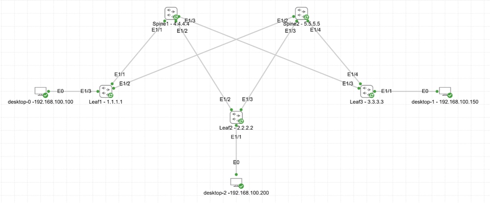 Network Connectivity Diagram
Configurations
Step 1.
- Enable feature Open Shortest Path First (OSPF).
- Add loopbacks to all device.
- Enable OSPF on Ethernet interfaces and loopbacks.
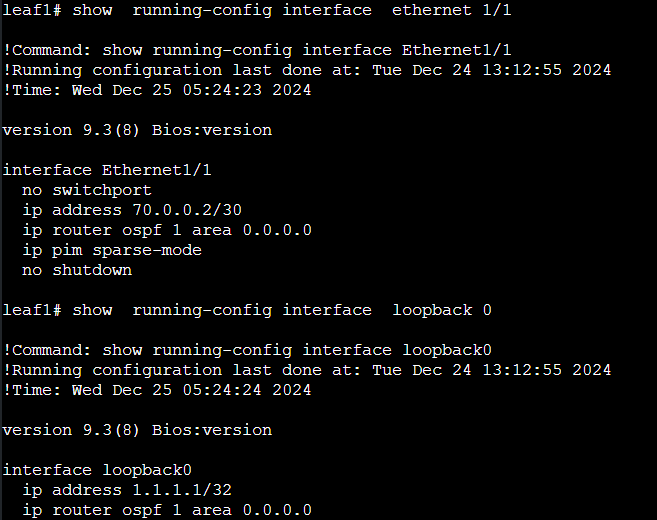 Enabling OSPF on Leaf Interface
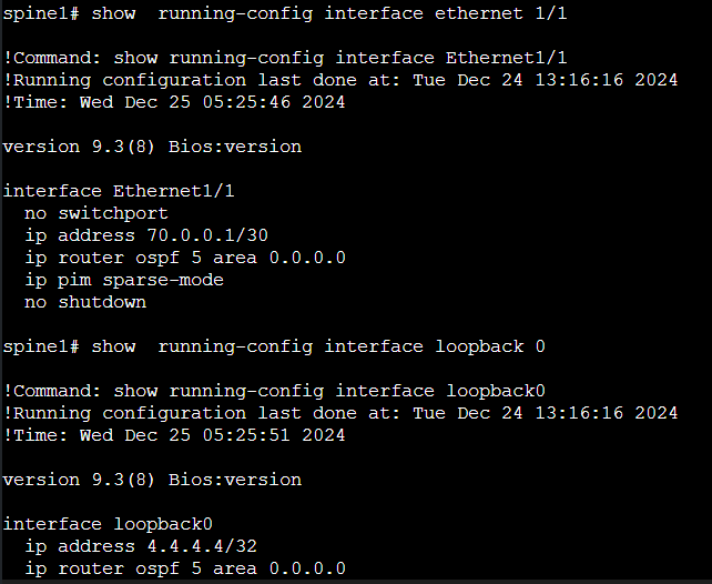 Enabling OSPF on Spine Interface
OSPF neighborship is established between Leaf and Spine switches.
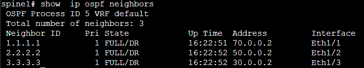 OSPF neighbor established with Leaf Switches
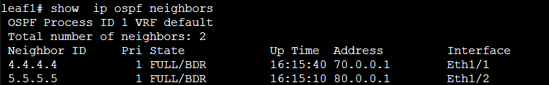 OSPF neighbor established with Spine Switches
 Ping reachability from Leaf1 to Leaf3
Step 2.
Add an additional loopback interface that is used for VXLAN on the leaf switches. Also, verify the reachability from all the leaf switches into the fabric.
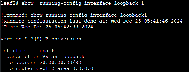 Loopback for VXLAN
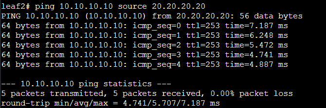 Overlay reachability from Leaf2 to Leaf1
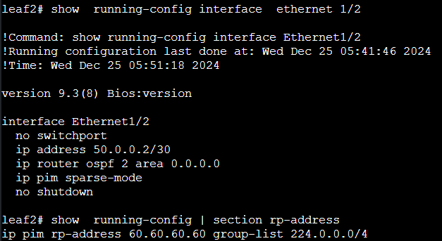
Step 3.
Configure PIM Any-Source Multicast (ASM) and Anycast RP on the spines:
- Enable the PIM feature.
- Enable PIM on all the underlay links.
- Create new loopback on spines to be used for Anycast RP.
- Advertise this loopback into OSPF.
- Configure Anycast RP (Nexus feature) on spines.
- Configure the RP on all devices.
ANYCAST RP:
Anycast RP is a mechanism for providing rapid RP failover and RP load-sharing. Anycast RP involves using the same IP address (rp-address) on two or more routers that functions as the RP. This IP address must be advertised in the Interior Gateway Protocol (IGP) so that other routers can choose the best path to the rp-address. In the event of a failure, the convergence time is the same as the IGP.
Having multiple RPs with the same IP address ensures that sources and receivers are always routed to the nearest RP based on the unicast routing table. PIM Join messages from receivers can be sent to one RP, while PIM-designated routers register their local sources to another RP.
It is important to synchronize information between the different RPs because some senders and receivers can join router 1 as the RP, while others can join router 2 as the RP. If the routers do not have complete information about all the sources, multicast communication can be disrupted. In order to address this problem, a mechanism is required to synchronize information about sources among all the routers acting as an RP.
There are two protocols that can serve this purpose: Multicast Source Discovery Protocol (MSDP) and PIM.
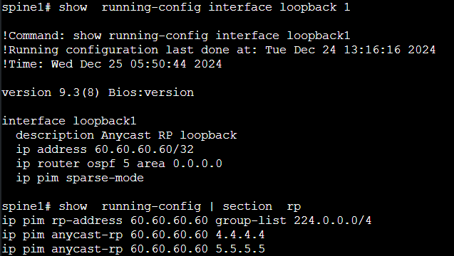 60.60.60.60 is the Anycast RP IP and 4.4.4.4/5.5.5.5 are the Loopback IP of Spine 1 and Spine 2
 Anycast RP configuration on Leaf Switches
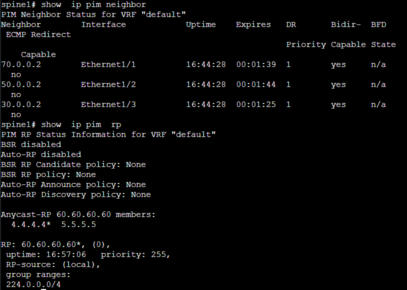 PIM neighborship formed

Note: Do not forget to also put PIM on the loopback to be used for VXLAN on leaf switches.
Step 4.
- Enable VXLAN feature.
- Enable feature in order to map VLANs to Virtual Network Identifiers (VNIs).
- Create NVE.
- Configure access port towards desktop.
 Enabling VXLAN Features
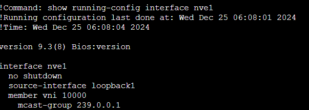 Creating NVE Interface
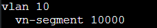 VLAN to VN Segment Mapping
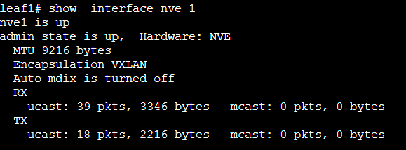 Status of NVE Interface
Initiate a ping from Desktop0 to Desktop1 and Desktop2 in order to verify their reachability.
When an Address Resolution Protocol (ARP) request is initiated from Desktop0 to Desktop1, the ARP packet is sent to Leaf1. Leaf1 then forwards the packet towards the Spine device using multicast address 239.0.0.1, which is used for VNI1000. The Spine device multicasts the packets to all the leaf devices that are part of the same VNI 10000.
Ping from Desktop0 (192.168.100.100) to Desktop1 (192.168.100.150) and Desktop2 (192.168.100.200).
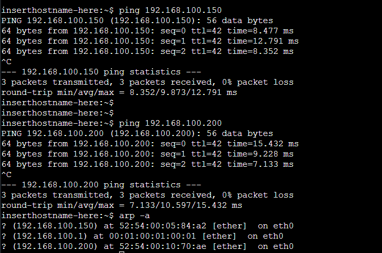 Ping from Desktop0 to Desktop1 and Desktop2
LEAF1 is forming NVE peer with LEAF3.
leaf1# show  nve  peers

Interface Peer-IP                                 State LearnType Uptime   Route

r-Mac

--------- --------------------------------------  ----- --------- -------- -----

------------

nve1      30.30.30.30                             Up    DP        00:10:23 n/a


leaf1# show  nve  vni 10000

Codes: CP - Control Plane        DP - Data Plane

       UC - Unconfigured         SA - Suppress ARP

       SU - Suppress Unknown Unicast

       Xconn - Crossconnect

       MS-IR - Multisite Ingress Replication


Interface VNI      Multicast-group   State Mode Type [BD/VRF]      Flags

--------- -------- ----------------- ----- ---- ------------------ -----

nve1      10000    239.0.0.1         Up    DP   L2 [10]
LEAF3 is forming NVE peer with LEAF1.
leaf3# show  nve  peers

Interface Peer-IP                                 State LearnType Uptime   Route

r-Mac

--------- --------------------------------------  ----- --------- -------- -----

------------

nve1      10.10.10.10                             Up    DP        00:10:56 n/a


leaf3# show  nve vni 10000

Codes: CP - Control Plane        DP - Data Plane

       UC - Unconfigured         SA - Suppress ARP

       SU - Suppress Unknown Unicast

       Xconn - Crossconnect

       MS-IR - Multisite Ingress Replication


Interface VNI      Multicast-group   State Mode Type [BD/VRF]      Flags

--------- -------- ----------------- ----- ---- ------------------ -----

nve1      10000    239.0.0.1         Up    DP   L2 [10]


leaf1# show  mac address-table

Legend:

        * - primary entry, G - Gateway MAC, (R) - Routed MAC, O - Overlay MAC

        age - seconds since last seen,+ - primary entry using vPC Peer-Link,

        (T) - True, (F) - False, C - ControlPlane MAC, ~ - vsan

   VLAN     MAC Address      Type      age     Secure NTFY Ports

---------+-----------------+--------+---------+------+----+------------------

*   10     5254.0004.8b92   dynamic  0         F      F    Eth1/3                                      ------- MAC Address of Desktop0 connected to Leaf1

*   10     5254.0005.84a2   dynamic  0         F      F    nve1(30.30.30.30)                    ------- MAC Address of Desktop1 connected to Leaf3

G    -     5206.ab8a.1b08   static   -         F      F    sup-eth1(R)


leaf3# show  mac address-table

Legend:

        * - primary entry, G - Gateway MAC, (R) - Routed MAC, O - Overlay MAC

        age - seconds since last seen,+ - primary entry using vPC Peer-Link,

        (T) - True, (F) - False, C - ControlPlane MAC, ~ - vsan

   VLAN     MAC Address      Type      age     Secure NTFY Ports

---------+-----------------+--------+---------+------+----+------------------

*   10     5254.0004.8b92   dynamic  0         F      F    nve1(10.10.10.10)                 ------- MAC Address of Desktop0 connected to Leaf1

*   10     5254.0005.84a2   dynamic  0         F      F    Eth1/1                                    ------- MAC Address of Desktop1 connected to Leaf3

G    -     5206.0619.1b08   static   -         F      F    sup-eth1(R)
Here is the Wireshark snapshot when an ARP packet is initiated from Leaf1 to a multicast.
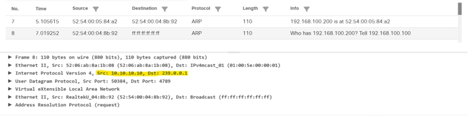 Wireshark Capture showing ARP request packet going to multicast group
 Feedback