Introduction
This document describes how to configure a dual ISP topology with two hubs and four spokes in the same region using the SD-WAN wizard.
Prerequisites
Requirements
Cisco recommends that you have knowledge of these topics:
- Cisco Secure Firewall Threat Defense (FTD)
- Cisco Secure Firewall Management Center (FMC)
- Software-defined WAN (SD-WAN)
Components Used
The information in this document is based on these software and hardware versions:
- FTD version 7.6.0
- FMC version 7.6.0
The information in this document was created from the devices in a specific lab environment. All of the devices used in this document started with a cleared (default) configuration. If your network is live, ensure that you understand the potential impact of any command.
Background information
Supported Software & Hardware Platforms
|
Manager
|
FTD
|
Supported Platforms
|
|
|
-
Hub FTD >= 7.6.0
-
Spoke FTD >= 7.3.0
|
All platforms that FMC >= 7.6.0 can manage
|
Configure
Network Diagram
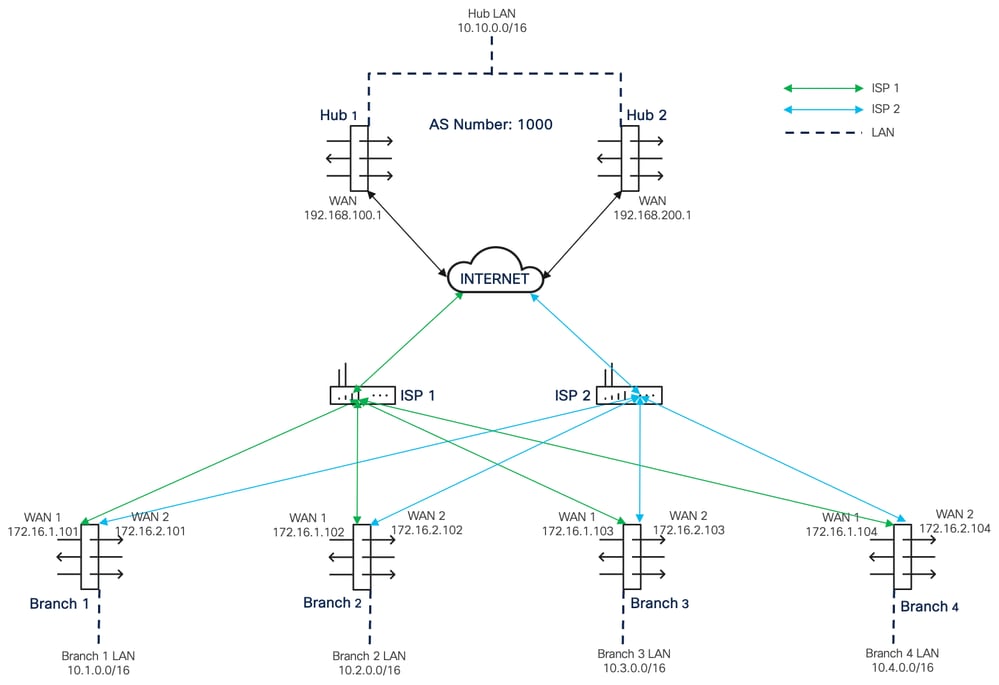 Network topology diagram
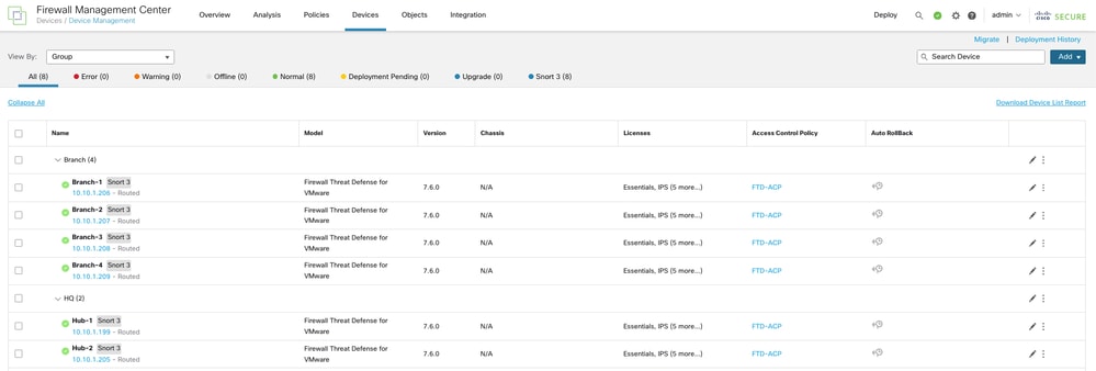 List of devices
Step 1. Create an SD-WAN Topology with WAN-1 as the VPN Interface
Navigate to Devices > VPN > Site To Site. Choose Add, and enter a suitable name in the Topology Name field for the first topology with WAN-1 as the VPN interface. Click SD-WAN Topology>Create.
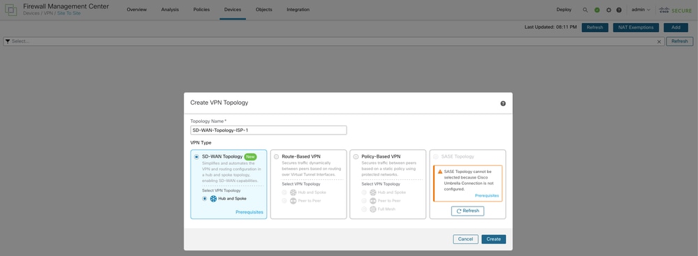 Create an SD-WAN Topology with WAN-1 as the VPN Interface
Step 2. Configure the Dynamic Virtual Tunnel Interface (DVTI) on the Primary Hub
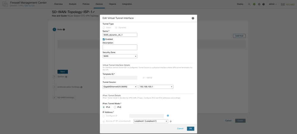
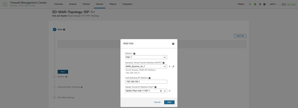
Click Add Hub and choose the primary hub from the Device drop-down list. Click the + icon next to Dynamic Virtual Tunnel Interface (DVTI). Configure a name, security zone, and template ID and assign WAN-1 as the Tunnel Source interface for the DVTI.
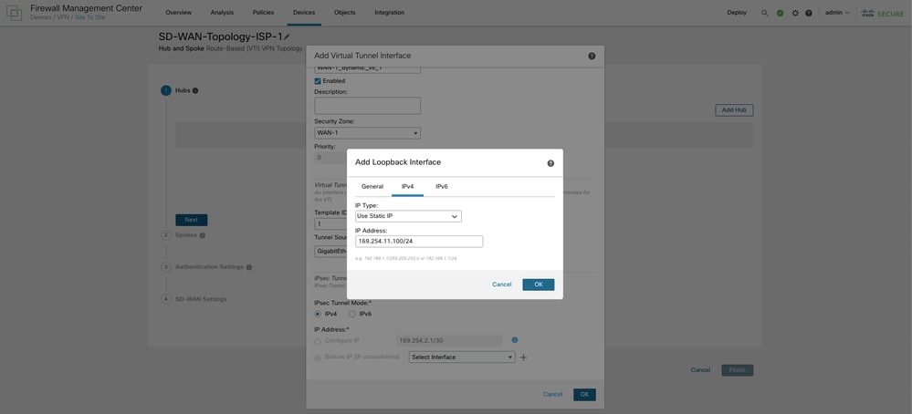
Choose a physical or loopback interface from the Borrow IP drop-down list. In the current topology, the DVTI inherits a loopback interface IP address. Click OK.
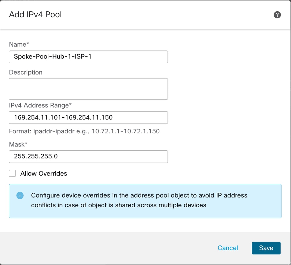
Choose an address pool or click the + icon next to Spoke Tunnel IP Address Pool in order to create a new address pool. When you add spokes, the wizard auto generates spoke tunnel interfaces, and assigns IP addresses to these spoke interfaces from this IP address pool.
Once the primary hub configuration is complete, choose Add in order to save the primary hub in the topology.
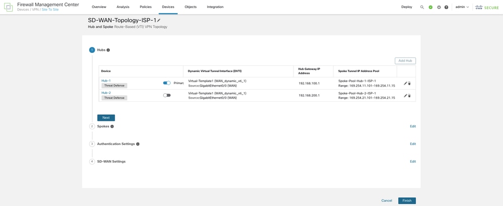
Step 3. Configure the DVTI on the Secondary Hub
Now choose Add Hub again in order to configure the secondary hub in the topology with WAN-1 as the VPN interface by repeating steps 1 and 2. Click Next.
Step 4. Configure the Spokes
Choose Add Spoke in order to add a single spoke device, or click Add Spokes (Bulk Addition) in order to add multiple spokes to your topology. The current topology uses the latter option in order to add multiple branch FTDs to the topology. In the Add Bulk Spokes dialog box, choose the required FTDs in order to add them as spokes. Choose either a common Interface Name Pattern that matches the logical name of WAN-1 on all spokes or the Security Zone that is associated with WAN-1.
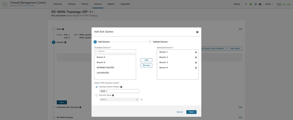
Click Next so that the wizard validates if the spokes have interfaces with the specified pattern or security zone.
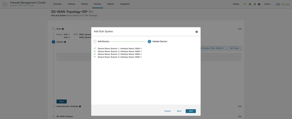
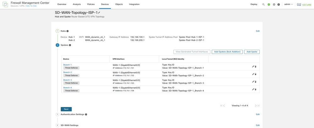
Choose Add and the wizard automatically chooses the hub DVTI as the tunnel source IP address for each spoke.
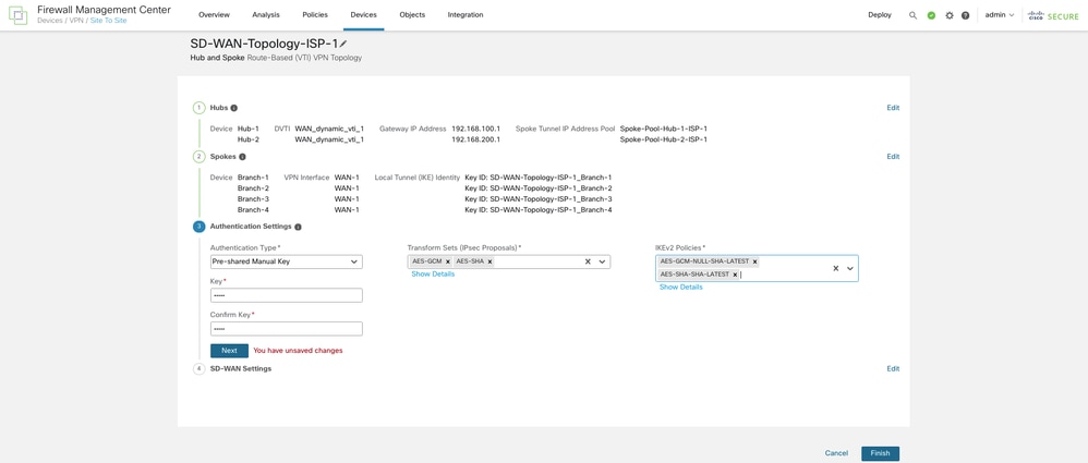
Step 5. Configure the Authentication Settings
Click Next in order to configure the Authentication Settings. For device authentication, you can choose a manual pre-shared key, an auto-generated pre-shared key, or a certificate in the Authentication Type drop-down list. Choose one or more algorithms from the Transform Sets and IKEv2 Policies drop-down lists.
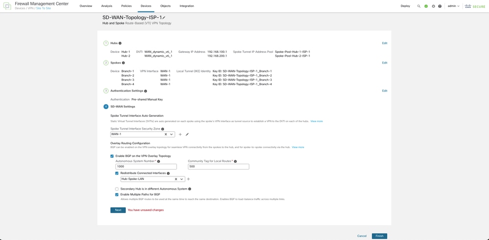
Step 6. Configure the SD-WAN Settings
Click Next in order to configure the SD-WAN Settings. This step involves the auto-generation of spoke tunnel interfaces, and Border Gateway Protocol (BGP) configuration of the overlay network. From the Spoke Tunnel Interface Security Zone drop-down list, choose a security zone or click + in order to create a security zone to which the wizard automatically adds the spokes' auto-generated Static Virtual Tunnel Interfaces (SVTIs).
Check the Enable BGP on the VPN Overlay Topology check box in order to automate BGP configurations between the overlay tunnel interface. In the Autonomous System Number field, enter an Autonomous System (AS) number. Check the Redistribute Connected Interfaces check box and choose an interface group from the drop-down list or choose + in order to create an interface group with connected LAN interfaces of the hubs and spokes for BGP route redistribution in the overlay topology.
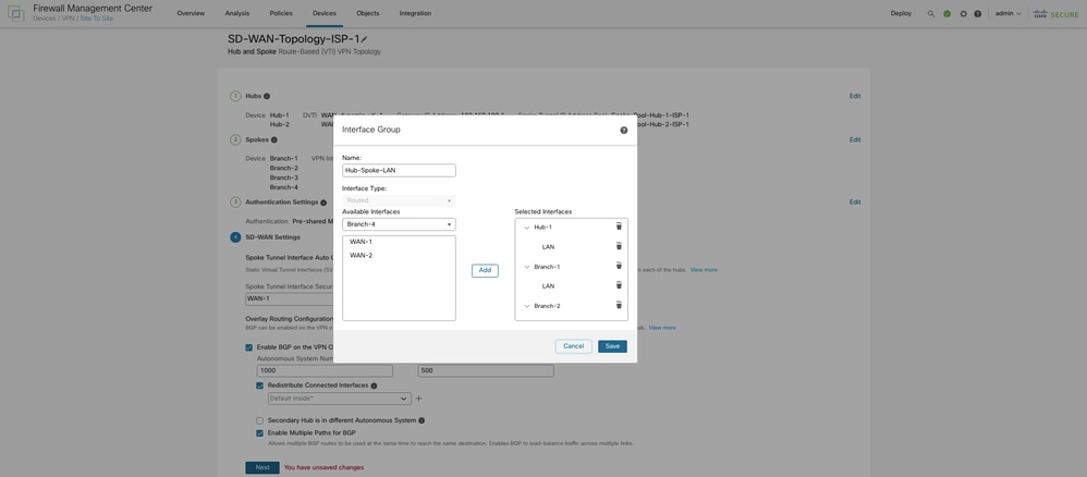
In the Community Tag for Local Routes field, enter the BGP community attribute in order to tag connected and redistributed local routes. This attribute enables easy route filtering. Check the Secondary Hub is in the Different Autonomous System check box if you have a secondary hub in a different AS. Finally, check the Enable Multiple Paths for BGP check box in order to enable BGP to load-balance traffic across multiple links.
Click Finish in order to save and validate the SD-WAN topology.
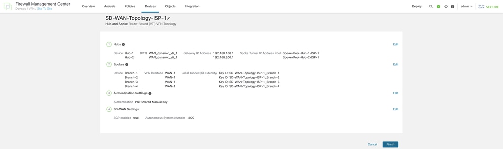
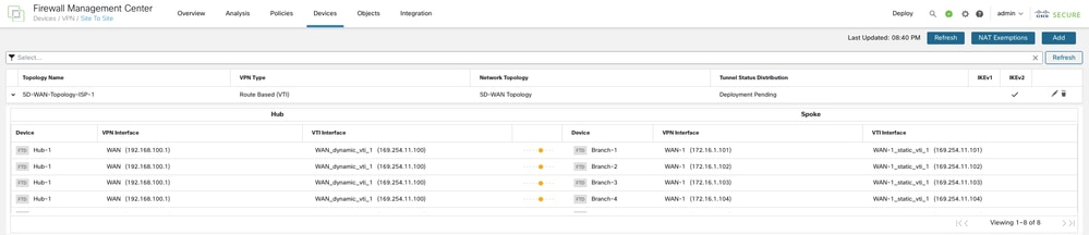
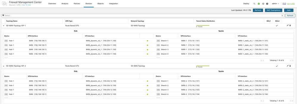
You can view the topology under Devices > Site-to-site VPN. The total number of tunnels in the first SD-WAN topology is 8.
Step 7. Create an SD-WAN Topology with WAN-2 as the VPN Interface
Repeat steps 1 through 6 in order to configure an SD-WAN Topology with WAN-2 as the VPN interface. The total number of tunnels in the second SD-WAN topology is 8. The final topologies must look like the image shown:

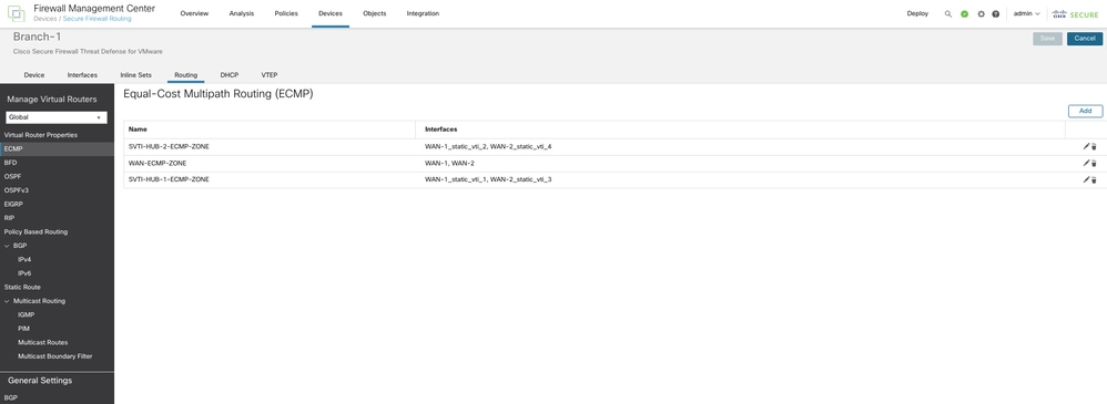
Step 8. Configure (Equal-Cost Multi-Path) ECMP Zones
On each branch, navigate to Routing > ECMP and configure ECMP Zones for the WAN interfaces and SVTIs connecting to both the primary and secondary Hub, as shown. This can provide link redundancy and enable load balancing of the VPN traffic.
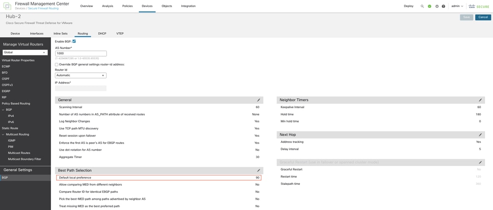
Step 9. Modify the BGP Local Preference on the Hub
Navigate to Routing > General Settings > BGP on the secondary hub. Click Enable BGP, configure the AS Number, and set the default local preference value under Best Path Selection to a value lower than the one configured on the primary hub. Click Save. This ensures that routes to the primary hub are preferred over routes to the secondary hub. When the primary hub goes down, the routes to the secondary hub take over.
Deploy the configurations to all the devices.
Verify
Verify Tunnel Statuses
In order to verify if the VPN tunnels of the SD-WAN topologies are up, navigate to Device > VPN > Site-to-Site.
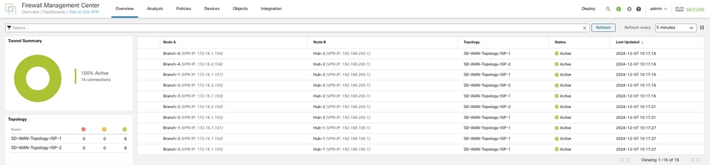
In order to view details of the SD-WAN VPN tunnels, choose Overview > Dashboards > Site-to-site VPN.
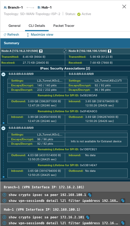
In order to view more details of each VPN tunnel:
- Hover over a tunnel.
- Click the View Full Information (
 ) icon. A pane with tunnel details and more actions appears.
- Click the CLI Details tab in the side pane in order to view the show commands and details of the IPsec security associations.
Verify Virtual Tunnel Interfaces (VTIs)
In order to view the dynamic VTIs of hubs and static VTIs of spokes:
- Navigate to Devices > Device Management.
- Choose the edit icon for a hub or a spoke device.
- Click the Interface tab.
- Click the Virtual Tunnels tab.
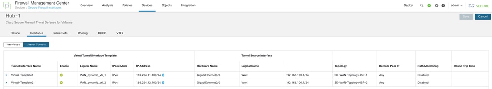
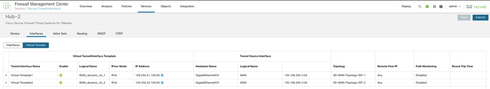
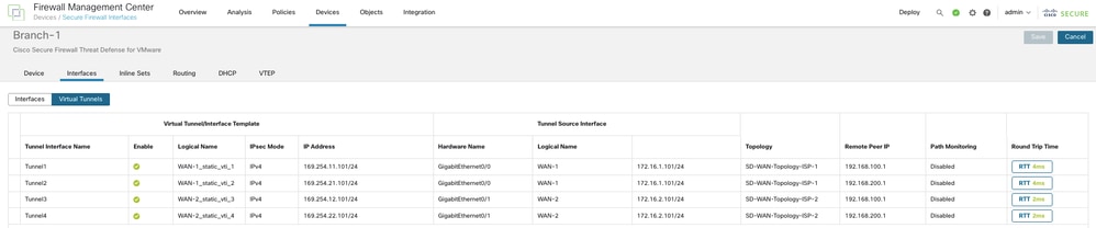
For each VTI, you can view details such as name, IP address, IPsec mode, tunnel source interface details, topology, and remote peer IP.
DVTIs on the primary hub:
DVTIs on the secondary hub:
SVTIs on the spoke:
In order to verify load-balancing, dual ISP redundancy, and hub level redundancy, only traffic from Branch 1 to the Hub is used. The details of the setup are shown here:
10.1.0.0.100 - Client in Branch 1 connected network
10.10.0.0.100 - Client in Hub connected network
WAN-1_static_vti_1 - SVTI to Hub 1 via ISP 1
WAN-2_static_vti_3 - SVTI to Hub 1 via ISP 2
WAN-1_static_vti_2 - SVTI to Hub 2 via ISP 1
WAN-2_static_vti_4 - SVTI to Hub 2 via ISP 2
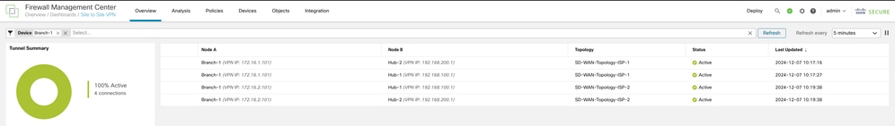
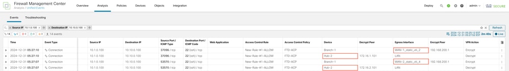
Verify Load Balancing of VPN Traffic
The tunnel status can be seen in the Site to Site VPN dashboard. Ideally, all tunnels must be active:
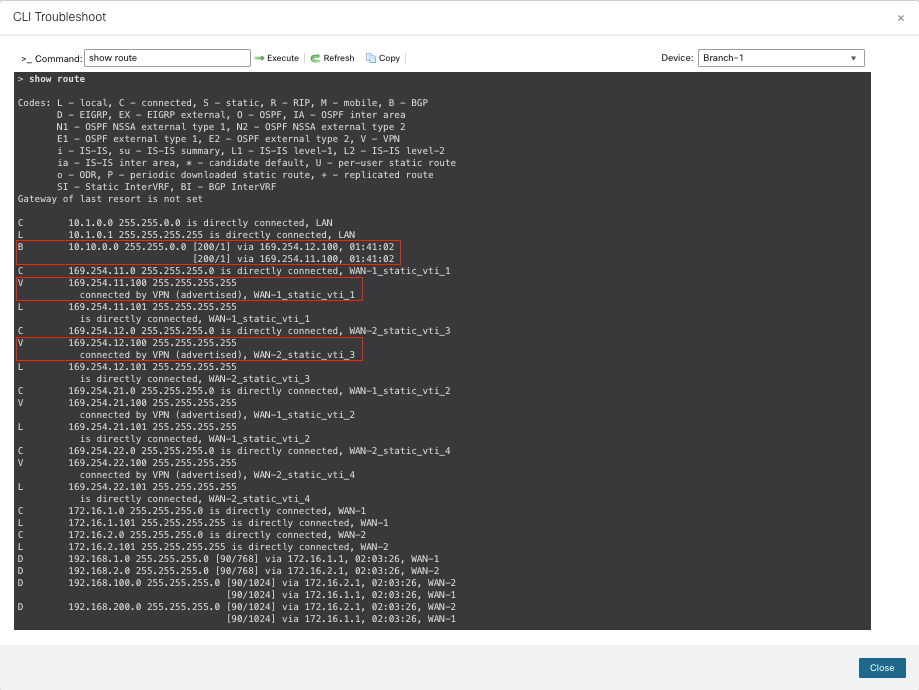
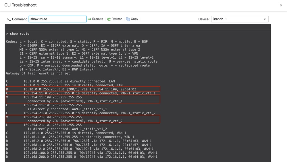
Routes to the primary hub are preferred. The show route command on Branch 1 indicates that the VPN traffic is load-balanced between the two SVTIs on ISP 1 and ISP 2 to the primary hub:
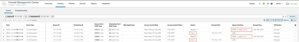
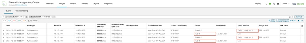
The Egress Interface taken for the actual VPN traffic can be seen in Unified Events:
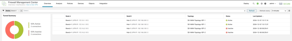
Verify Dual ISP Redundancy
When ISP-2 is down, the tunnel status indicates that the tunnels via ISP-1 are active:
Routes to the primary hub are preferred. The show route command on Branch 1 indicates that the VPN traffic is routed via the SVTIs on ISP-1 to the primary hub:
The Egress Interface taken for the actual VPN traffic can be seen in Unified Events:
Verify Hub Level Redundancy
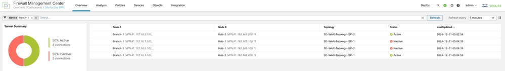
When the primary hub is down, the tunnel status indicates that the tunnels to the secondary hub are active:
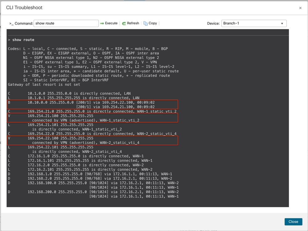
Since the primary hub is down, the routes to the secondary hub are preferred. The show route command on Branch 1 indicates that the VPN traffic is load-balanced between the two SVTIs on ISP 1 and ISP 2 to the secondary hub:
The Egress Interface taken for the actual VPN traffic can be seen in Unified Events:
 Feedback