Introduction
This document describes the steps to configure a cdFMC managed virtual FTD to use the redundant manager access data interface feature.
Prerequisites
Requirements
Cisco recommends that you have knowledge of these topics:
- Cisco Secure Firewall Management Center
- Cisco Defense Orchestrator
Components Used
The information in this document is based on these software and hardware versions:
- Cloud delivered Firewall Management Center
- Virtual Secure Firewall Threat Defense version 7.3.1 hosted in Azure Cloud.
The information in this document was created from the devices in a specific lab environment. All of the devices used in this document started with a cleared (default) configuration. If your network is live, ensure that you understand the potential impact of any command.
Related Products
This document can also be used with these hardware and software versions:
- Any physical appliance capable of running Firepower Threat Defense version 7.3.0 or higher.
Background Information
This document shows the steps to configure and verify a cdFMC managed vFTD to use two data interfaces for management purposes. This feature is often useful when customers need a second data-interface to manage their FTD over the Internet, using a second ISP. By default, the FTD does a round-robin load balancing for the management traffic between both interfaces; this can be modified to an Active/Backup deployment as is described in this document.
Redundant data-interface for management feature was introduced in Secure Firewall Threat Defense version 7.3.0. Assumption is given that the vFTD has reachability to a name server that can resolve URLs for CDO access.
Configuration
Network Diagram
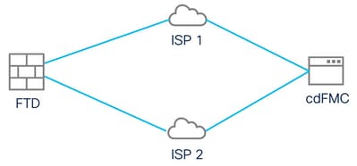 Network Diagram
Configure a Data Interface For Management Access
Log into the device via the console and configure one of the data interfaces for management access with the command configure network management-data-interface:
> configure network management-data-interface

Note: The Management default route will be changed to route through the data interfaces. If you are connected to the Management
interface with SSH, your connection may drop. You must reconnect using the console port.

Data interface to use for management: GigabitEthernet0/0
Specify a name for the interface [outside]: outside-1
IP address (manual / dhcp) [dhcp]: manual
IPv4/IPv6 address: 10.6.2.4
Netmask/IPv6 Prefix: 255.255.255.0
Default Gateway: 10.6.2.1
Keep in mind that the original management interface cannot be configured to use DHCP. You can use the command show network to verify this.
Onboard the FTD with CDO
This process onboards the Azure FTD with CDO so it can be managed by a cloud-delivered FMC. The process uses a CLI registration key, which is beneficial if your device has a IP address assigned via DHCP. Other onboarding methods like log-touch provisioning and serial number are only supported on Firepower 1000, Firepower 2100, or Secure Firewall 3100 platforms.
Step 1. In the CDO portal navigate to Inventory and then click Onboard option:
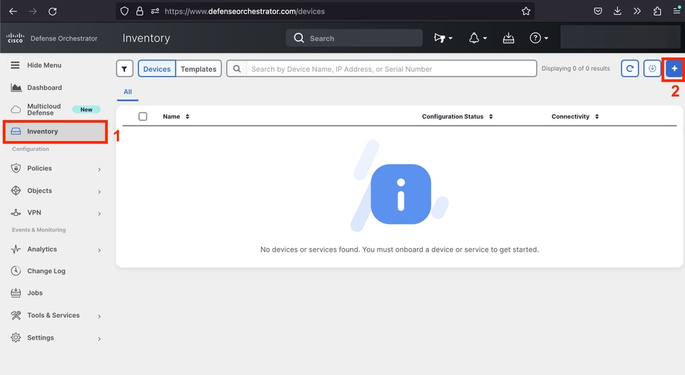 Inventory Page
Step 2. Click in the FTD tile:
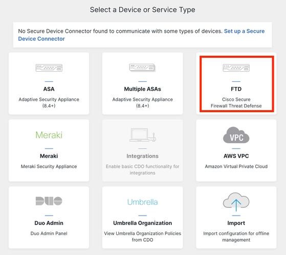 Onboarding the FTD
Step 3. Choose the option Use CLI Registration key:
 Use the CLI Registration Key
Step 4. Copy the CLI Key starting from configure manager command:
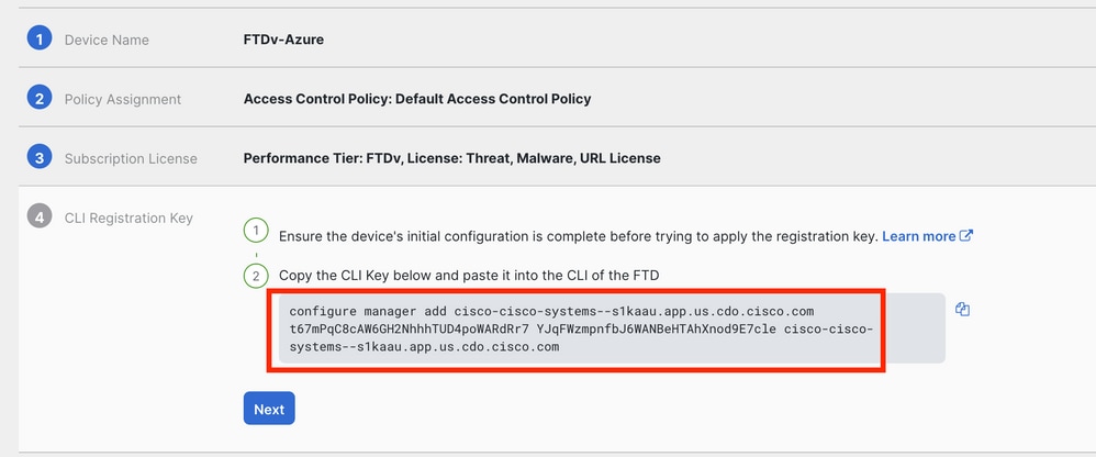 Copy Configure Manager Command

Note: The CLI key matchess the format used in registrations of FTDs with on-prem FMCs where you can configure a NAT-ID to allow the registration when your managed device is behind a NAT device: configure manager add <fmc-hostname-or-ipv4> <registration-key> <nat-id> <display-name>
Step 5. Paste the command in the FTD CLI. You must receive this message if the communication was successful:
Manager cisco-cisco-systems--s1kaau.app.us.cdo.cisco.com successfully configured.
Please make note of reg_key as this will be required while adding Device in FMC.
Step 6. Go back to the CDO and click in Next:
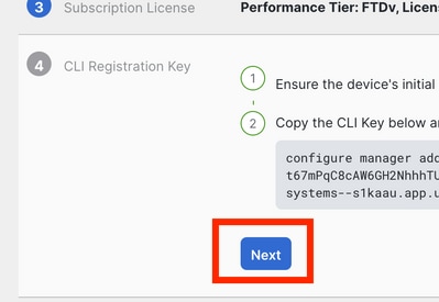 Click Next
CDO continues the enrolling process and a message is displayed mentioning that it is going to take a long time to be completed. You can check the status of the enrollment process by clicking in the Devices link in the Services page.
Step 7. Access your FMC through the Tools & Services page.
 Accessing the cdFMC
Click in Devices link.
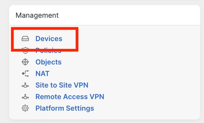 Click Devices
Your FTD is now onboarded in CDO and can be managed by the cloud-delivered FMC. Notice in next image that there is a NO-IP listed under the device name. This is expected in a onboarding process using CLI registration key.
 Managed FTD
Configure a Redundant Data Interface for Manager Access
This process assigns a second data interface for management access.
Step 1. In the Devices tab, click in the pencil icon to access the FTD edit mode:
 Edit the FTD
Step 2. From the Interface tab, edit the interface that is going to be assigned as the redundant management interface. If this was not done previously, configure an interface name and an IP address.
Step 3. In the Manager Access tab enable the Enable management on this interface for the manager checkbox:
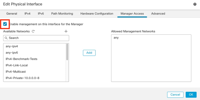 Enabling Manager Access
Step 4. In the General tab, ensure that the interface is assigned to a security zone and click OK:
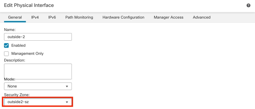 Security Zone for Redundant Data-Interface
Step 5. Notice that now both interfaces have the Manager Access tag. Additionally, ensure that the primary data-interface has a been assigned to a different Security Zone:
 Interface Config Review
In the next section, steps 6 through 10 are meant to configure two equal cost default routes to reach the CDO, each being monitored by an independent SLA tracking process. The SLA tracking ensures that there is a functional path to communicate with the cdFMC using the monitored interface.
Step 6. Navigate to the Routing tab and under ECMP menu create a new ECMP zone with both interfaces in it:
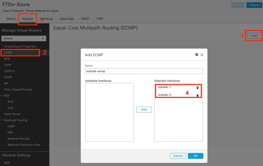 Configure an ECMP Zone
Click OK and Save.
Step 7. From the Routing tab, navigate to Static Routes.
Click in the pencil icon to edit your primary route. Then click the plus sign to add a new SLA tracking object:
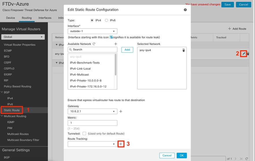 Edit Primary Route to Add the SLA Tracking
Step 8. Required parameters for a functional SLA tracking are highlighted in the next image. Optionally, you could tune other settings like Number of Packets, Timeout, and Frequency.
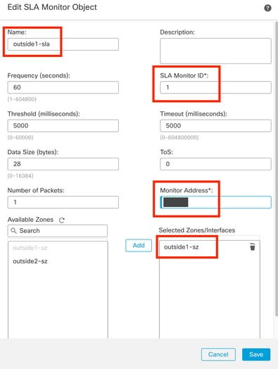 Configure SLA Tracking for ISP 1
In this example Google DNS IP was used to monitor FTD capabilities to reach Internet (and CDO) via the outside1 interface. Click ok when ready.

Note: Ensure that you are tracking an IP that has already been verified as reachable from your FTD outside interface. Configuring a track with an unreachable IP can bring the default route down in this FTD, and then preventing its ability to communicate with CDO.
Step 9. Click Save and make sure that the new SLA tracking is assigned to the route pointing to the primary interface:
 Outside 1 SLA Tracking
Once you click OK, a pop up is displayed with the next WARNING message:
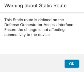 Config Warning
Step 10. Click Add Route option to add a new route for the redundant data-interface. Notice from the next image that the Metric value for the route is the same; additionally, the SLA tracking has a different ID:
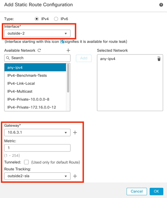 Configure Redundant Static Route
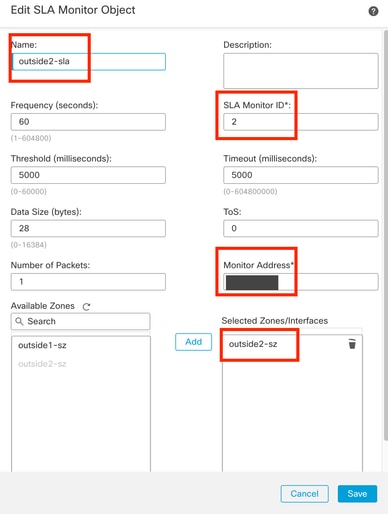 Configure Tracking for Redundant Data-Interface
Click Save.
Step 11. Optionally, you can specify the secondary data-interface IP under Device > Management. Even though, this is not required given that current onboarding method used the CLI registration key process:
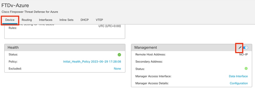 (Optional) Specify an IP for Redundant data-interface in the Management Field
Step 12. Deploy the changes.
(Optional) Set a Interface Cost for an Active/Backup Interface Mode:
By default, redundant management over data-interface uses round robin to distribute the management traffic between both interfaces. Alternatively, if one WAN link has higher bandwidth than the other and you prefer this to be the primary management link while the other remains as a backup, you can give the primary link a cost of 1 and give the backup link a cost of 2. In the next example, interface GigabitEthernet0/0 is kept as the primary WAN link while GigabiEthernet0/1 is serving as the backup management link:
1. Navigate to Devices > FlexConfig link and create a flexConfig policy. In case there is already a flexConfig policy configured and assigned to your FTD, edit it:
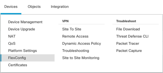 Accessing FlexConfig Menu
2. Create a new FlexConfig Object:
- Give a name to the FlexConfig object.
- Choose Everytime and Append in the Deployment and Type sections respectively.
- Set the cost for the interfaces with the next commands as depicted in the Image 22.
- Click Save.
interface GigabitEthernet0/0
  policy-route cost 1             <=== A cost of 1 means this will be the primary interface for management communication with CDO tenant.
interface GigabitEthernet0/1
  policy-route cost 2             <=== Cost 2 sets this interface as a backup interface.
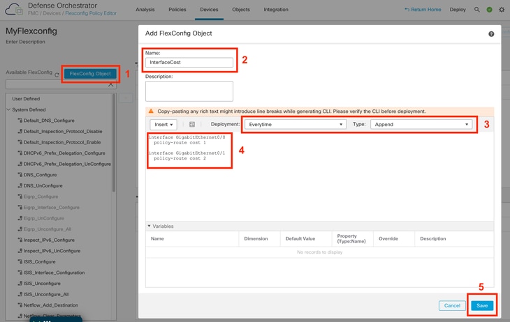 Adding a Flexconfig Object
3. Choose the recently created object and add it to the Sellected Append FlexConfigs section as depicted in the picture. Save the changes and deploy your configuration.
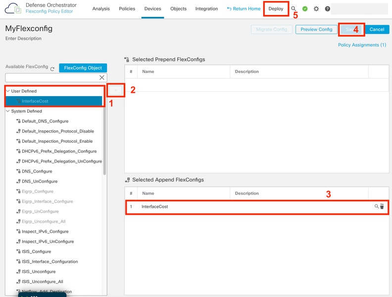 Assigning the Object to the Flexconfig Policy
4. Deploy the changes.
Verify
1. To verify, use the command show network. A new instance for the redundant management interface is formed:
> show network

<<---------- output omitted for brevity ---------->>

======================[ eth0 ]======================
State : Enabled
Link : Up
Channels : Management & Events
Mode : Non-Autonegotiation
MDI/MDIX : Auto/MDIX
MTU : 1500
MAC Address : 60:45:BD:D8:62:D7
----------------------[ IPv4 ]----------------------
Configuration : Manual
Address : 10.6.0.4
Netmask : 255.255.255.0
----------------------[ IPv6 ]----------------------
Configuration : Disabled

===============[ Proxy Information ]================
State : Disabled
Authentication : Disabled
. . .

===============[ GigabitEthernet0/0 ]===============
State : Enabled
Link : Up
Name : outside-1
MTU : 1500
MAC Address : 60:45:BD:D8:6F:5C
----------------------[ IPv4 ]----------------------
Configuration : Manual
Address : 10.6.2.4
Netmask : 255.255.255.0
Gateway : 10.6.3.1
----------------------[ IPv6 ]----------------------
Configuration : Disabled

===============[ GigabitEthernet0/1 ]===============
State : Enabled
Link : Up
Name : outside-2
MTU : 1500
MAC Address : 60:45:BD:D8:67:CA
----------------------[ IPv4 ]----------------------
Configuration : Manual
Address : 10.6.3.4
Netmask : 255.255.255.0
Gateway : 10.6.3.1
----------------------[ IPv6 ]----------------------
Configuration : Disabled
2. The interface is now part of the sftunnel domain. You can confirm this with the show sftunnel interfaces and the show running-config sftunnel commands:
> show sftunnel interfaces
Physical Interface Name of the Interface
GigabitEthernet0/0 outside-1
GigabitEthernet0/1 outside-2

> show running-config sftunnel
sftunnel interface outside-2
sftunnel interface outside-1
sftunnel port 8305
sftunnel route-map FMC_GEN_19283746_RBD_DUAL_WAN_RMAP_91827346
3. A policy-based route is automatically spell out. If you did not specify an interface cost, the adaptive-interface option sets round robin processing to load balance the management traffic between both interfaces:
> show running-config route-map
!
route-map FMC_GEN_19283746_RBD_DUAL_WAN_RMAP_91827346 permit 5
 match ip address FMC_GEN_056473829_RBD_DUAL_WAN_ACL_165748392
 set adaptive-interface cost outside-1 outside-2

> show access-list FMC_GEN_056473829_RBD_DUAL_WAN_ACL_165748392
access-list FMC_GEN_056473829_RBD_DUAL_WAN_ACL_165748392; 1 elements; name hash: 0x8e8cb508
access-list FMC_GEN_056473829_RBD_DUAL_WAN_ACL_165748392 line 1 extended permit tcp any any eq 8305 (hitcnt=26) 0x9e36863c
4. Use the show running-config interface <interface> command to check the interface settings:
> show running-config interface GigabitEthernet 0/0
!
interface GigabitEthernet0/0
nameif outside-1
security-level 0
zone-member outside-ecmp
ip address 10.6.2.4 255.255.255.0
policy-route cost 1

> show running-config interface GigabitEthernet 0/1
!
interface GigabitEthernet0/1
nameif outside-2
security-level 0
zone-member outside-ecmp
ip address 10.6.3.4 255.255.255.0
policy-route cost 2
Some additional commands can be used to check the tracking of the configured routes:
> show track
Track 1
Response Time Reporter 2 reachability
Reachability is Up                    <============= Ensure reachability is up for the monitored interfaces.
2 changes, last change 09:45:00
Latest operation return code: OK
Latest RTT (millisecs) 10
Tracked by:
STATIC-IP-ROUTING 0
Track 2
Response Time Reporter 1 reachability
Reachability is Up                    <============= Ensure reachability is up for the monitored interfaces.
2 changes, last change 09:45:00
Latest operation return code: OK
Latest RTT (millisecs) 1
Tracked by:
STATIC-IP-ROUTING 0


> show route

Codes: L - local, C - connected, S - static, R - RIP, M - mobile, B - BGP
D - EIGRP, EX - EIGRP external, O - OSPF, IA - OSPF inter area
N1 - OSPF NSSA external type 1, N2 - OSPF NSSA external type 2
E1 - OSPF external type 1, E2 - OSPF external type 2, V - VPN
i - IS-IS, su - IS-IS summary, L1 - IS-IS level-1, L2 - IS-IS level-2
ia - IS-IS inter area, * - candidate default, U - per-user static route
o - ODR, P - periodic downloaded static route, + - replicated route
SI - Static InterVRF, BI - BGP InterVRF
Gateway of last resort is 10.6.3.1 to network 0.0.0.0

S* 0.0.0.0 0.0.0.0 [1/0] via 10.6.3.1, outside-2
                   [1/0] via 10.6.2.1, outside-1
C 10.6.2.0 255.255.255.0 is directly connected, outside-1
L 10.6.2.4 255.255.255.255 is directly connected, outside-1
C 10.6.3.0 255.255.255.0 is directly connected, outside-2
L 10.6.3.4 255.255.255.255 is directly connected, outside-2
Related Information


 Feedback