Introduction
This document describes a best practice for redundant connections between Cisco Catalyst Switches and Cisco Secure Firewalls on High Availability.
Prerequisites
Requirements
Cisco recommends that you have knowledge of these topics:
- Secure Firewall Threat Defense (FTD)
- Secure Firewall Management Center (FMC)
- Cisco IOS® XE
- Virtual Switching System (VSS)
- High Availability (HA)
Components Used
The information in this document is based on these software and hardware versions:
- Secure Firewall Threat Defense version 7.2.5.1
- Secure Firewall Manager Center version 7.2.5.1
- Cisco IOS XE version 16.12.08
The information in this document was created from the devices in a specific lab environment. All of the devices used in this document started with a cleared (default) configuration. If your network is live, ensure that you understand the potential impact of any command.
Configure
Network Diagram
There are users that believe a single connection link (port channel) between one logical Catalyst Switch (VSS or Stacked) towards a pair of HA FTDs suffices to have a full redundant solution in case one unit or link fails. This is a common misconception because a VSS or Stacked Switch setup acts as a single logical device. While at the same time, a pair of HA FTDs act as two different logical devices with one as Active and the other as Standby.
The next diagram is an invalid design in which a single Port-Channel is configured from the Switch set up towards the FTD HA pair:
 Invalid Design
The previous configuration is not valid because this port-channel acts as a single link connected to two different devices, causing network collisions, so the Spanning Tree Protocol (SPT) blocks connections from one of the FTDs.
The next diagram is a valid design in which two different Port-Channels are configured for each member of the Switch VSS or Stack.
 Valid Design
Configurations
Switch Configuration
Step 1. Configure port-channels with their respective Virtual Local Area Network (VLAN).
MXC.PS.A.06-3850-02#configure terminal
MXC.PS.A.06-3850-02(config)#interface GigabitEthernet 1/0/1
MXC.PS.A.06-3850-02(config-if)#shutdown
MXC.PS.A.06-3850-02(config-if)#switchport mode access
MXC.PS.A.06-3850-02(config-if)#switchport access vlan 300
% Access VLAN does not exist. Creating vlan 300
MXC.PS.A.06-3850-02(config-if)#channel-group 2 mode active
Creating a port-channel interface Port-channel 2
MXC.PS.A.06-3850-02(config-if)#no shutdown
MXC.PS.A.06-3850-02(config-if)#exit
!
MXC.PS.A.06-3850-02(config)#interface GigabitEthernet 2/0/1
MXC.PS.A.06-3850-02(config-if)#shutdown
MXC.PS.A.06-3850-02(config-if)#switchport mode access
MXC.PS.A.06-3850-02(config-if)#switchport access vlan 300
MXC.PS.A.06-3850-02(config-if)#channel-group 2 mode active
MXC.PS.A.06-3850-02(config-if)#exit
!
MXC.PS.A.06-3850-02(config)#interface GigabitEthernet 1/0/2
MXC.PS.A.06-3850-02(config-if)#shutdown
MXC.PS.A.06-3850-02(config-if)#switchport mode access
MXC.PS.A.06-3850-02(config-if)#switchport access vlan 300
MXC.PS.A.06-3850-02(config-if)#channel-group 3 mode active
Creating a port-channel interface Port-channel 3
MXC.PS.A.06-3850-02(config-if)#no shutdown
MXC.PS.A.06-3850-02(config-if)#exit
!
MXC.PS.A.06-3850-02(config)#interface GigabitEthernet 2/0/2
MXC.PS.A.06-3850-02(config-if)#shutdown
MXC.PS.A.06-3850-02(config-if)#switchport mode access
MXC.PS.A.06-3850-02(config-if)#switchport access vlan 300
MXC.PS.A.06-3850-02(config-if)#channel-group 3 mode active
Step 2. Configure a Switched Virtual Interface (SVI) IP address for the Port-Channel VLAN.
MXC.PS.A.06-3850-02(config-if)#exit
MXC.PS.A.06-3850-02(config)#interface VLAN 300
MXC.PS.A.06-3850-02(config-if)#ip address 10.8.4.31 255.255.255.0
MXC.PS.A.06-3850-02(config-if)#no shutdown
FTD HA Configuration
Step 1. Log into the FMC GUI.
 FMC Log In
Step 2. Navigate to Devices > Device Management.
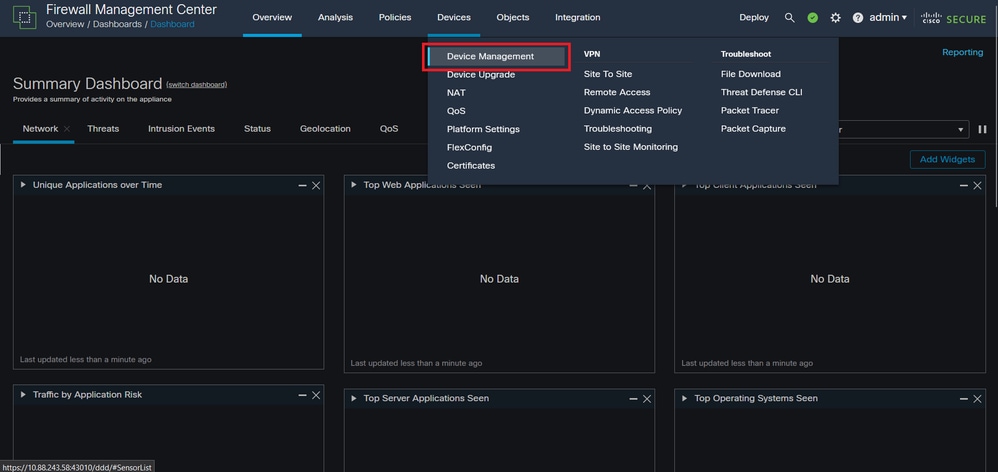 Device Management
Step 3. Edit the desired HA device and navigate to Interfaces > Add Interfaces > Ether Channel Interface.
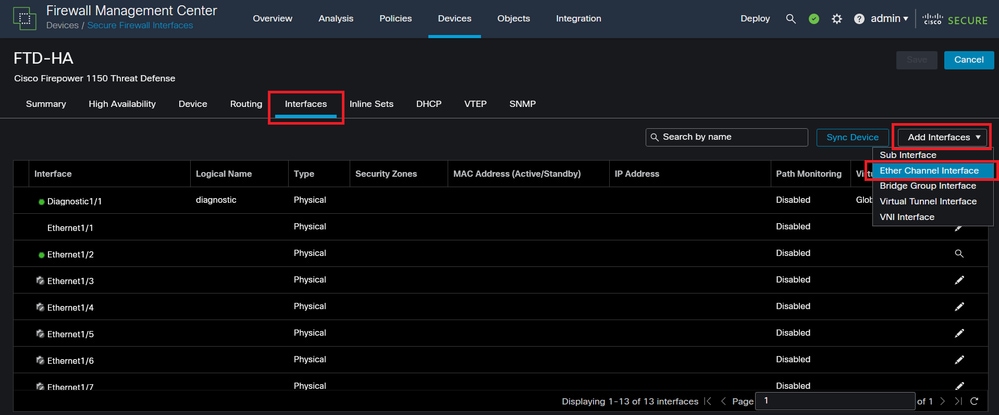 Ether-Channel Creation
Step 4. Add an interface name, Ether Channel ID, and the member interfaces.
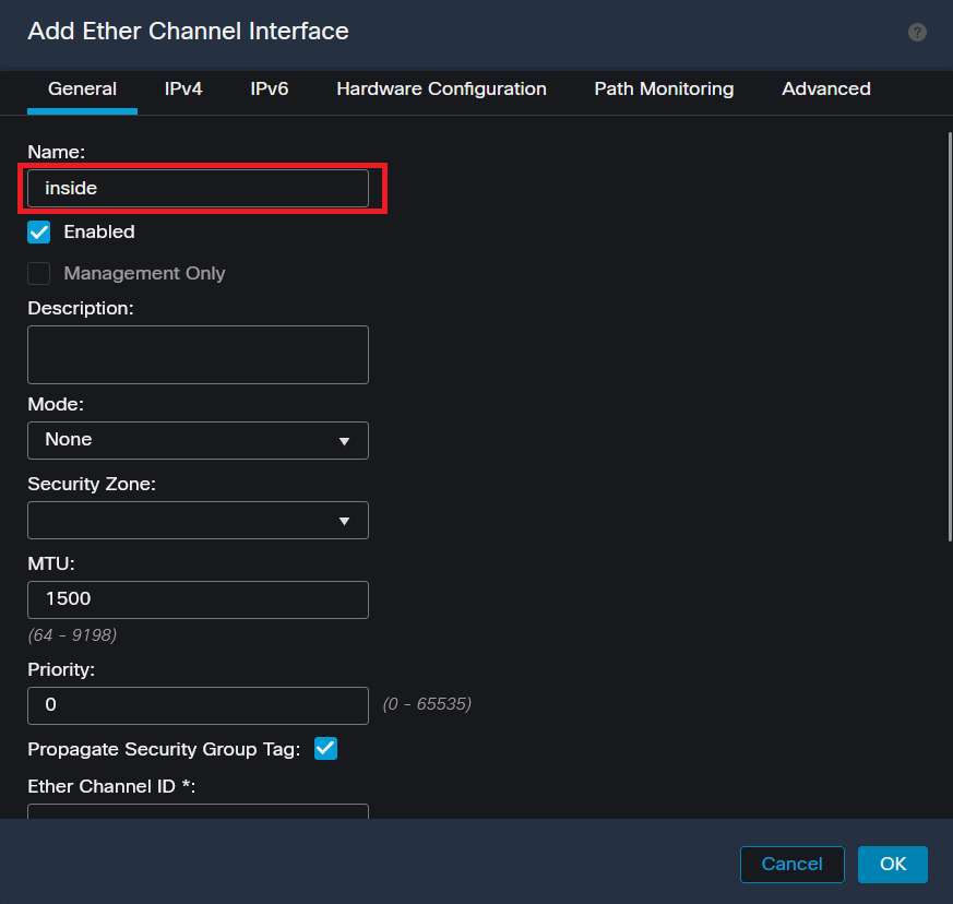 Ether-Channel Name
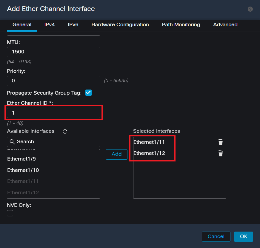 Ether-Channel ID and Members

Note: The Ether Channel ID on the FTD does not need to match the Port-Channel ID on the Switch.
Step 5. Navigate to the IPv4 tab and add an IP address on the same subnet as the VLAN 300 for the Switch.
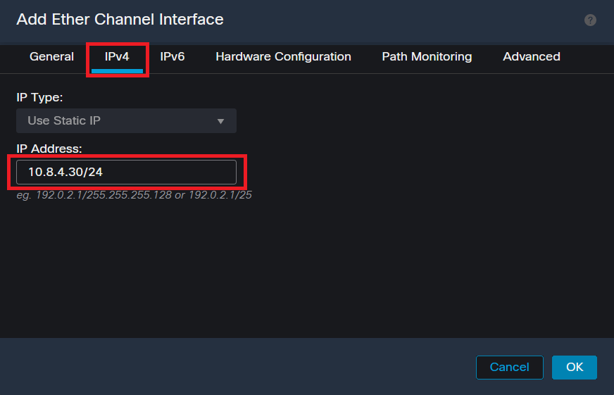 Ether-Channel IP Address
Step 6. Save the changes and Deploy.
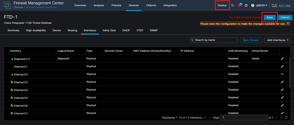 Save and Deploy
Verify
Step 1. Ensure the VLAN and port-channel interfaces Status is up from the Switch perspective.
MXC.PS.A.06-3850-02#show ip interface brief
Interface IP-Address OK? Method Status Protocol
***OUTPUT OMITTED FOR BREVITY***
Vlan300 10.8.4.31 YES manual up up
***OUTPUT OMITTED FOR BREVITY***
Port-channel2 unassigned YES unset up up
Port-channel3 unassigned YES unset up up
Step 2. Check that port-channel Status is up on both FTD units by accessing the device command line interface.
> system support diagnostic-cli
Attaching to Diagnostic CLI ... Press 'Ctrl+a then d' to detach.
Type help or '?' for a list of available commands.
firepower> en
Password:
firepower# show interface ip brief
***OUTPUT OMITTED FOR BREVITY***
Port-channel1 10.8.4.30 YES unset up up
***OUTPUT OMITTED FOR BREVITY***
Step 3. Check reachability between the Switch SVI and the FTD Port-Channel IP address.
MXC.PS.A.06-3850-02#ping 10.8.4.30 source vlan 300
Type escape sequence to abort.
Sending 5, 100-byte ICMP Echos to 10.8.4.34, timeout is 2 seconds:
Packet sent with a source address of 10.8.4.31
!!!!!
Success rate is 100 percent (5/5), round-trip min/avg/max = 1/1/2 ms


 Feedback