Configure ASA Active/Active Failover in Firepower 4100 Series
Available Languages
Download Options
Bias-Free Language
The documentation set for this product strives to use bias-free language. For the purposes of this documentation set, bias-free is defined as language that does not imply discrimination based on age, disability, gender, racial identity, ethnic identity, sexual orientation, socioeconomic status, and intersectionality. Exceptions may be present in the documentation due to language that is hardcoded in the user interfaces of the product software, language used based on RFP documentation, or language that is used by a referenced third-party product. Learn more about how Cisco is using Inclusive Language.
Contents
Introduction
This document describes how to configure Active/Active Failover in Cisco Firepower 4145 NGFW Appliance.
Prerequisites
Requirements
Cisco recommends that you have knowledge of this topic:
- Active/Standby failover in Cisco Adaptive Security Appliance (ASA).
Components Used
The information in this document is based on these software and hardware versions:
- Cisco Firepower 4145 NGFW Appliance (ASA) 9.18(3)56
- Firepower eXtensible Operating System (FXOS) 2.12(0.498)
- Windows 10
The information in this document was created from the devices in a specific lab environment. All of the devices used in this document started with a cleared (default) configuration. If your network is live, ensure that you understand the potential impact of any command.
Background Information
Active/Active failover is only available to security appliances that are running in multiple context mode. In this mode, the ASA is logically divided into multiple virtual devices, known as contexts. Each context operates as an independent device, with its own security policy, interfaces, and administrators.
The Active/Active failover is a feature of Adaptive Security Appliance (ASA) that allows two Firepower devices to pass the traffic simultaneously. This configuration is typically used for a load balancing scenario in which you want to split the traffic between two devices to maximize throughput. It is also used for redundancy purposes, so if one ASA fails, the other can take over without causing a disruption in service.
Mechanism of ASA Active/Active Failover
Each context in Active/Active failover is manually assigned to ether group 1 or group 2. The Admin context is assigned to group 1 by default. The same group (group1 or group2) in the two chassis (units) form a failover pair which is realizing the redundancy function. The behavior of each failover pair is basically same as the behavior in a Active/Standby failover. For more details about Active/Standby failover, please refer to Configure Active/Standby Failover. In Active/Active failover, in addition to the Role (Primary or Secondary) of each chassis, each group also has a Role (Primary or Secondary). These Roles are manually pre-set by the user and are used to decide the High Availability (HA) status (Active or Standby) for each failover group.
The Admin Context is a special context which is handling basic chassis management (such as SSH) connection. This is a image of Active/Active failover.
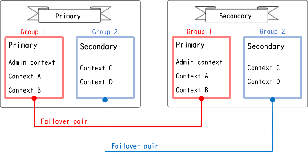 Failover Pair In Active/Active Failover
Traffic Flow
In Active/Active failover, traffic can be handled in the several patterns as shown in the next image.
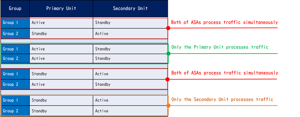 Traffic Flow
Traffic Flow Condition 1
- Primary Unit: Group 1 = Active, Group 2 = Standby
- Secondary Unit: Group 1 = Standby, Group 2 = Active
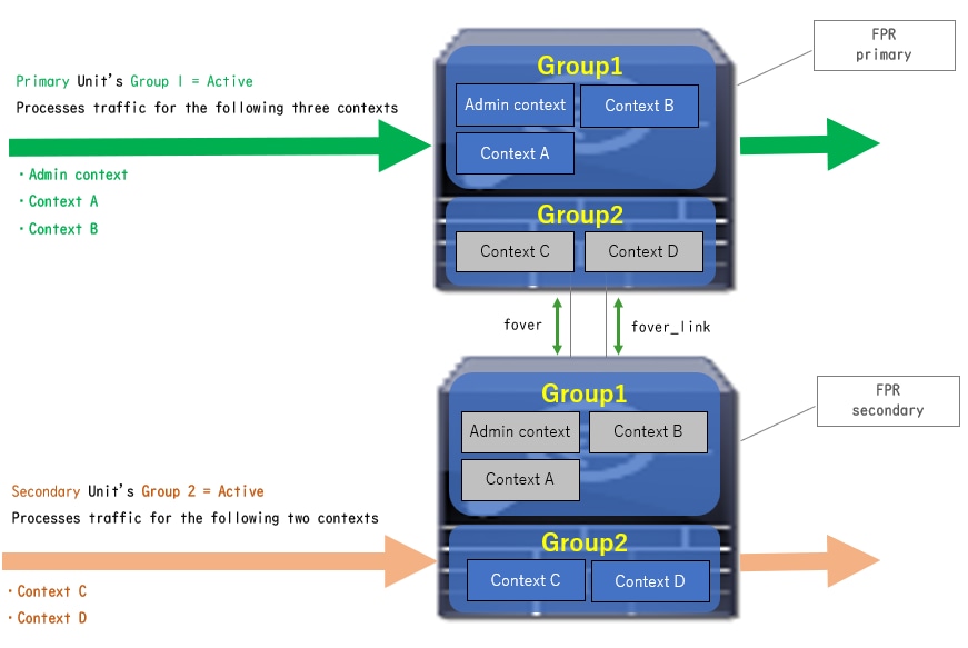 Traffic Flow Condition 1
Traffic Flow Condition 2
- Primary Unit: Group 1 = Active, Group 2 = Active
- Secondary Unit: Group 1 = Standby, Group 2 = Standby
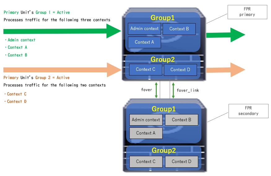 Traffic Flow Condition 2
Traffic Flow Condition 3
- Primary Unit: Group 1 = Standby, Group 2 = Active
- Secondary Unit: Group 1 = Active, Group 2 = Standby
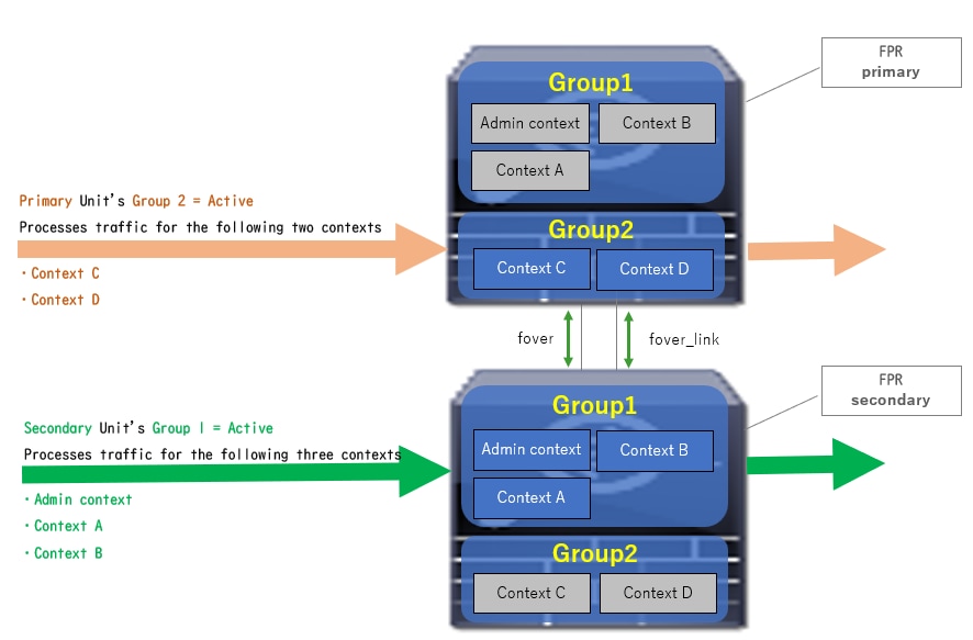 Traffic Flow Condition 3
Traffic Flow Condition 4
- Primary Unit: Group 1 = Standby, Group 2 = Standby
- Secondary Unit: Group 1 = Active, Group 2 = Active
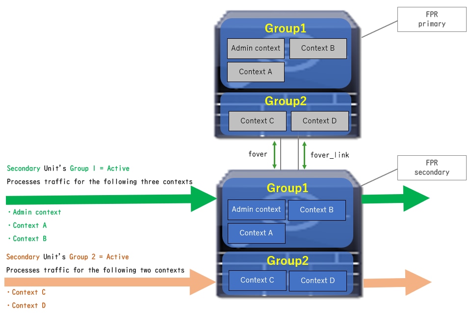 Traffic Flow Condition 4
Selection Rules for Active/Standby
In Active/Active failover , the status (active/standby) of each group is determined by these rules:
- Assume 2 devices are booting up almost at the same time, then one of the units (Primary or Secondary) becomes active firstly.
- When preempt time passed, the group which have same role in chassis and group becomes active.
- When there is a failover event (such as interface DOWN), the status of the group change in the same way as with Active/Standby failover.
- The preempt time does not work after doing manually failover.
This is an example of the status change.
- Both devices are booting up almost at the same time. Status A →
- Preempt time passed. Status B →
- Primary device failure (Failover is triggered). Status C →
- Preempt time passed since Primary device recovered from failure. Status D →
- Manually trigger failover. Status E
For details on Failover triggers and Health Monitoring, please refer to Failover Events.
1. Both devices are booting up almost at the same time.
 Status A
2. Preempt time (30s in this document) passed.
 Status B
3. Failure (such as Interface Down) occurred in group 1 of Primary unit.
 Status C
4. Preempt time (30s in this document) passed since group 1 of Primary device recoveried from failure.
 Status D
5. Manually setting group 2 of Primary Unit to Active.
 Status E
Network Diagram
This document introduce the configuration and verification for Active/Active failover base on this diagram.
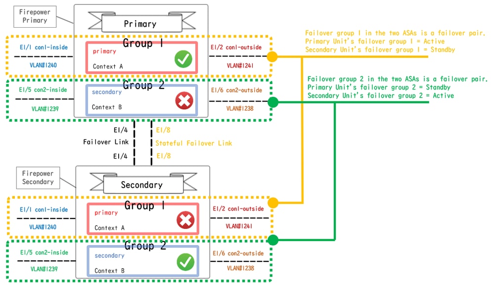 Logical Configuration Diagram
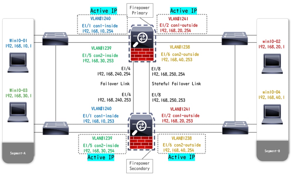 Physical Configuration Diagram
Configuration
Step 1. Pre-configure Interfaces
For both of Firepower, log in FCM GUI. Navigate to Logical Devices > Edit. Add data interface to ASA, as shown in the image.
 Pre-configure Interfaces
Step 2. Configuration on Primary Unit
Connect to the Primary FXOS CLI via SSH or console. Run connect module 1 console and connect asa command to enter into ASA CLI.
a. Configure failover on the Primary unit (run the command in the system context of the Primary unit).
failover lan unit primary
failover lan interface fover E1/4
failover link fover_link E1/8
failover interface ip fover 192.168.240.254 255.255.255.0 standby 192.168.240.253
failover interface ip fover_link 192.168.250.254 255.255.255.0 standby 192.168.250.253
failover group 1   <--- group 1 is assigned to primary by default
preempt 30
failover group 2
secondary
preempt 30
failover
prompt hostname state priority context
b. Configure failover group for context (run the command in the system context of the Primary unit).
admin-context admin
context admin         <--- admin context is assigned to group 1 by default
allocate-interface E1/3
config-url disk0:/admin.cfg

context con1
allocate-interface E1/1
allocate-interface E1/2
config-url disk0:/con1.cfg
join-failover-group 1 <--- add con1 context to group 1
!
context con2
allocate-interface E1/5
allocate-interface E1/6
config-url disk0:/con2.cfg
join-failover-group 2 <--- add con2 context to group 2
c. Run changeto context con1 to connect con1 context from system context . Configure IP for Interface of the con1 context (run the command in con1 context of Primary unit).
interface E1/1
nameif con1-inside
ip address 192.168.10.254 255.255.255.0 standby 192.168.10.253
security-level 100
no shutdown
interface E1/2
nameif con1-outside
ip address 192.168.20.254 255.255.255.0 standby 192.168.20.253
no shutdown
d. Run changeto context con2 to connect con2 context from system context . Configure IP for Interface of the con2 context (run the command in con2 context of Primary unit).
interface E1/5
nameif con2-inside
ip address 192.168.30.254 255.255.255.0 standby 192.168.30.253
security-level 100
no shutdown
interface E1/6
nameif con2-outside
ip address 192.168.40.254 255.255.255.0 standby 192.168.40.253
no shutdown
Step 3. Configuration on Secondary Unit
a. Connect to the Secondary FXOS CLI via SSH or console. Configure failover on the Secondary unit (run the command in system context of Secondary unit).
failover lan unit secondary
failover lan interface fover E1/4
failover link fover_link E1/8
failover interface ip fover 192.168.240.254 255.255.255.0 standby 192.168.240.253
failover interface ip fover_link 192.168.250.254 255.255.255.0 standby 192.168.250.253
b. Run failover command (run in system context of Secondary unit).
failover Step 4. Confirm Failover Status After Synchronization Finished Successfully
a. Run show failover in system context of Secondary unit.
asa# show failover
Failover On
Failover unit Secondary
Failover LAN Interface: fover Ethernet1/4 (up)
Version: Ours 9.18(3)56, Mate 9.18(3)56
Serial Number: Ours FCH23157YFY, Mate FCH23037U8R
Group 1 last failover at: 17:00:56 JST Jan 11 2024
Group 2 last failover at: 17:00:56 JST Jan 11 2024

This host: Secondary    <--- group 1 and group 2 are Standby status in Secondary Unit
Group 1 State: Standby Ready
Active time: 0 (sec)
Group 2 State: Standby Ready
Active time: 945 (sec)

con1 Interface con1-inside (192.168.10.253): Unknown (Waiting)
con1 Interface con1-outside (192.168.20.253): Unknown (Waiting)
con2 Interface con2-inside (192.168.30.253): Unknown (Waiting)
con2 Interface con2-outside (192.168.40.253): Normal (Waiting)

Other host: Primary    <--- group 1 and group 2 are Active status in Primary Unit
Group 1 State: Active
Active time: 1637 (sec)
Group 2 State: Active
Active time: 93 (sec)

con1 Interface con1-inside (192.168.10.254): Normal (Monitored)
con1 Interface con1-outside (192.168.20.254): Normal (Monitored)
con2 Interface con2-inside (192.168.30.254): Normal (Waiting)
con2 Interface con2-outside (192.168.40.254): Normal (Waiting)

Stateful Failover Logical Update Statistics
Link : fover_link Ethernet1/8 (up)
b. (Optional) Run no failover active group 2 command to manually switch group 2 of Primary unit to Standby status (run in system context of Primary unit). This can balance the traffic load through firewall.
no failover active group 2
Note: If you run this command, the status of failover match traffic flow condition 1.
Verify
When E1/1 goes DOWN, the failover of group 1 is triggered and the data interfaces on the Standby side (Secondary Unit) takes over the IP and MAC address of the original Active Interface, ensuring the traffic (FTP connection in this document) to be continuously passed by ASAs.
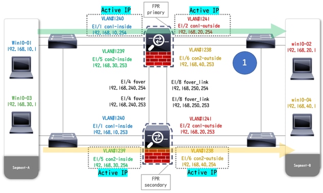 Before Link Down
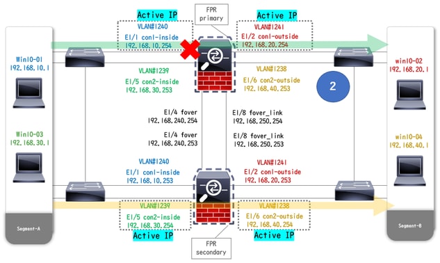 During Link Down
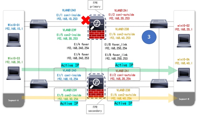 Failover Triggered
Step 1. Initiate FTP Connection From Win10-01 to Win10-02
Step 2. Confirm FTP Connection Before Failover
Run changeto context con1 to connect con1 context from system context. Confirm that an FTP connection is established in both ASA units.
asa/act/pri/con1# show conn
5 in use, 11 most used

! --- Confirm the connection in Primary Unit
TCP con1-outside 192.168.20.1:21 con1-inside 192.168.10.1:49703, idle 0:00:11, bytes 528, flags UIO

asa/stby/sec/con1# show conn
5 in use, 11 most used

! --- Confirm the connection in Secondary Unit
TCP con1-outside 192.168.20.1:21 con1-inside 192.168.10.1:49703, idle 0:00:14, bytes 528, flags UIO
Step 3. LinkDOWN E1/1 of Primary Unit
Step 4. Confirm Failover Status
In system context, confirm that failover occurs in group 1.

Note: The status of failover match traffic flow condition 4.
asa/act/sec# show failover
Failover On
Failover unit Secondary
Failover LAN Interface: fover Ethernet1/4 (up)
......
Group 1 last failover at: 20:00:16 JST Jan 11 2024
Group 2 last failover at: 17:02:33 JST Jan 11 2024

This host: Secondary
Group 1 State: Active  <--- group 1 of Secondary Unit is Switching to Active
Active time: 5 (sec)
Group 2 State: Active
Active time: 10663 (sec)

con1 Interface con1-inside (192.168.10.254): Normal (Waiting)
con1 Interface con1-outside (192.168.20.254): Normal (Waiting)
con2 Interface con2-inside (192.168.30.254): Normal (Monitored)
con2 Interface con2-outside (192.168.40.254): Normal (Monitored)

Other host: Primary
Group 1 State: Failed  <--- group 1 of Primary Unit is Switching to Failed status
Active time: 434 (sec)
Group 2 State: Standby Ready
Active time: 117 (sec)

con1 Interface con1-inside (192.168.10.253): Failed (Waiting)
con1 Interface con1-outside (192.168.20.253): Normal (Waiting)
con2 Interface con2-inside (192.168.30.253): Normal (Monitored)
con2 Interface con2-outside (192.168.40.253): Normal (Monitored)
Step 5. Confirm FTP Connection After Failover
Run changeto context con1 to connect con1 context from system context, confirm that the FTP connection is not interrupted.
asa/act/sec# changeto context con1
asa/act/sec/con1# show conn
11 in use, 11 most used

! --- Confirm the target FTP connection exists in group 1 of the Secondary Unit
TCP con1-outside 192.168.20.1:21 con1-inside 192.168.10.1:49703, idle 0:00:09, bytes 529, flags UIO
Step 6. Confirm Behavior of Preempt Time
LinkUP E1/1 of the Primary Unit and wait for 30s (preempt time), the failover state returns to the original state (match traffic flow in pattern 1).
asa/stby/pri#
Group 1 preempt mate    <--- Failover is triggered automatically, after the preempt time has passed

asa/act/pri# show failover
Failover On
Failover unit Primary
Failover LAN Interface: fover Ethernet1/4 (up)
......
Group 1 last failover at: 11:02:33 UTC Jan 11 2024
Group 2 last failover at: 08:02:45 UTC Jan 11 2024

This host: Primary
Group 1 State: Active  <--- group 1 of Primary Unit is switching to Active status
Active time: 34 (sec)
Group 2 State: Standby Ready
Active time: 117 (sec)

con1 Interface con1-inside (192.168.10.254): Normal (Monitored)
con1 Interface con1-outside (192.168.20.254): Normal (Monitored)
con2 Interface con2-inside (192.168.30.253): Normal (Monitored)
con2 Interface con2-outside (192.168.40.253): Normal (Monitored)

Other host: Secondary
Group 1 State: Standby Ready  <---- group 1 of Secondary Unit is switching to Standby status
Active time: 125 (sec)
Group 2 State: Active
Active time: 10816 (sec)

con1 Interface con1-inside (192.168.10.253): Normal (Monitored)
con1 Interface con1-outside (192.168.20.253): Normal (Monitored)
con2 Interface con2-inside (192.168.30.254): Normal (Monitored)
con2 Interface con2-outside (192.168.40.254): Normal (Monitored)
Virtual MAC Address
In Active/Active failover, virtual MAC address (manually set value, or automatically generated value, or default value) is always used. The active virtual MAC address is associated with the Active Interface.
Manually Setting of Virtual MAC Address
In order to set the virtual MAC address for physical interfaces manually, the mac address command or the mac-address command (within I/F setting mode) can be used. This is an example of manually setting a virtual MAC address for the physical Interface E1/1.

Caution: Please avoid using these two types of commands within same device.
asa/act/pri(config)# failover group 1
asa/act/pri(config-fover-group)# mac address E1/1 1234.1234.0001 1234.1234.0002

asa/act/pri(config-fover-group)# changeto context con1
asa/act/pri/con1(config)# show interface E1/1 | in MAC
MAC address 1234.1234.0001, MTU 1500 <--- Checking virtual MAC on the Primary Unit(con1) side

asa/stby/sec# changeto context con1
asa/stby/sec/con1# show interface E1/1 | in MAC
MAC address 1234.1234.0002, MTU 1500 <--- Checking virtual MAC on the Secondary Unit(con1) side
OR
asa/act/pri(config)# changeto context con1
asa/act/pri/con1(config)# int E1/1
asa/act/pri/con1(config-if)# mac-addr 1234.1234.0001 standby 1234.1234.0002

asa/act/pri/con1(config)# show interface E1/1 | in MAC
MAC address 1234.1234.0001, MTU 1500 <--- Checking virtual MAC on the Primary Unit(con1) side

asa/stby/sec# changeto context con1
asa/stby/sec/con1# show interface E1/1 | in MAC
MAC address 1234.1234.0002, MTU 1500<--- Checking virtual MAC on the Secondary Unit(con1) side
Automatically Setting of Virtual MAC Address
Automatically generating of virtual MAC address is also supported. It can be achieved by using the mac-address auto <prefix prefix> command. The format of virtual MAC address is A2 xx.yyzz.zzzz which is being generated automatically.
A2 : fixed value
xx.yy : generated by the <prefix prefix> specified in the command option (The prefix is converted to hexadecimal and then inserted by reverse order).
zz.zzzz : generated by an internal counter
This is an example about generating virtual MAC address by mac-address auto command for interface.
asa/act/pri(config)# mac-address auto
INFO: Converted to mac-address auto prefix 31

asa/act/pri(config)# show run all context con1 <--- Checking the virtual MAC addresses generated on con1 context
allocate-interface Ethernet1/1
mac-address auto Ethernet1/1 a21f.0000.0008 a21f.0000.0009
allocate-interface Ethernet1/2
mac-address auto Ethernet1/2 a21f.0000.000a a21f.0000.000b
config-url disk0:/con1.cfg
join-failover-group 1

asa/act/pri(config)# show run all context con2 <--- Checking the virtual MAC addresses generated on con2 context
context con2
allocate-interface Ethernet1/5
mac-address auto Ethernet1/5 a21f.0000.000c a21f.0000.000d
allocate-interface Ethernet1/6
mac-address auto Ethernet1/6 a21f.0000.000e a21f.0000.000f
config-url disk0:/con2.cfg
join-failover-group 2
Default Setting of Virtual MAC Address
In case neither automatic nor manual generation of a virtual MAC address is set, the default virtual MAC address is used.
For more information about default virtual MAC address, please refer to the Command Default of mac address in Cisco Secure Firewall ASA Series Command Reference Guide.
Upgrade
You can achieve zero downtime upgrade of an Active/Active failover pair using CLI or ASDM. For more information, please refer to Upgrade an Active/Active Failover Pair.
Revision History
| Revision | Publish Date | Comments |
|---|---|---|
1.0 |
07-Feb-2024
|
Initial Release |
Contributed by Cisco Engineers
- Jian ZhangCisco Technical Consulting Engineer
Contact Cisco
- Open a Support Case

- (Requires a Cisco Service Contract)
 Feedback