Perform Diagnostic Tests from the LCD Panel of a FirePOWER Appliance
Available Languages
Contents
Introduction
This document describes how to run diagnostic tests on the Cisco FirePOWER 7000 and 8000 Series appliances from the LCD panel.
Background Information
This section describes the LCD panel components and some important considerations before you begin the diagnostic tests.
LCD Panel Components
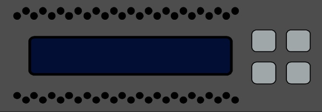
The LCD panel has these components:
- Display – The display contains two lines of text and a multi-function key map. The key map indicates the actions that you can perform with each multi-function key.
- Multi-function keys – There are four multi-function keys (buttons) on the LCD panel that allow you to view system information and complete basic configuration tasks, which vary dependent upon the LCD panel mode:
- The left two buttons are used in order to navigate up and down in a list.
- The right two buttons are used in order to select one of the two items that are displayed on the panel.
- The left two buttons are used in order to navigate up and down in a list.
This image illustrates the LCD panel display and buttons:

Important Considerations
Before you run the diagnostic tests, ensure that you consider this important information:
- The device must be taken out of the production network before you run the diagnostic tests.
- When you run the diagnostic tests, traffic will be interrupted. Cisco recommends that you perform the diagnostic tests during a maintenance window.
- In order for the loopback test to run as a part of the diagnostic tests, you must ensure that the cable connections are configured properly between the various ports, as described in the next section.
Loopback Test Preparation
If you plan to include the loopback test as a part of the diagnostic tests, you must use one short Ethernet cable for every two ports on the device.
For example, on a 3D7120 Series device with eight ports, connect the cables like this:
- Port 1 to Port 3
- Port 2 to Port 4
- Port 5 to Port 7
- Port 6 to Port 8
On 8000 Series devices, the cable connections depend upon the netmods that are installed. For 4-port netmods, both copper and fiber, connect the cables on each netmod like this:
- Port 1 to Port 3
- Port 2 to Port 4
Stacked netmods must have Port 1 and Port 2 connected to each other. If a system uses 2-port netmods of the same type (Long Reach (LR) or Short Reach (SR)), the netmods must be daisy-chained to each other. For example, Port 2 of one netmod must be connected to Port 1 of the next netmod, and must loop back to the first netmod.
Run Diagnostic Tests from the LCD Panel
Complete these steps in order to run the diagnostic tests:
- Connect the Ethernet cables as described in the previous section.
- Press any LCD panel button in order to begin.
- Select System Status.
- Navigate to and select Diagnostics.
- Select Enter Combination.
- Complete the actions that are indicated on the LCD panel, and then press and hold the button that corresponds to the flashing symbol for five seconds.
- A warning message appears. After the warning message disappears, use the top-left button in order to select Accept: Run diags.
- Select the test that you want to perform (you should perform both tests):
- Media Diags
- NFE0 Diags
- If all of the tests pass, then the LCD display shows Media DIAGS PASSED or NFE DIAGS PASSED. Otherwise, the screen displays a list of tests that failed, with Exit shown at the bottom of the screen. If any of the tests have failed, record them and select Exit.
- Reboot the device.
Contact Cisco
- Open a Support Case

- (Requires a Cisco Service Contract)
 Feedback