Configure Nexus Dashboard Orchestrator to Migrate Endpoint from One DC to another DC
Available Languages
Download Options
Bias-Free Language
The documentation set for this product strives to use bias-free language. For the purposes of this documentation set, bias-free is defined as language that does not imply discrimination based on age, disability, gender, racial identity, ethnic identity, sexual orientation, socioeconomic status, and intersectionality. Exceptions may be present in the documentation due to language that is hardcoded in the user interfaces of the product software, language used based on RFP documentation, or language that is used by a referenced third-party product. Learn more about how Cisco is using Inclusive Language.
Contents
Introduction
This document describes the design and configuration changes required to migrate an Endpoint from one Data Center to another Data Center.
Physical Topology
Figure 1. depicts the interconnectivity of two Data Centers.
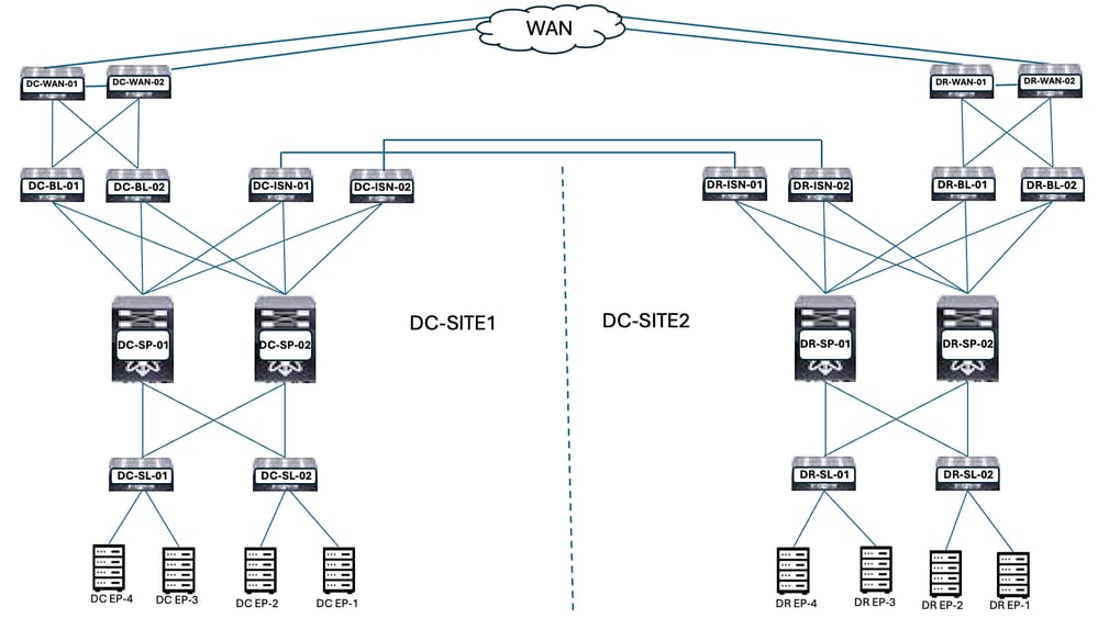
Figure 1: Physical Topology
DC and DR locations have the Application Centric Infrastructure (ACI). DC and DR locations have the WAN Switches, Border Leaf, Spines, Inter-Site Network Devices (ISN), Server Leaf, and connected Endpoints.
Logical Topology
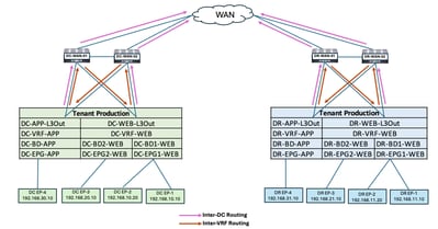
Figure 2: Logical Topology
Logical objects configured in both sites:
- Tenant Production is configured at the DC and DR sites.
- DC-VRF-WEB and DC-VRF-APP are configured in DC-SITE1. DR-VRF-WEB and DR-VRF-APP are configured in DR-SITE2.
- Each VRF is configured with local L3Outs on Border Leaf towards WAN Switches. Default routes are configured on Border Leaf towards WAN Switches.
- WAN Switches are configured with Static routing for Inter-VRF and Inter-DC communication.
- Both Data Centers are configured with Local BDs and EPGs. DC has DC-BD1-WEB/DC-EPG1-WEB, DC-BD2-WEB/DC-EPG2-WEB and DC-BD-APP/DC-EPG-APP. DR has DR-BD1-WEB/DR-EPG1-WEB, DR-BD2-WEB/DR-EPG2-WEB and and DR-BD-APP/DR-EPG-APP.
- There are endpoints connected in WEB and APP EPG.
- DC-SITE1 and DR-SITE2 are added to the Nexus Dashboard Orchestrator.
Traffic Flow Before Endpoint Migration
There are multiple types of Traffic Flow in Data Centers:
- Intra EPG Traffic flow
- Inter EPG Traffic flow
- Inter VRF Traffic flow
- Inter DC Traffic flow
Intra EPG Traffic Flow
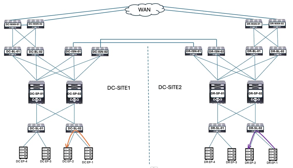
Figure 3: Intra EPG Traffic Flow
Communication between DC-EP-1 and DC-EP-2 is Intra EPG communication, as both Endpoints belong to DC-EPG1-WEB. Communication between DR-EP-1 and DR-EP-2 is Intra EPG communication, as both Endpoints belong to DR-EPG1-WEB.
Inter EPG Traffic Flow
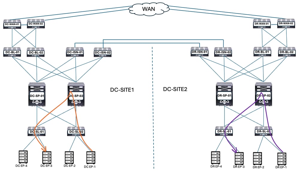
Figure 4: Inter EPG Traffic Flow
DC-EP-1 and DC-EP-3 are part of DC-EPG1-WEB and DC-EPG2-WEB respectively, communication between these two Endpoints is Inter EPG Traffic Flow. DR-EP-1 and DR-EP-3 are part of DR-EPG1-WEB and DR-EPG2-WEB respectively, communication between these two Endpoints is Inter EPG Traffic Flow.
Inter VRF Traffic Flow
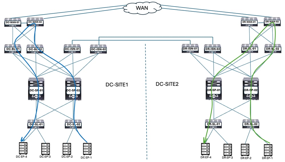
Figure 5: Inter VRF Traffic Flow
DC Border Leaf forwards the traffic to DC WAN Switches for any Inter-VRF communication. DC WAN Switches are used for Inter-VRF communication. DC-EP-1/EP-2 (VRF WEB) communicates to DC-EP-4 (VRF APP) through WAN Switches. DR Border Leaf forwards the traffic to DR WAN Switches for any Inter-VRF communication. DR WAN Switches are used for Inter-VRF communication. DR-EP-1/EP-2 (VRF WEB) communicates to DR-P-4 (VRF APP) through WAN Switches.
Inter DC Traffic Flow
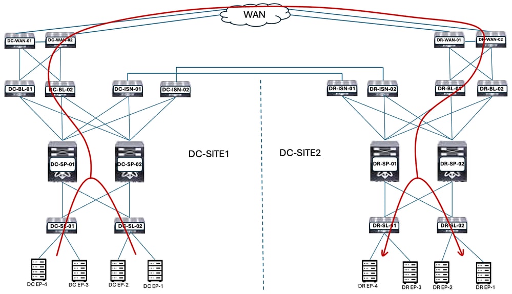
Figure 6: Inter DC Traffic Flow
Communication between DC-Endpoints and DR-Endpoints forwarded to Border Leaf. Border Leaf forwards the traffic to WAN Switches. WAN Switches are used for Inter DC communication.
Migration Plan
Nexus Dashboard Orchestrator is used to create the Multisite between both the sites, EPGs/BDs stretched across sites and endpoints must be migrated from DC-SITE1 to DR-SITE2.
Schema-1 Creation
Schema-1 was created through Nexus Dashboard Orchestrator.
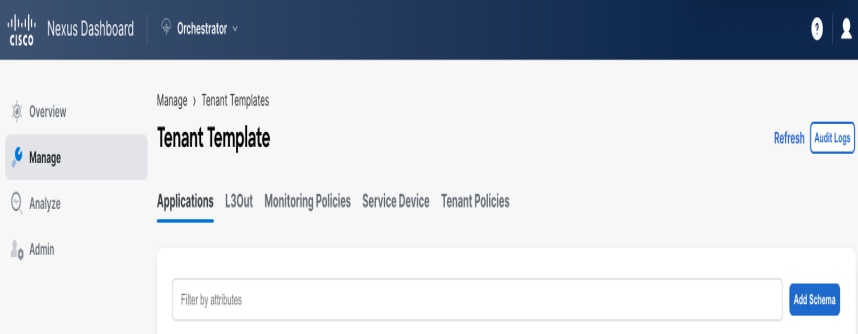
Figure 7: Tenant Template - Add Schema
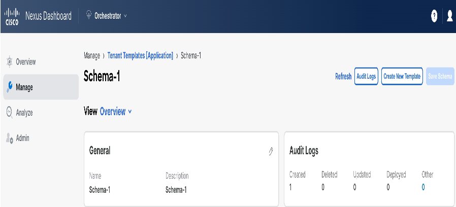
Figure 8: Add Schema Name
Template-VRF-Contract-Stretched Creation
Template-VRF-Contract-Stretched created inside Schema-1. DC-SITE1 and DR-SITE2 must be part of this Template and Tenant-Production in order to be associated with the same Template. This is a stretched template. VRF and Contracts must be part of a separate Template, as these objects are shared across other BD/EPGs. This template must be used in order to stretch the DC-SITE1 VRF and Contract to DR-SITE2.
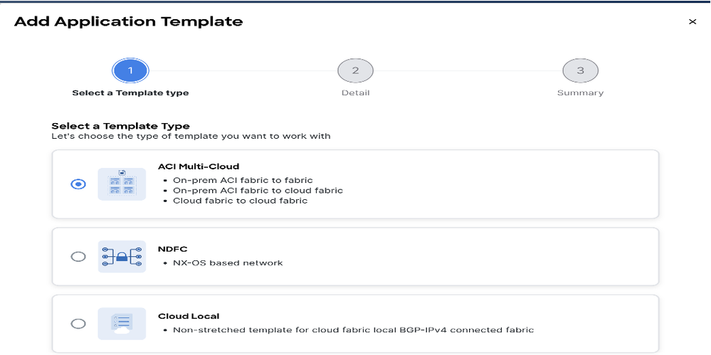
Figure 9: Add Application Template - Choose ACI Multi-Cloud
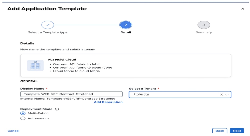
Figure 10: Add Template Name Template-WEB-VRF-Contract-Stretched, Choose Tenant Production
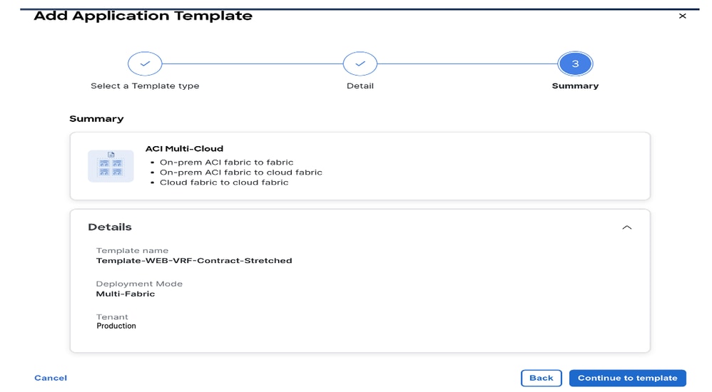
Figure 11: Template-WEB-VRF-Contract-Stretched Details
Import VRF-Contract in Template-VRF-Contract-Stretched
Import DC-VRF-WEB and DC-VRF-WEB-Contract from DC-SITE1. Contracts are created for Inter-EPG communication and EPG-to-L3Out communication.
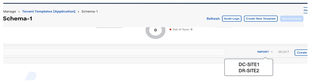
Figure 12: Click Import and Choose DC-SITE1
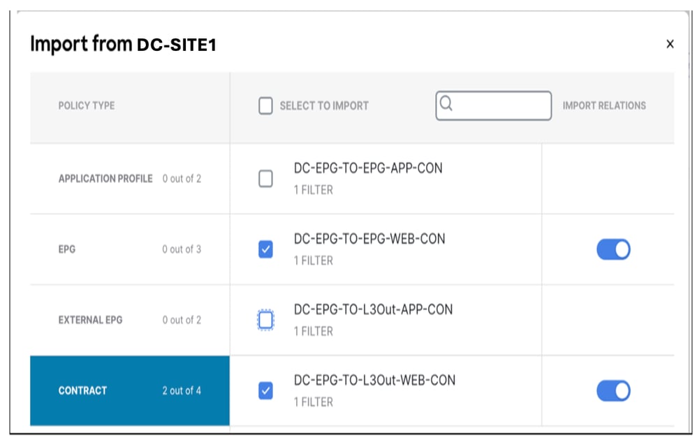
Figure 13: Choose Contract from DC-SITE1
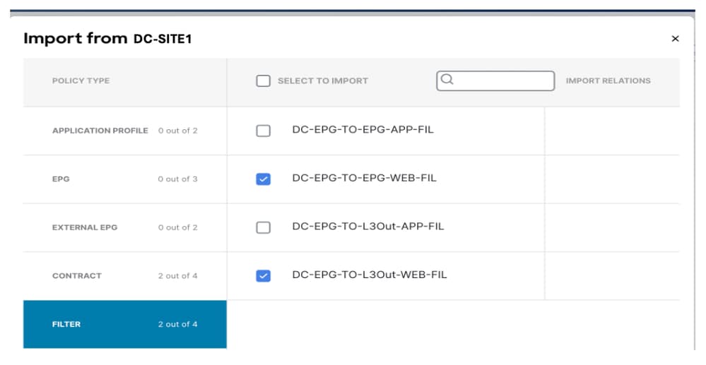
Figure 14: Choose Filter from DC-SITE1
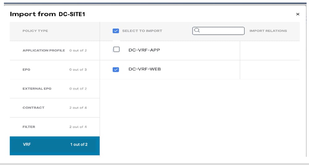
Figure 15: Choose VRF from DC-SITE1
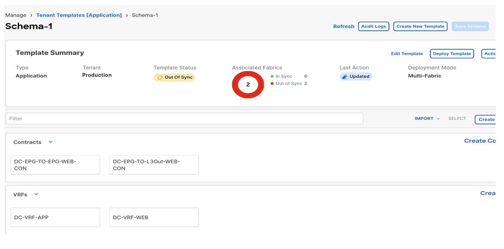
Figure 16: Template-WEB-VRF-Contract-Stretched with VRF and Contract Information
Deploy Template-VRF-Contract-Stretched
Click Deploy Template-VRF-Contract-Stretched and choose DC-SITE1 and DR-SITE2.
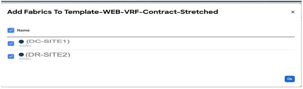
Figure 17:Add Fabrics to Template-VRF-Contract-Stretched
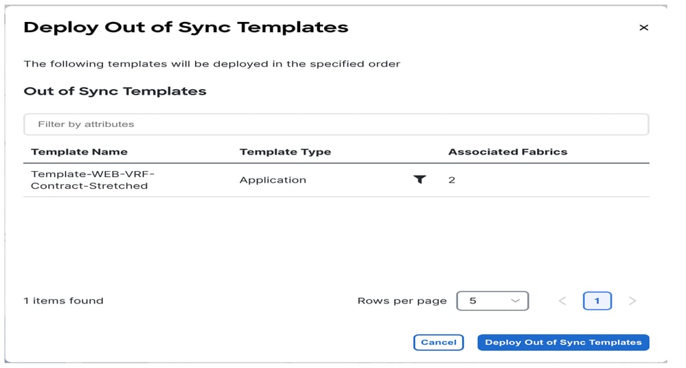
Figure 18: Deploy Out-of-Sync Templates
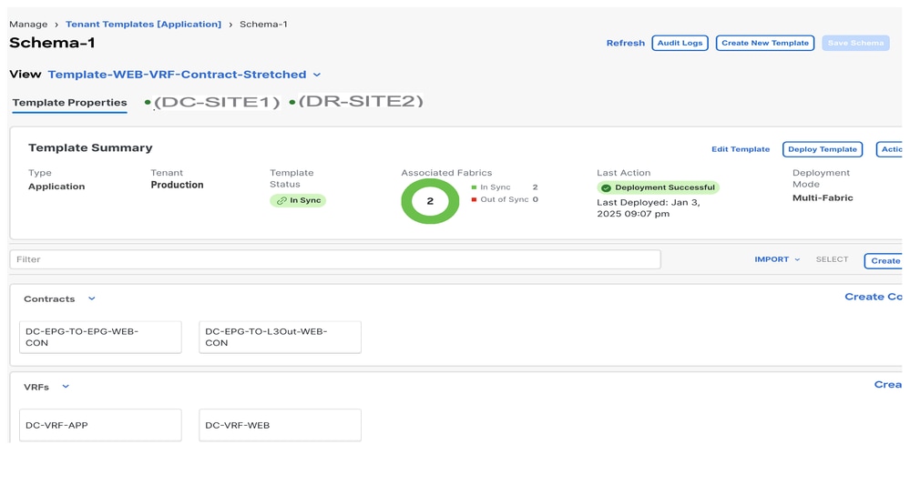
Figure 19: Deployment Completed
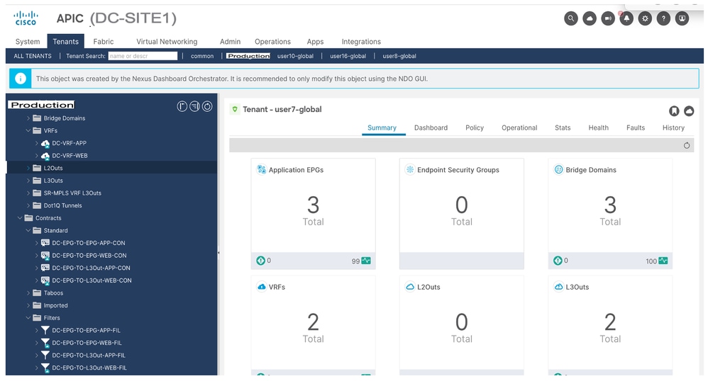
Figure 20: Verify VRF and Contracts Deployed on Both Sites

Template-EPG1-BD1-Stretched Creation
Template-EPG1-BD1-Stretched created inside Schema-1. DC-SITE1 and DR-SITE2 were added to Template and Tenant-Production associated with the same Template. This is a stretched template. This template is used in order to stretch DC-EPG1-WEB and DC-BD1-WEB to DR-SITE2.

Figure 21: Add Application Template - Choose ACI Multi-Cloud
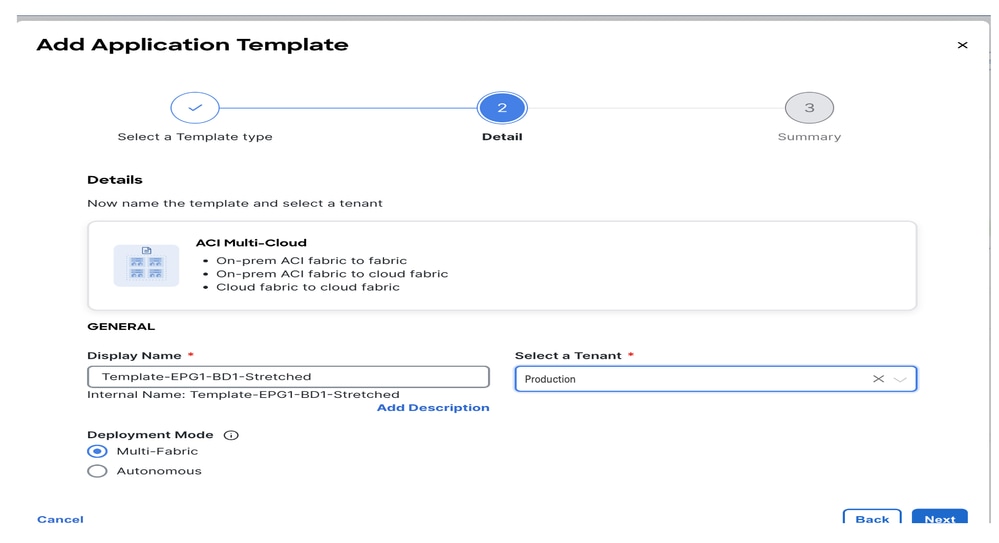
Figure 22: Add Template name Template-EPG1-BD1-Stretched, Choose Tenant Production
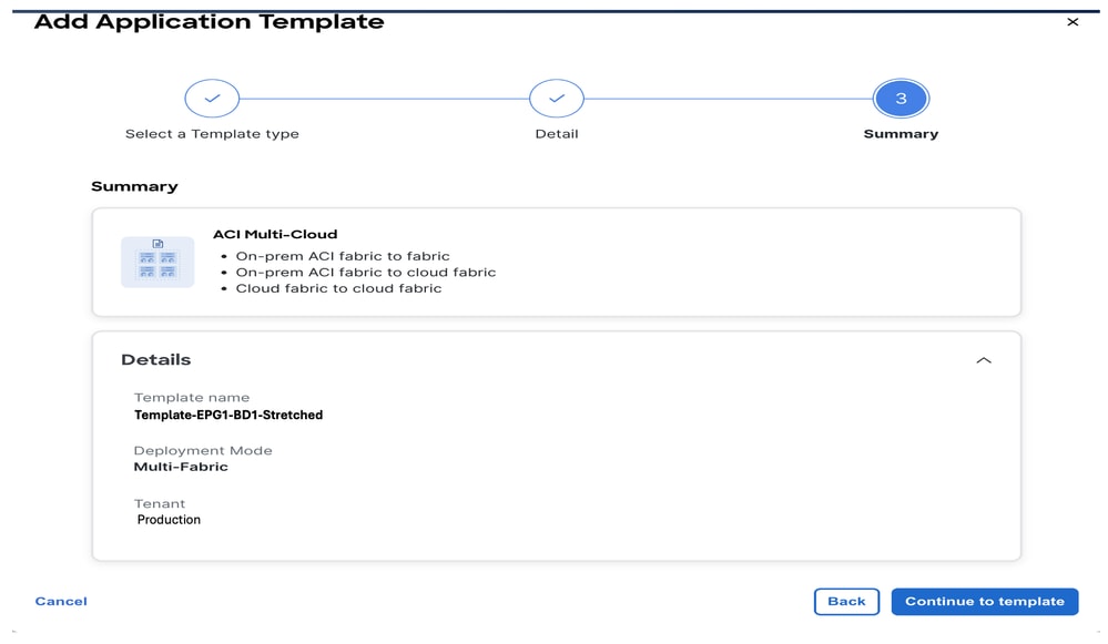
Figure 23: Template-EPG1-BD1-Stretched Details
Import EPG1-BD1 in Template-EPG1-BD1-Stretched
Import DC-EPG1-WEB and DC-BD1-WEB from DC-SITE1.
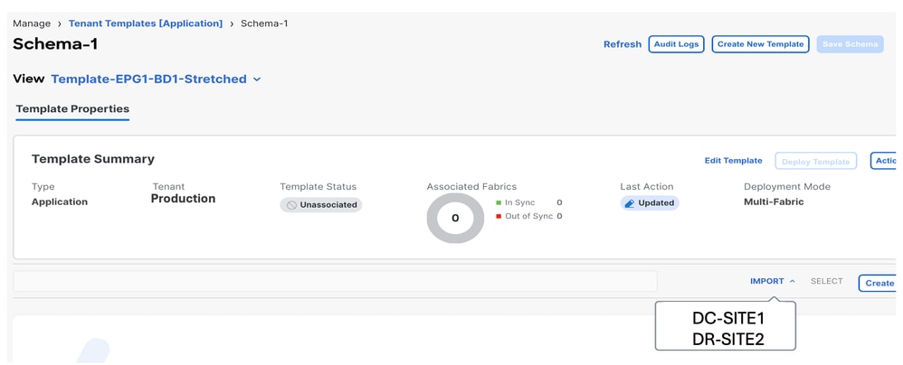
Figure 24: Click Import and Choose DC-SITE1
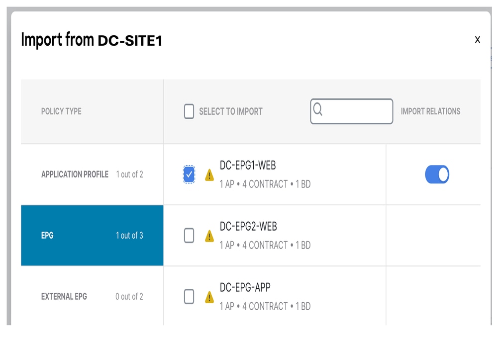
Figure 25: Choose DC-EPG1-WEB from DC-SITE1
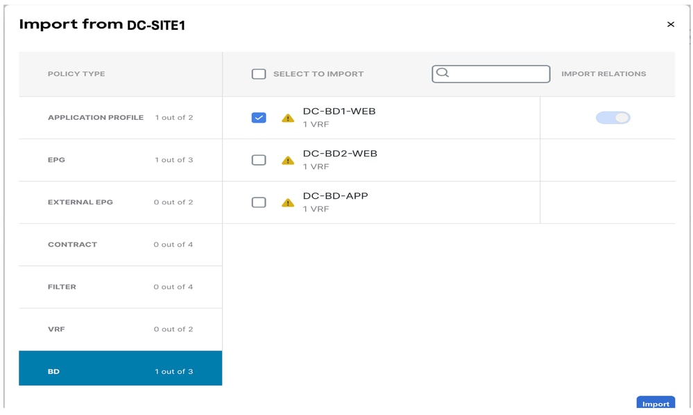
Figure 26: Choose DC-BD1-WEB from DC-SITE1
Change BD Setting in Template-EPG1-BD1-Stretched
Enable L2 Stretch in DC-BD1-WEB settings and add the Gateway IP Address. This template stretches BD across the site and the anycast Gateway configured in DC-SITE1 and DR-SITE2.
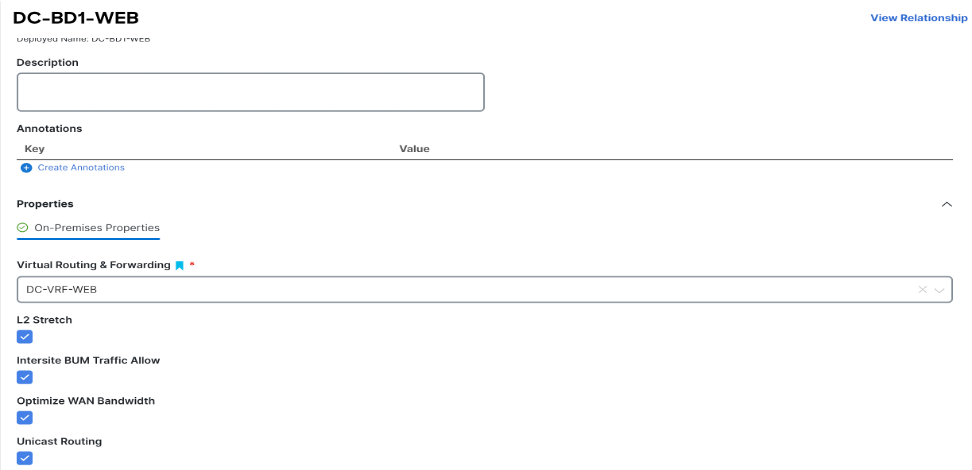
Figure 27: Choose L2 Stretch in DC-BD1-WEB
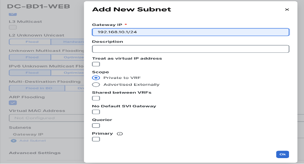
Figure 28: Add Gateway IP/Subnet
Deploy Template-EPG1-BD1-Stretched
Click Deploy Template-EPG1-BD1-Stretched and choose DC-SITE1 and DR-SITE2.
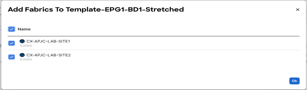
Figure 29: Add Fabrics to Template-EPG1-BD1-Stretched
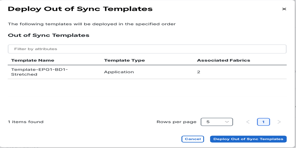
Figure 30: Deploy Out-of-Sync Templates
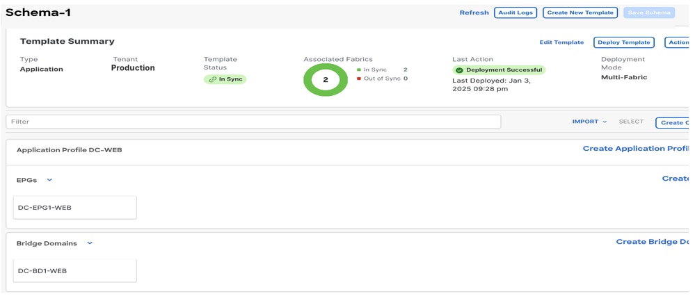
Figure 31: Deployment Completed
Migrate DC-EP-1 from DC-SITE1 to DR-SITE2
Configure static binding in DR-SITE2 in DC-EPG1-WEB and associate DR-SITE2 Physical Domain. Migrate the DC-EP-1 from DC-SITE1 to DR-SITE2.
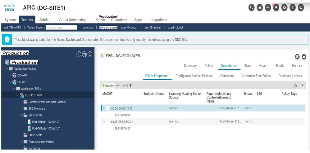
Figure 32: DC-EP-1 Currently Learned in DC-SITE1
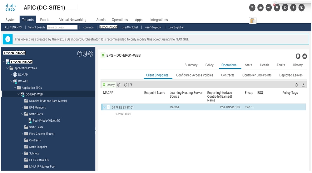
Figure 33: DC-EP-1 removed from DC-SITE1
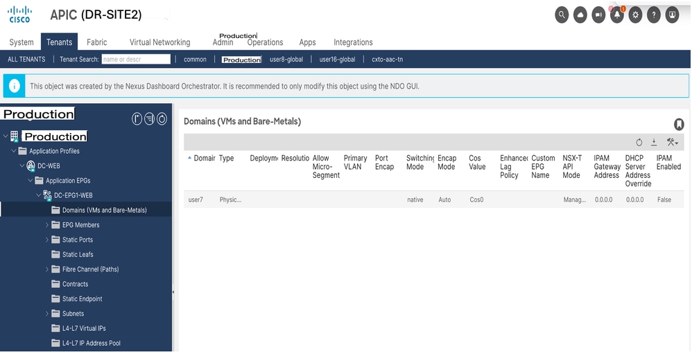
Figure 34: Adding Physical Domain in DR-SITE2
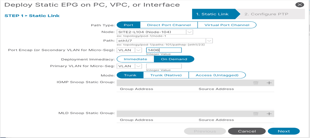
Figure 35: Adding Static Binding in DR-SITE2
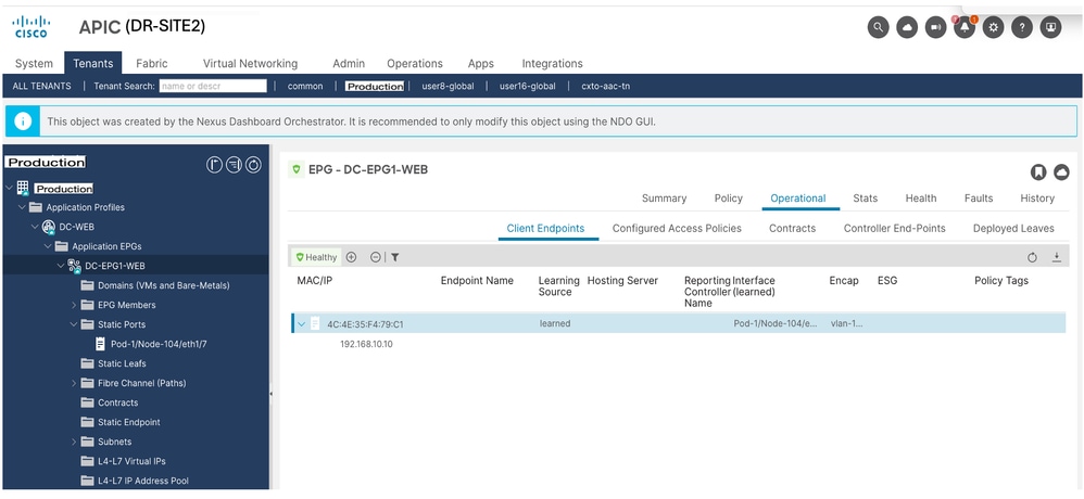
Figure 36: DC-EP-1 Learned in DR-SITE2
Physical Design after DC-EP-1 Migration
DC-EP-1 is connected to DR-SITE2 Server Leaf.
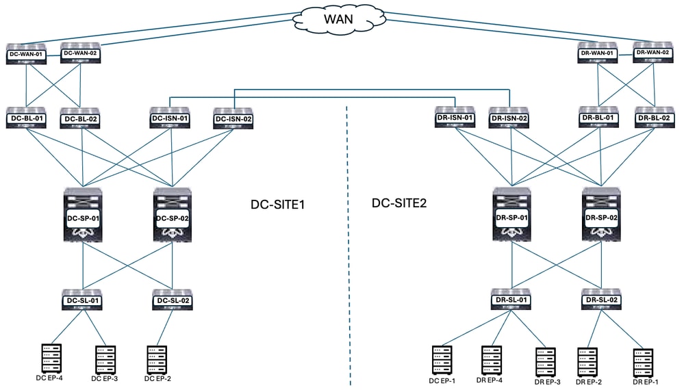
Figure 37: Physical Design after DC-EP-1 Migration
Logical Design after DC-EP-1 Migration
DC-EP-1 is connected to DR-SITE2 Server Leaf. DC-EPG1-WEB, DC-BD1-WEB and DC-VRF-WEB are stretched between DC-SITE1 and DR-SITE2.
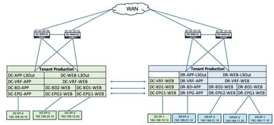
Figure 38: Logical Design after DC-EP-1 Migration
Intra EPG Traffic Flow after DC-EP-1 Migration
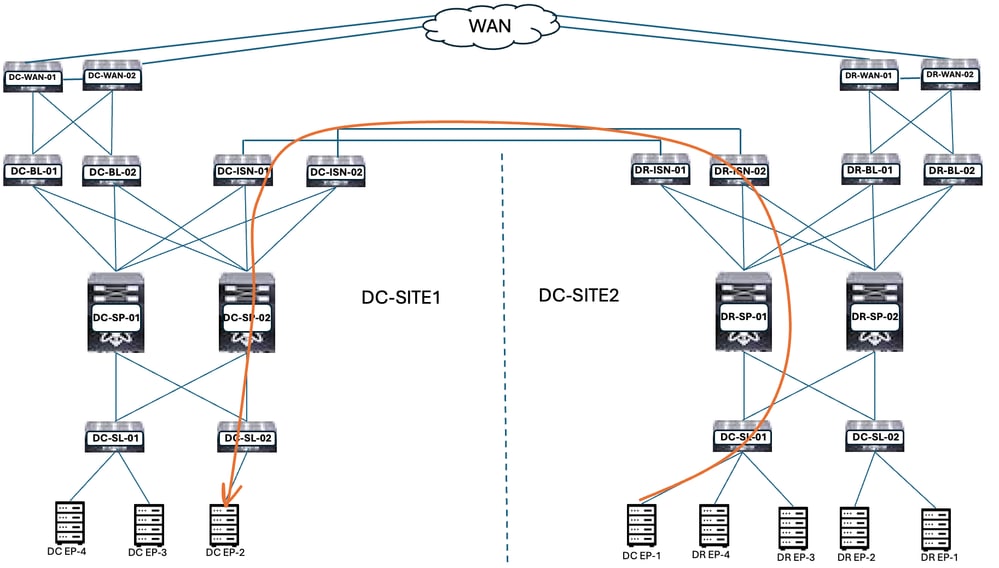
Figure 39: Intra EPG Traffic Flow after DC-EP-1 Migration
Communication between DC-EP-1 and DC-EP-2 is Intra EPG communication, as both Endpoints belong to DC-EPG1-WEB. This communication happens through DC ISN to DR ISN Multisite/Overlay Links.
Ping Response between DC-EP-1 and DC-EP-2
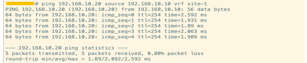
Figure 40: Ping Response Between DC-EP-1 and DC-EP-2
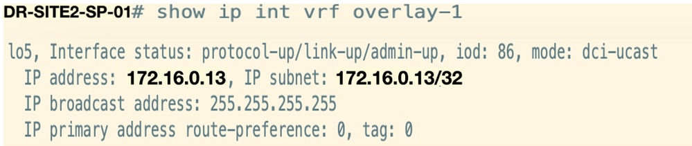
Routing Table from Spines
DC-EP-1 learned in DC-SP-01/DC-SP-02 from DR-SP-01/DR-SP-02.
DC-EP-1 is learned in DC-SITE1-SP-01 from DR-SITE2-SP-01.
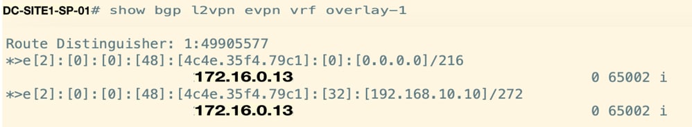
Figure 41: Routing Table from Spines
DR-SITE2-SP-01 Overlay Unicast TEP IP.
Template-EPG2-BD2-Site1 Creation
Inter EPG communication between DC-EP-1 and DC-EP-3 happens, once DC-EPG2-WEB and DC-BD2-WEB are part of the Nexus Dashboard Orchestrator.
Template-EPG2-BD2-Site1 created inside Schema-1. DC-SITE1 added to Template and Tenant-Production associated with the same Template. This is site site-specific template. This template is used to import the Template-EPG2-BD2-Site1 for the communication between DC-EP-1 and DC-EP-3.
DC-EP-1 and DC-EP-3 communication require DC-EPG2-BD2 to be part of Nexus Dashboard Orchestrator.
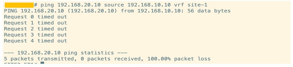
Figure 42: DC-EP-1 and DC-EP-3 Not Able to Communicate

Figure 43: Add Application Template - Choose ACI Multi-Cloud
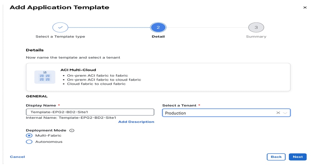
Figure 44: Add Template Name Template-EPG2-BD2-Site1, Choose Tenant Production
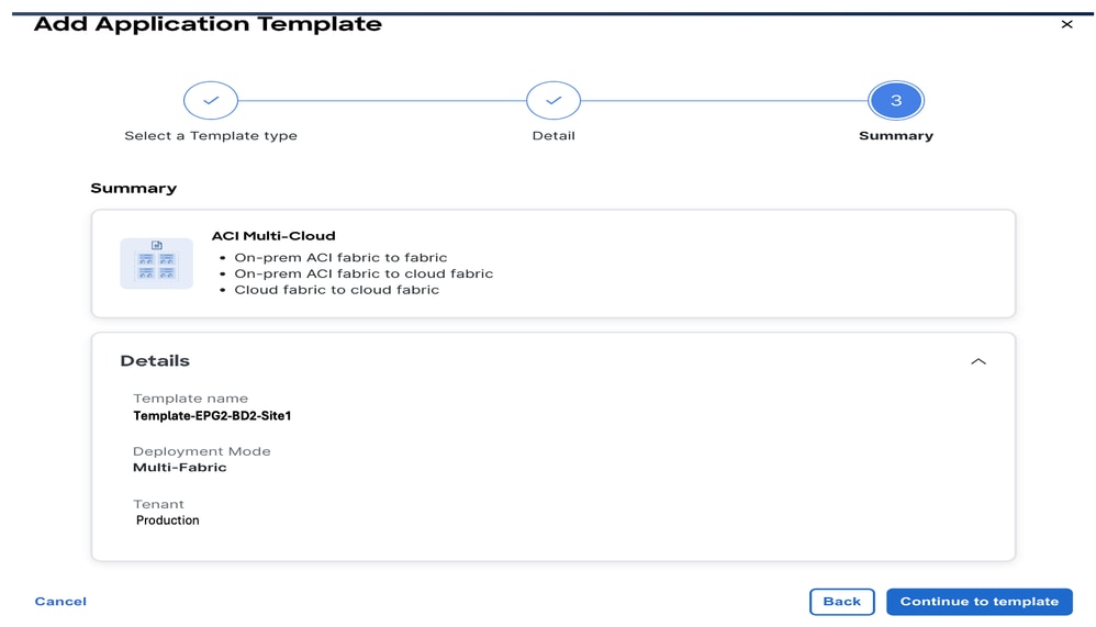
Figure 45: Template-EPG2-BD2-Site1 Details
Import EPG2-BD2 in Template-EPG2-BD2-Site1
Import DC-EPG2-WEB and DC-BD2-WEB from DC-SITE1.
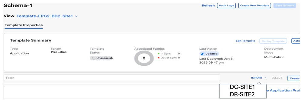
Figure 46: Click Import and Choose DC-SITE1
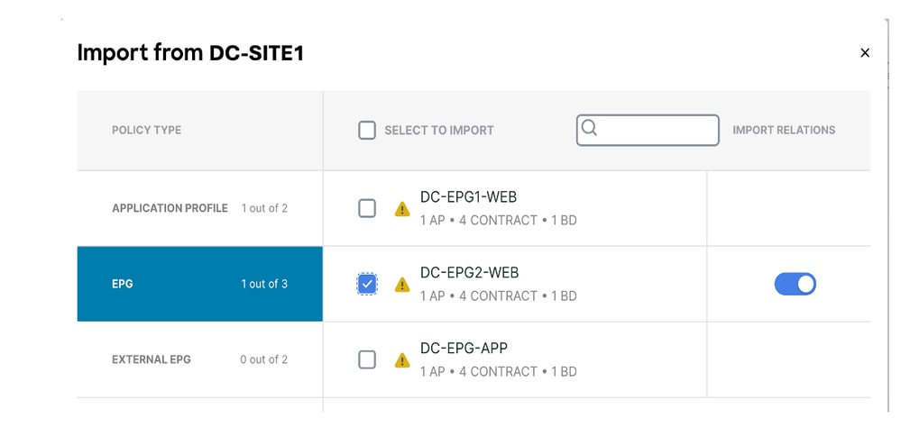
Figure 47: Choose DC-EPG2-WEB from DC-SITE1
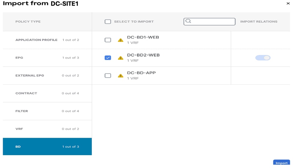
Figure 48: Choose DC-BD2-WEB from DC-SITE1
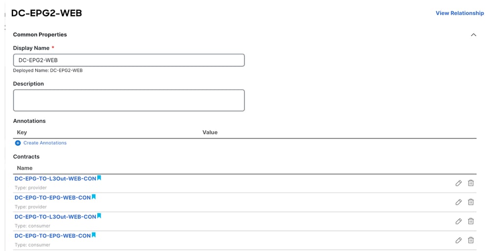
Figure 49: Contracts Associated with DC-EPG2-WEB are Imported
Deploy Template-EPG2-BD2-Site1
Click Deploy Template-EPG2-BD2-Site1 and choose DC-SITE1
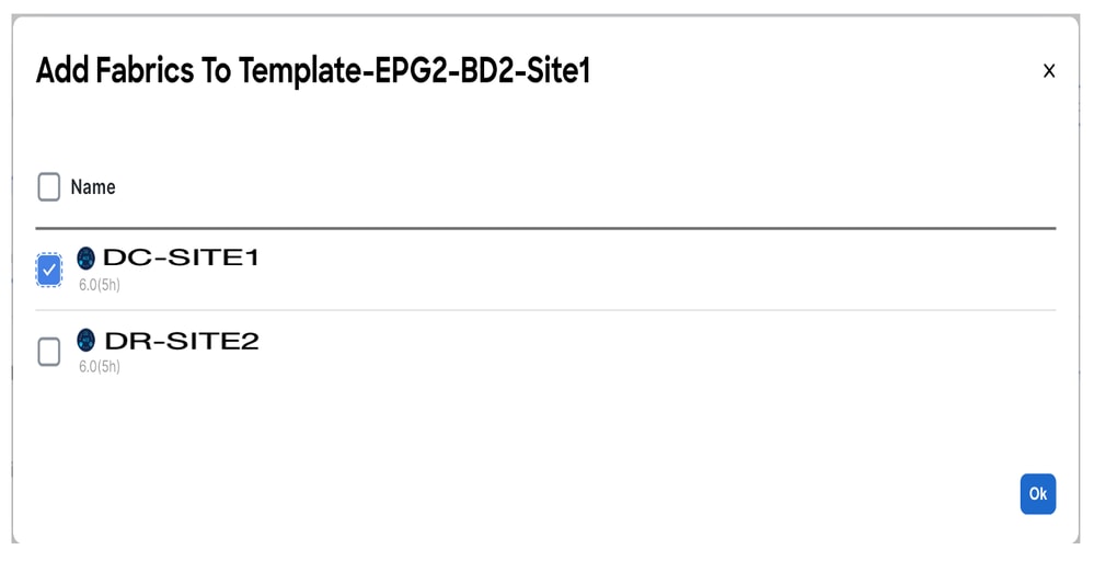
Figure 50: Add Fabrics to Template-EPG2-BD2-Site1
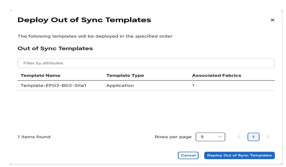
Figure 51: Deploy Out-of- Sync Templates
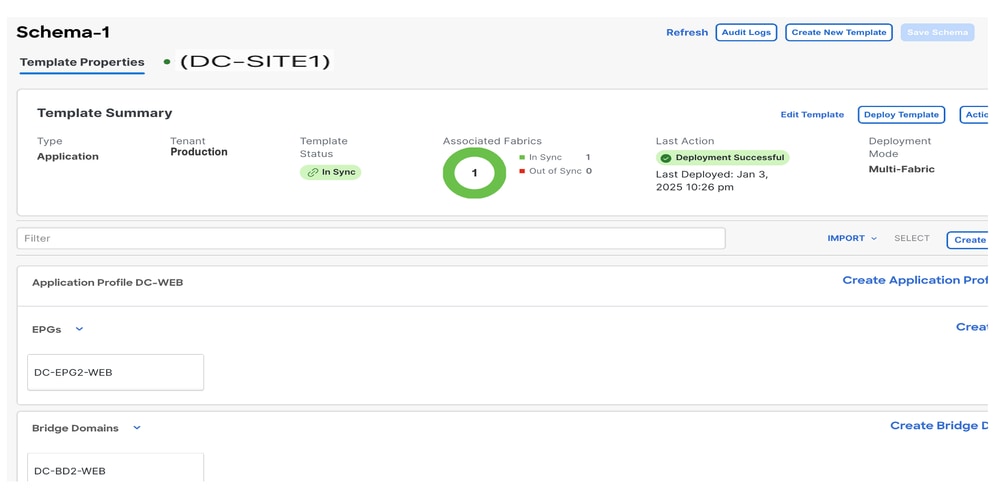
Figure 52: Deployment Completed
Shadow EPG for DC-EPG2-WEB created in DR-SITE2.
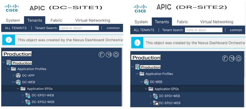
Figure 53: DC-EPG2-WEB is Deployed in Both Sites
Inter EPG Traffic Flow after EP-1 Migration
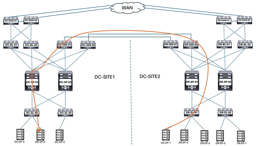
Figure 54: Inter EPG Traffic Flow after EP-1 Migration
Communication between DC-EP-1 and DC-EP-3 is Inter-EPG communication, as both Endpoints belong to DC-EPG1-WEB and DC-EPG2-WEB respectively. This communication happens through DC ISN to DR ISN Multisite/Overlay Links.
Ping Response between DC-EP-1 and DC-EP-3
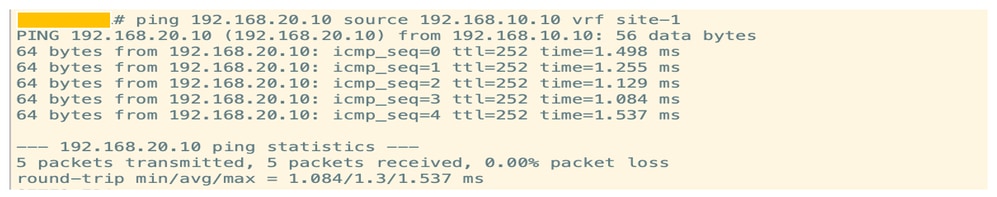
Figure 55: Ping Response between DC-EP-1 and DC-EP-3
Template-WEB-L3Out-Site1 Creation
Template-Web-L3Out-Site1 created inside Schema-1. DC-SITE1 was added to the template and Tenant-Production was associated with the same Template. This is a site-specific template. This template is used for DC-EP-1 Inter-VRF and Inter-DC communication.

Figure 56: Add Application Template - Choose ACI Multi-Cloud
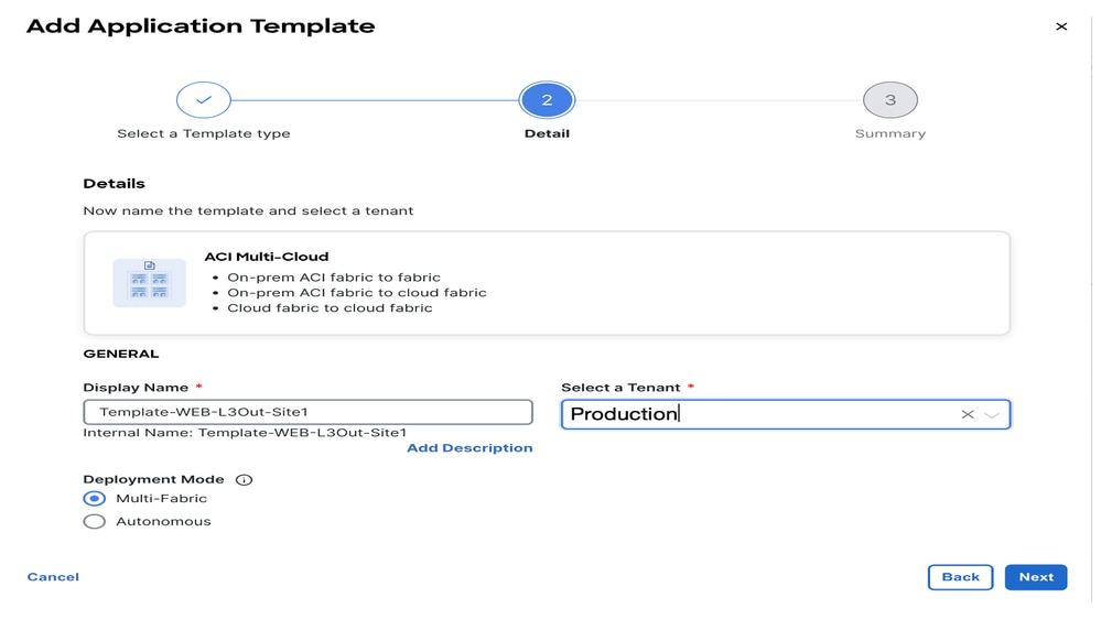
Figure 57: Add Template Name Template-WEB-L3Out-Site1, Choose Tenant Production
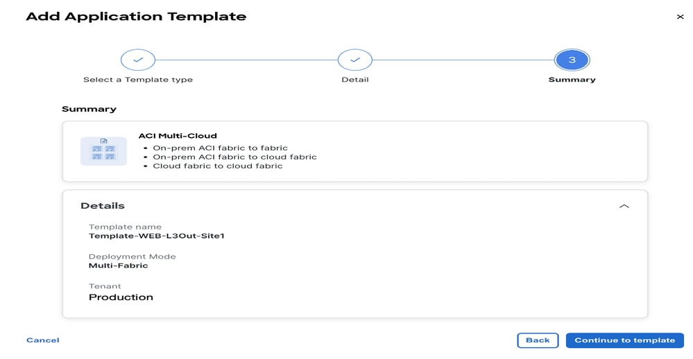
Figure 58: Template-WEB-L3Out-Site1 Details
Import External EPG and L3Out in Template-WEB-L3Out-Site1
Import External EPG and L3Out in Template-WEB-L3Out-Site1
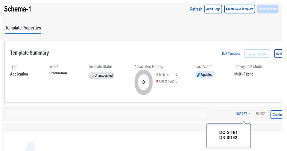
Figure 59: Click Import and Choose DC-SITE1
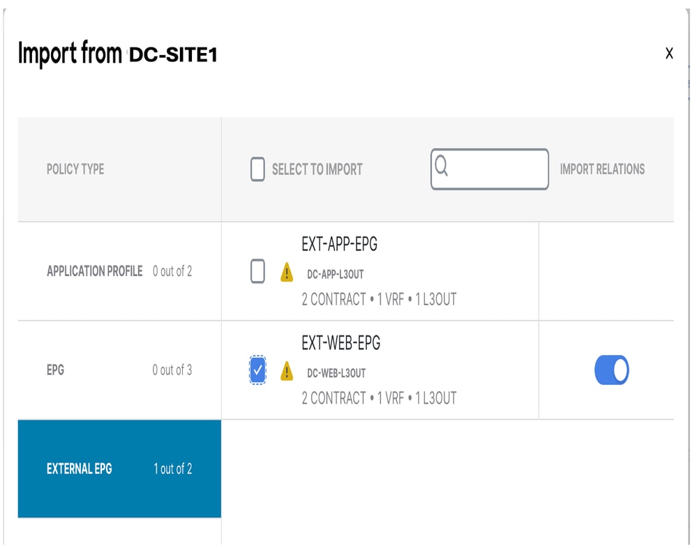
Figure 60: Choose EXT-APP-EPG from DC-SITE1
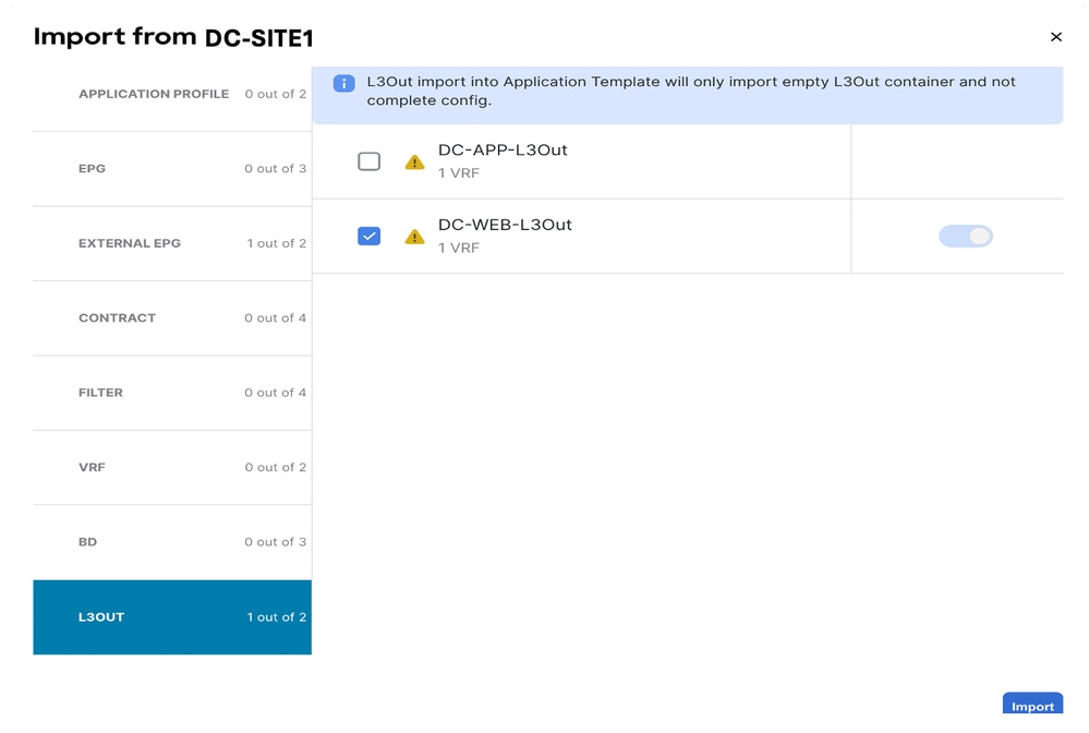
Figure 61: Choose DC-APP-L3Out from DC-SITE1
The shadow of EXT-WEB-EPG was created in DR-SITE2 with applied DC contracts.
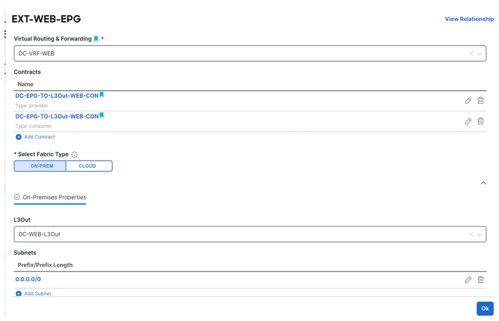
Figure 62: Contracts Associated with EXT-WEB-EPG are Imported
Deploy Template-WEB-L3Out-Site1
Click Deploy Template-WEB-L3Out-Site1 and choose DC-SITE1.
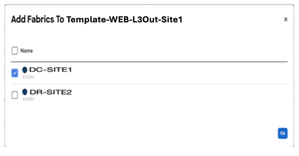
Figure 63: Add Fabrics to Template-WEB-L3Out-Site1
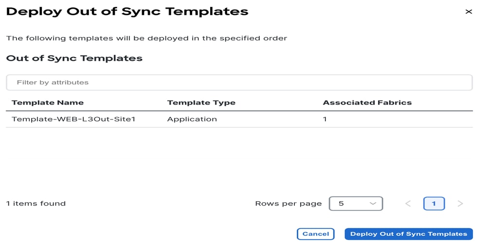
Figure 64:Deploy Out-of-Sync Templates
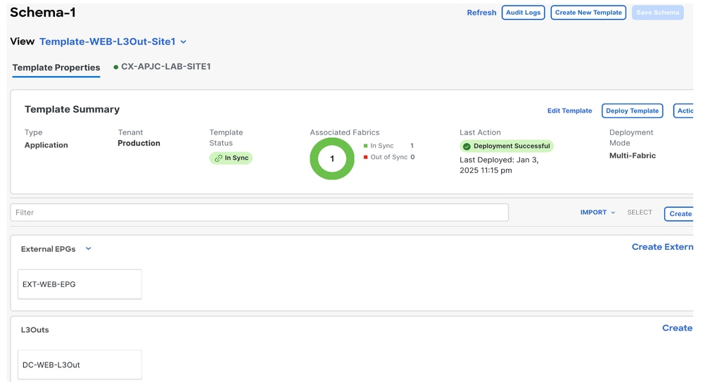
Figure 65: Deployment Completed
Verify the Routes in DR Server Leaf for DC-VRF-WEB
Static routes installed in DR Server Leaf for DC-VRF-WEB.
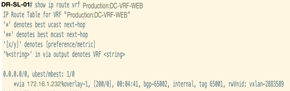
Figure 66: Verify the routes in DR Server Leaf for DC-VRF-WEB
Inter VRF Traffic Flow after DC-EP-1 Migration
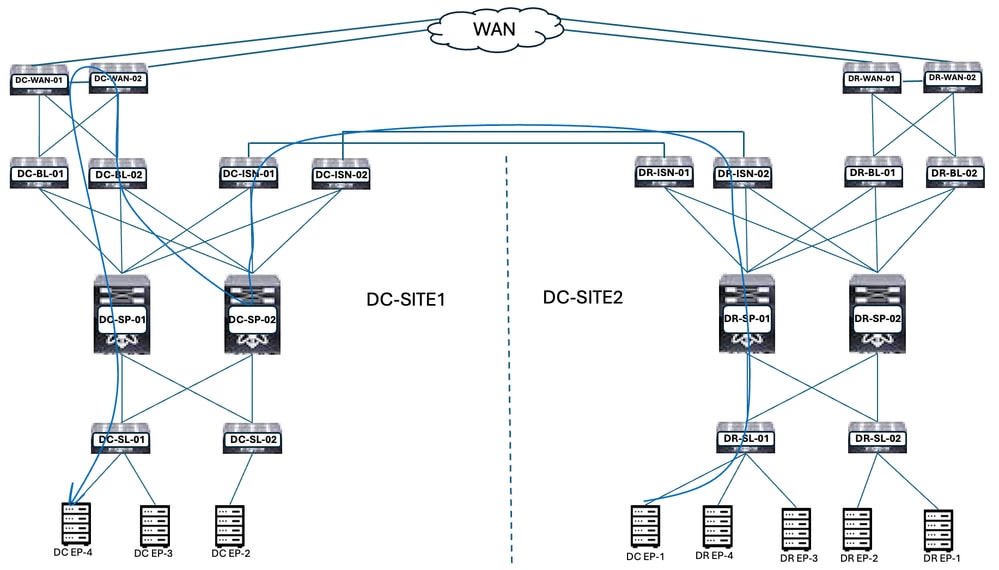
Figure 67: Inter VRF Traffic Flow after DC-EP-1 Migration
DC-EP-1 uses DC-WEB-L3Out in order to communicate with DC-EP-4. The traffic flows from DR-ISN to DC-ISN Multisite Links, DC-ISN to DC-SP-01/DC-SP-02, and from DC-SP to DC-BL. DC-BL-01/DC-BL-02 forward the traffic to DC-WAN Switches for Inter-VRF routing.
Ping Response between DC-EP-1 and DC-EP-4
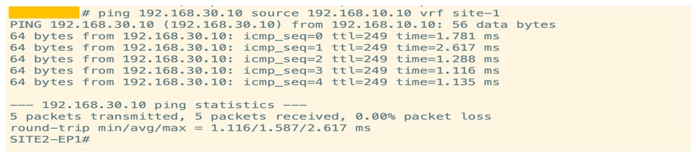
Figure 68: Ping Response Between DC-EP-1 and DC-EP-4
Inter DC Traffic Flow after DC-EP-1 Migration
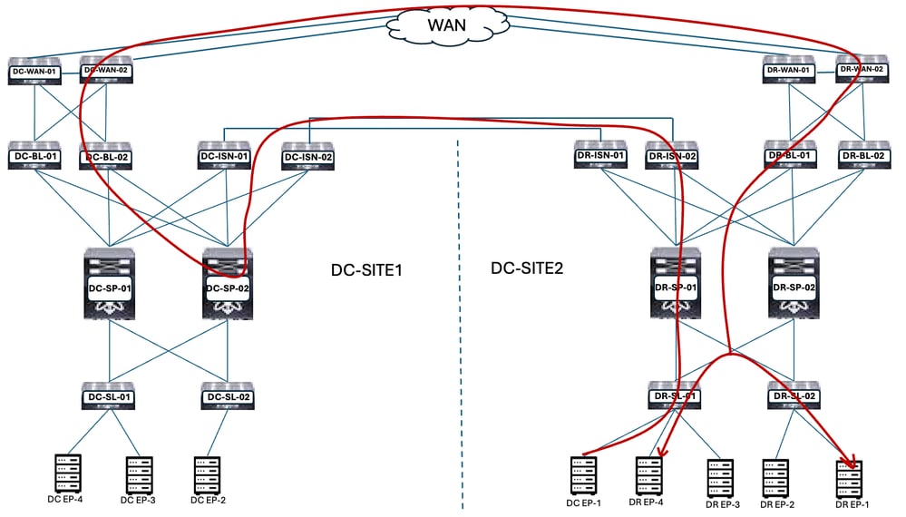
Figure 69: Inter DC Traffic Flow after DC-EP-1 Migration
DC-EP-1 uses DC-WEB-L3Out in order to communicate with DR Endpoints. The traffic flows from DR-ISN to DC-ISN Multisite Links, DC-ISN to DC-SP-01/DC-SP-02, and from DC-SP to DC-BL. DC-BL-01/DC-BL-02 forward the traffic to DC-WAN Switches for DR Endpoints.
Ping Response between DC-EP-1 and DR-EPs
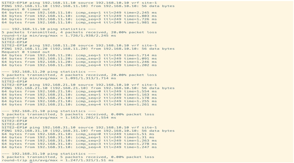
Figure 70: Ping Response Between DC-EP-1 and DR-EPs
Migrate Remaining Endpoints
Physical Design after Remaining Endpoints Migration
After migrating the remaining Endpoints from DC to DR DC-EPG1-WEB, the physical diagram changed accordingly.
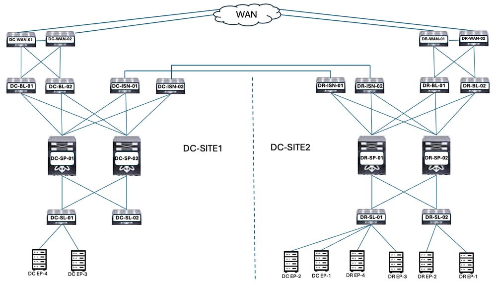
Figure 71: Physical Design after all Endpoints Migration from DC to DR
Logical Design after Remaining Endpoints Migration
DC-EPG1-WEB, DC-BD1-WEB, and DC-VRF-WEB are already stretched between DC and DR Sites. DCs remaining Endpoints migrated from DC to the DR Site.
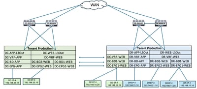
Figure 72: Logical Design after Remaining Endpoint Migration
Intra EPG Traffic Flow after Remaining Endpoint Migration
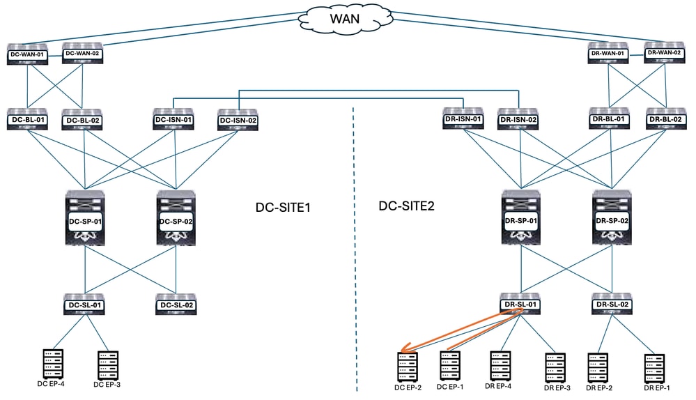
Figure 73: Intra EPG Traffic Flow after Remaining Endpoint Migration
Communication between DC-EP-1 and DC-EP-2 is Intra EPG communication, as both Endpoints belong to DC-EPG1-WEB. This communication happens directly within the DR Site.
Inter EPG, Inter VRF, and Inter DC traffic flows remain similar to DC-EP-1 migration.
Undeploy Template-EPG1-BD1-Stretched from the DC Site
All the Endpoints are migrated from DC to the DR site for DC-EPG1-WEB. DC-EPG1-WEB and DC-BD1-WEB are not required in the DC Site. Undeploy the Template-EPG1-BD1-Stretched from DC Site, this deletes the EPG and BD from Site-1.
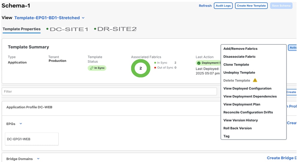
Figure 74: Click Undeploy Template
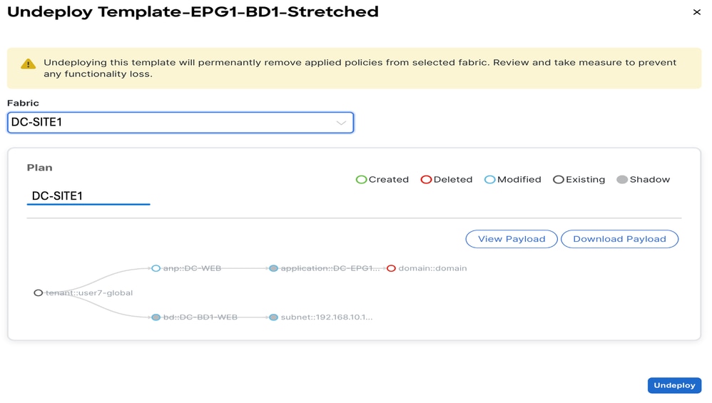
Figure 75: Choose DC-SITE1 and Click Undeploy
Dissociate Template-EPG1-BD1-Stretched from DC Site
This step dissociates the Template-EPG1-BD-Stretched from the DC Site.
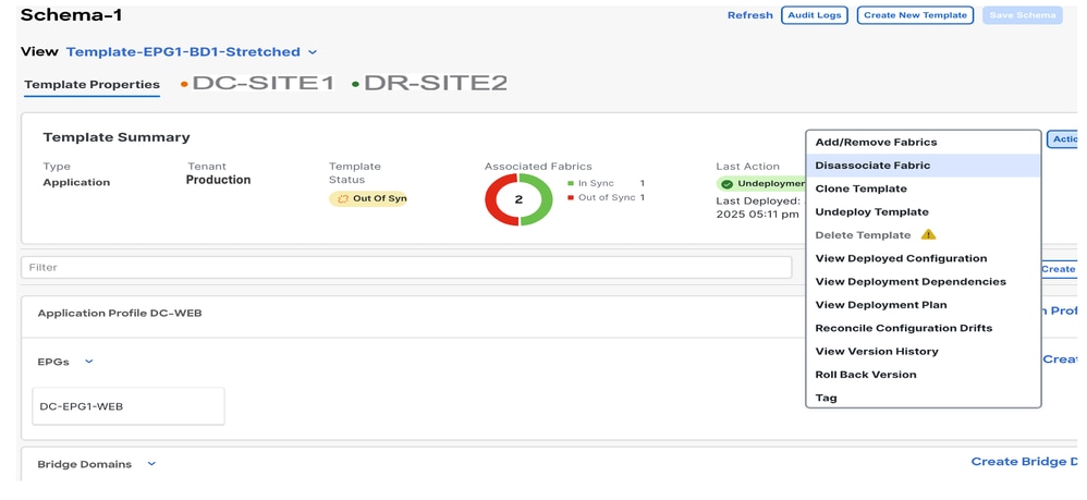
Figure 76: Click Dissociate Template
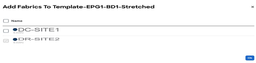
Figure 77: Uncheck DC-SITE1
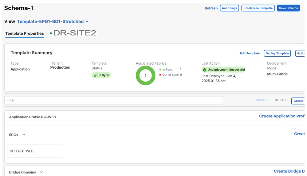
Figure 78: DC-SITE2 Part of Template-EPG1-BD1-Stretched
Logical Design after Undeploying the Template-EPG1-BD1-Stretched from DC
DC-EPG1-WEB and DC-BD1-WEB are not part of the DC Site after Undeploying the Template.
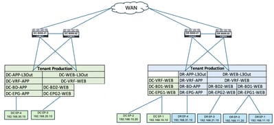
Figure 79: Logical Design after Undeploying the Template
Template-VRF-Contract-Site2 Creation
Template-VRF-Contract-Site2 created inside Schema-1. DR-SITE2 added to Template and Tenant-Production associated with the same Template. This is a site-specific template. This template is used in order to associate VRF and Contract from the DR site for DC-EPG1-WEB and DC-BD1-WEB.
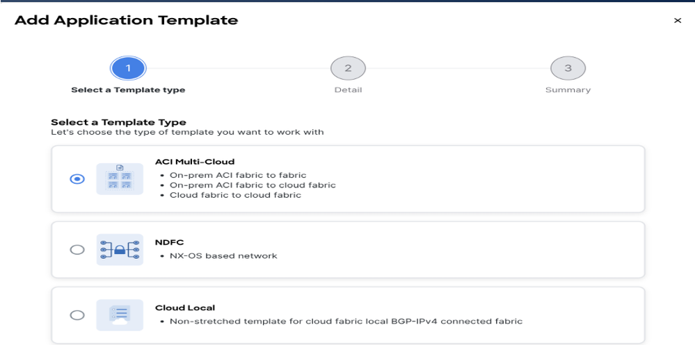
Figure 80: Add Application Template - Choose ACI Multi-Cloud
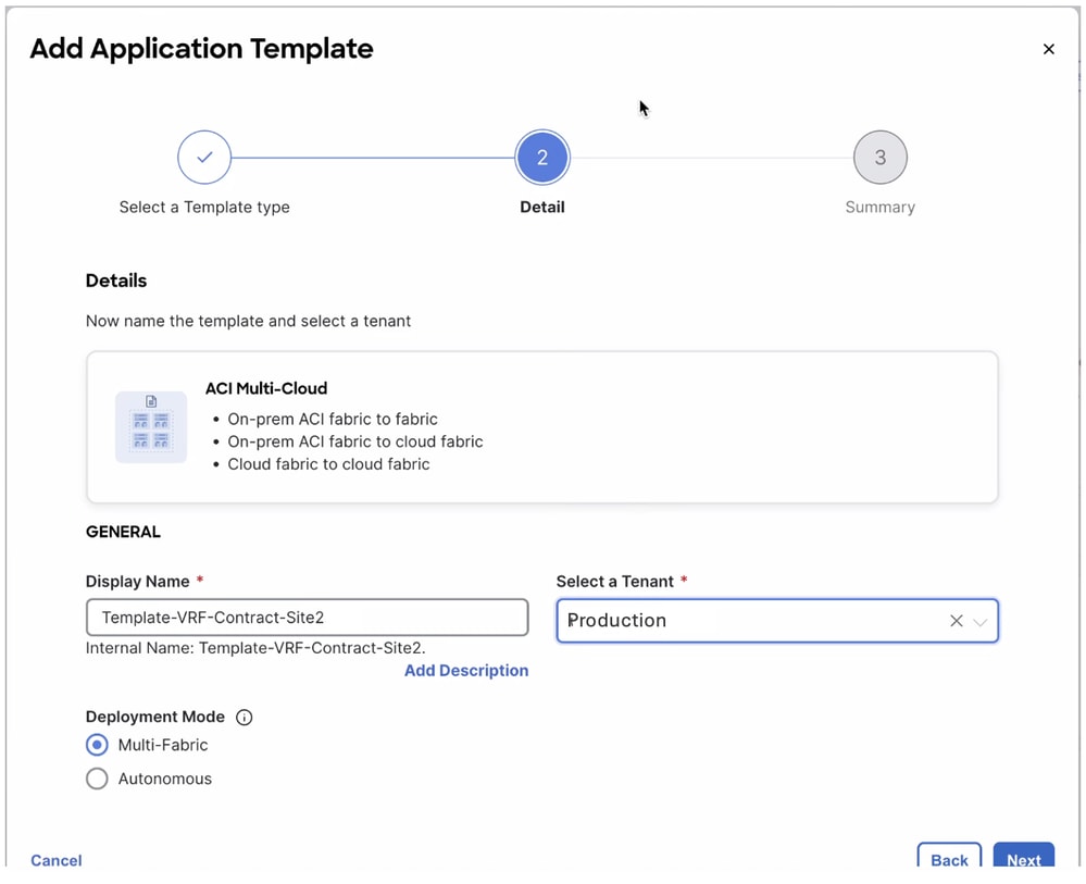
Figure 81: Add Template Name Template-VRF-Contract-Site2, Choose Tenant Production
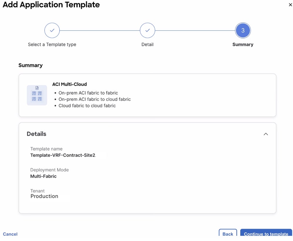
Figure 82: Template-VRF-Contract-Site2 Details
Import VRF-Contract in Template-VRF-Contract-Site2
Import DR-VRF-WEB and DR-VRF-WEB-Contract from DR-SITE2.
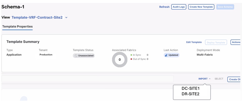
Figure 83:Click Import and Choose DR-SITE2
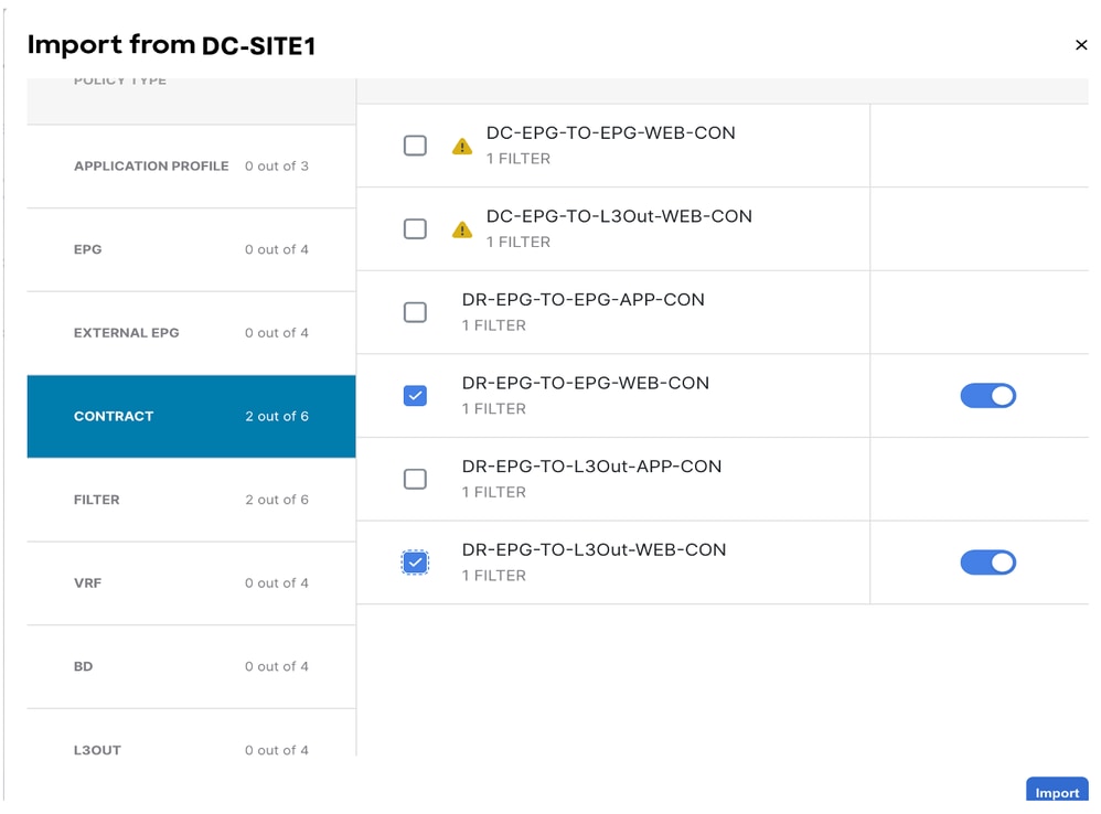
Figure 84: Choose Contract from DR-SITE2
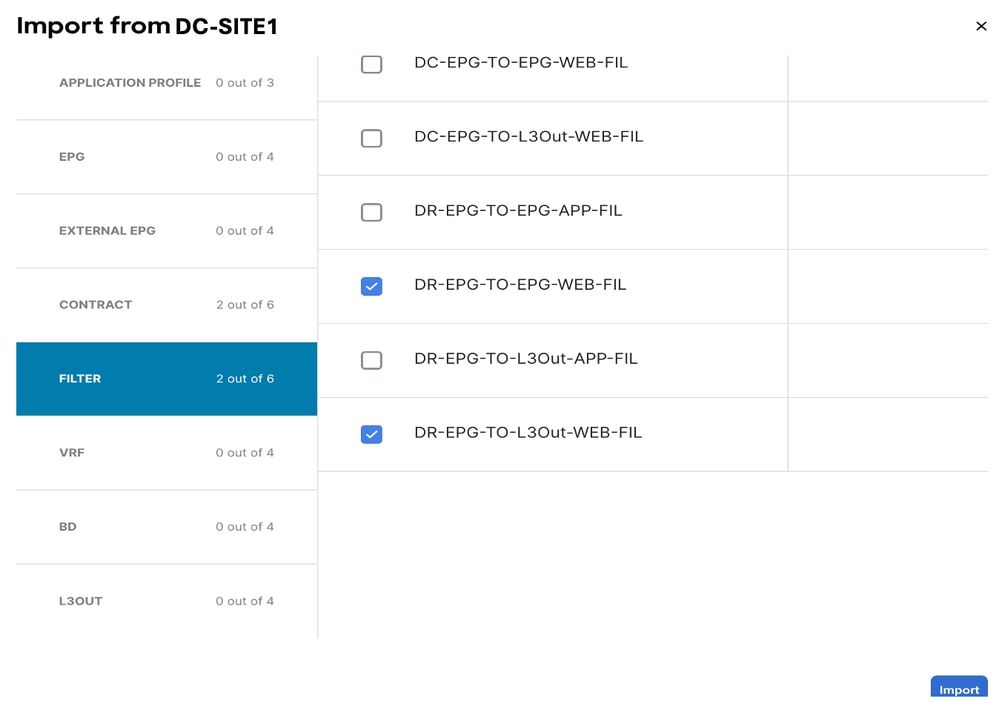
Figure 85: Choose Filter from DR-SITE2
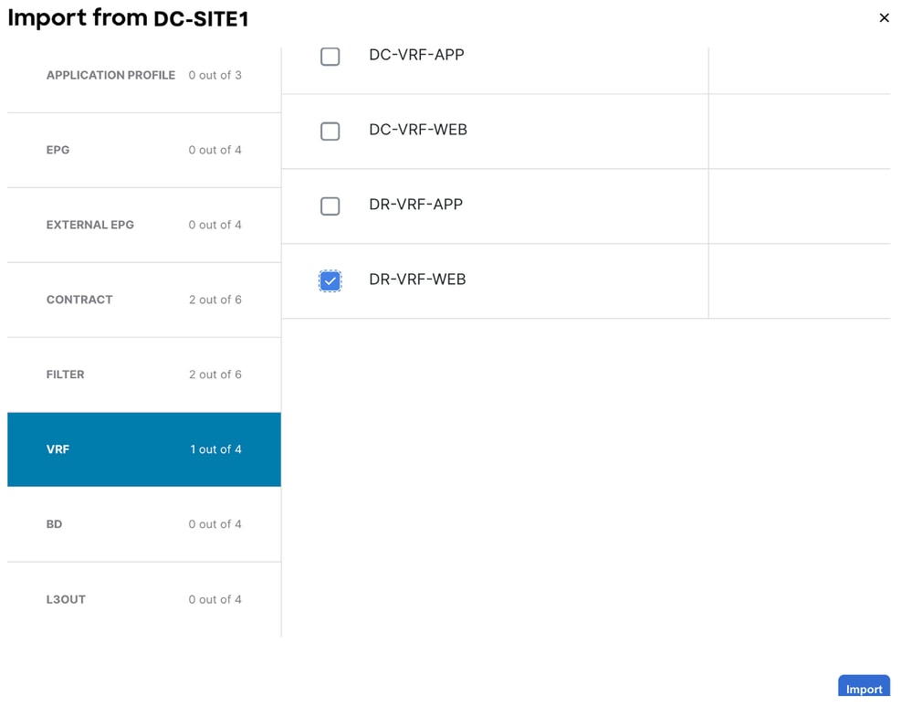
Figure 86: Choose VRF from DR-SITE2

Figure 87: Template-WEB-VRF-Contract-Site2 with VRF/Contract Information
Deploy Template-VRF-Contract-Site2
Click Deploy Template-VRF-Contract-Site2 and select DR-SITE2.
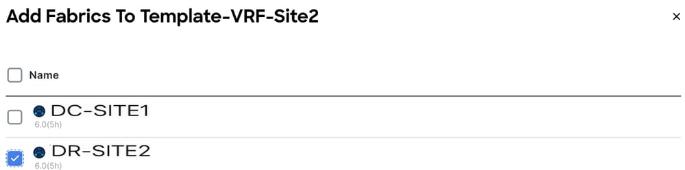
Figure 88: Add Fabrics to Template-VRF-Contract-Site2
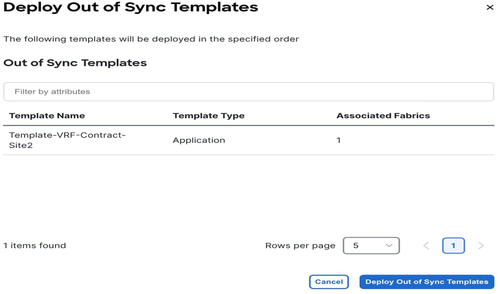
Figure 89: Deploy Out-of-Sync Templates
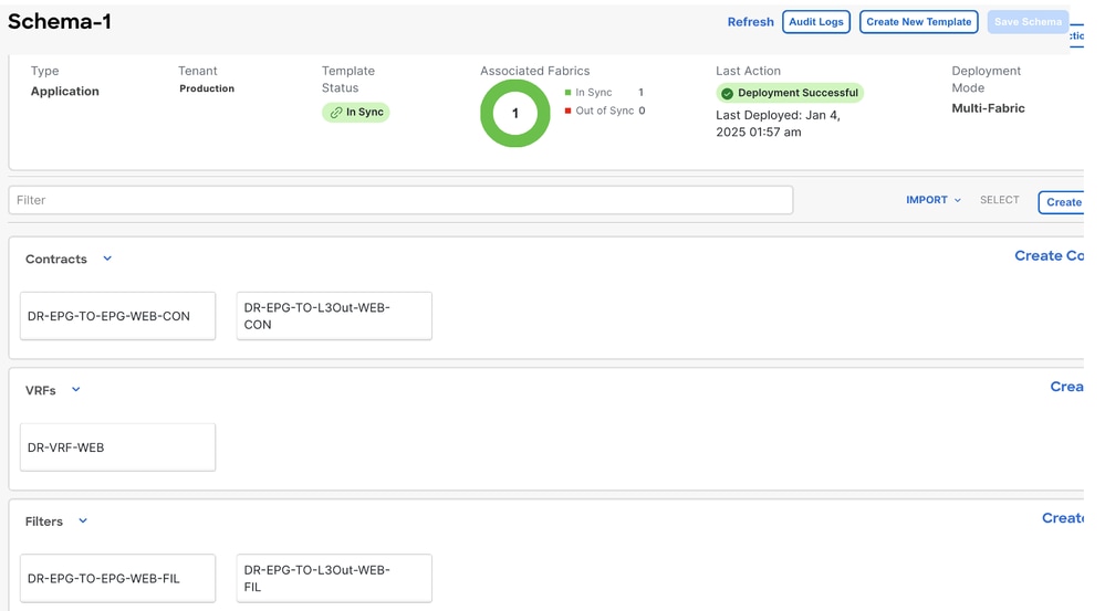
Figure 90: Deployment Completed
Associate DR-VRF-WEB to DC-BD1-WEB
Associate DR-VRF-WEB to DC-BD1-WEB from Template-EPG1-BD1-Stretched which was created earlier. DC-BD1-WEB is part of DR-SITE2.
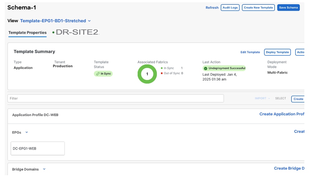
Figure 91: Click Template-EPG1-BD1-Stretched

Figure 92: Associate DR-VRF-WEB to DC-BD1-WEB
Apply DR-Contracts to DC-EPG1-WEB
Apply DR-Contract to DC-EPG1-WEB which uses DR contracts for the communication from DC-EPG1-WEB for Inter-DC, Inter-VRF, and Inter-EPG. DC-EPG1-WEB is part of DR-SITE2.
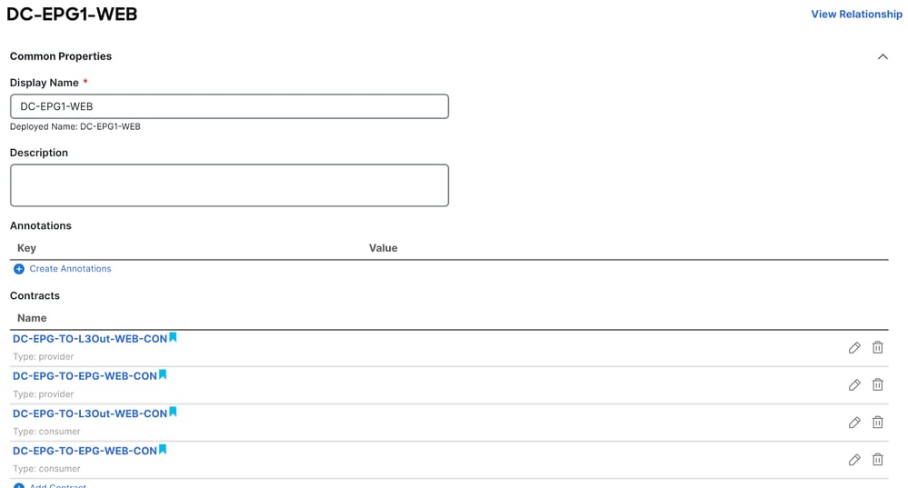
Figure 93: Delete DC-Contracts from DC-EPG1-WEB
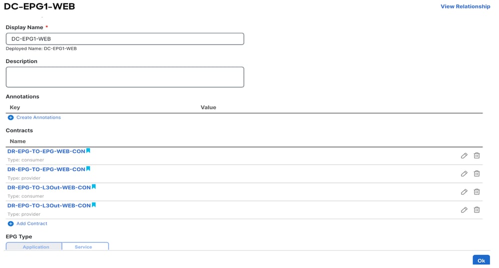
Figure 94: Add DR-Contracts in DC-EPG1-WEB
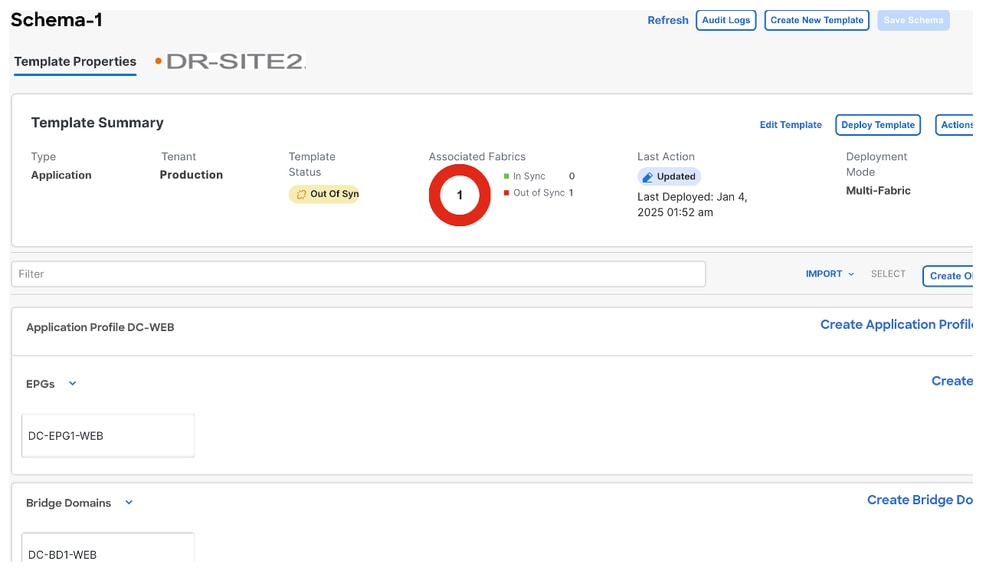
Figure 95: Template-EPG1-BD1-Stretched Information
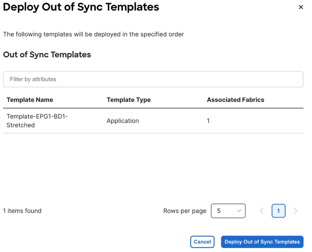
Figure 96: Deploy Out-of-Sync Templates
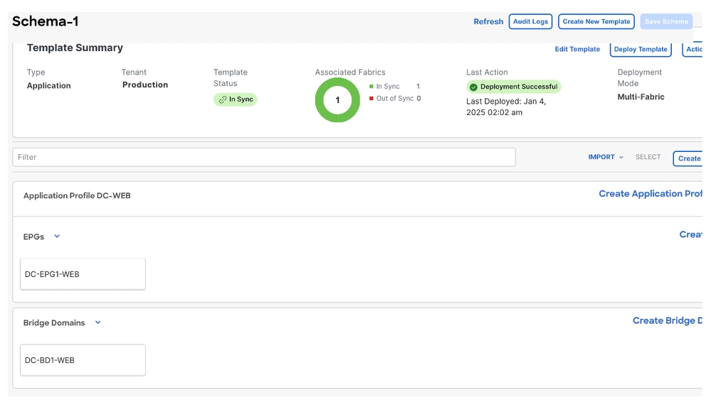
Figure 97: Deployment Completed
DC-Endpoint-1 Traffic Flow
DC-Endpoint-1 starts using DR-L3Out-WEB for communication with DC Endpoints. This communication requires necessary routing changes on WAN Switches.
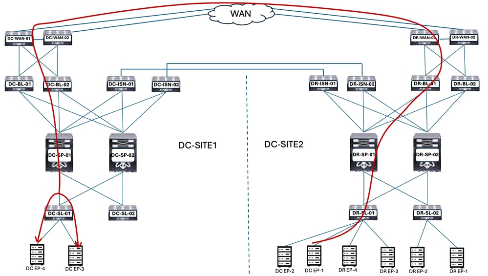
Figure 98: DC-Endpoint-1 Traffic Flow
Ping Response between DC-EP-1 and DC/DR-EPs
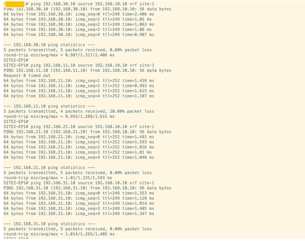
Figure 99: Ping Response between DC-EP-1 and DC-EP-2
Revision History
| Revision | Publish Date | Comments |
|---|---|---|
1.0 |
08-Jan-2025
|
Initial Release |
Contributed by Cisco Engineers
- Rajkumar GavandiCustomer Delivery Architect
- Manish MeshramCisco TAC Engineer
 Feedback
Contact Cisco
- Open a Support Case

- (Requires a Cisco Service Contract)