Introduction
This document describes the various methods to copy the software and the FAQs associated with the process of replacing the switch.
Problem
The switch does not load software due to a specific issue.
Solution
A few ways to work out a problem that helps the user to fix the issue are described in this document. This document also explores a few CLI commands that can be leveraged in order to confirm the booting process of the switch.
Methods to Copy The Software
A few methods that can be used to copy software to a switch are described here.
USB
A flash drive can be used to copy software in a switch. The user must format the flash drive with the FAT32 file system and then It can be used to copy software in the switch.
In general, all the flash drives are supported. If there is a challenge with the flash drive, it is better to check the datasheet of a given platform and check for any specific recommendations mentioned in that data sheet about the use of the flash drive.
Each switch has two flash drive slots. Use the dir command in order to check the slot number. Boot the code from the flash drive using the boot usb#:aci-image.bin (where # is the slot of the flash) command.
This command works in the loader prompt as well as in the switch prompt. In order to copy the software into boot flash, use the copy usb#:aci-image.bin bootflash command.
In this example, you see that flash slot 1 is used to connect and it is detected with image 14.2.4i code.
Sample output of loader > dir:
usb1::

 System Volume Information
 aci-image.bin

bootflash::

  CpuUsage.Log
  lxc
  disk_log.txt
  nxos.7.0.3.I7.3.bin
  auto-s
  libmon.logs
  .stats_pref.txt
  bios_bootup_scratch_not_cleared
Secure Copy (SCP) from APIC to Switch
Enable the SCP server feature and SCP services can be used to copy software from the Application Policy Infrastructure Controller (APIC) to a switch. Configure the management 0 interface with an IP address, and set up a default gateway for the management Virtual Routing and Forwarding (VRF) instance. Verify that pings work from management VRF to the APIC.
Configuration steps on Switch:
switch# configure terminal
switch(config)# interface mgmt 0
switch(config-if)# ip address ipv4-address{ [/length] | [subnet-mask]}
switch(config-if)# no shutdown
switch(config-if)# exit
switch(config)# vrf context management
switch(config-vrf)# ip route 0.0.0.0/0 default-gw-ip
switch(config-vrf)# exit
switch(config)# feature scp-server
switch(config)# exit
switch# copy running-config startup-config
Configuration steps on APIC:
admin@apic:~>scp /firmware/fwrepos/fwrepo/<aci-image.bin> admin@<node-mgmt-ip>:<aci-image.bin> where <node-mgmt-ip> is the management IP given on the switch.
Using External SCP/FTP/TFTP Server
This method is similar to the previous method but instead of copying the software from APIC, an external SCP/FTP/TFTP server must be used. Configuration steps remain the same except, the SCP service does not need to be enabled. Ensure that the ping works from the management VRF to the external server.
switch# configure terminal
switch(config)# interface mgmt 0
switch(config-if)# ip address ipv4-address{ [/length] | [subnet-mask] }
switch(config-if)# no shutdown
switch(config-if)# exit
switch(config)# vrf context management
switch(config-vrf)# ip route 0.0.0.0/0 default-gw-ip
switch(config-vrf)# end
Then copy the image from the external server to the switch using switch# copy tftp://tftpuser@<IP_TFTP>/path/to/aci-image.bin bootflash: vrf management.(Assuming the TFTP server is being used and IP_TFTP is the IP address configured on the TFTP server.)
Ethernet Out-of-Band Channel (EOBC) Method
This method allows booting from the primary over the EOBC channel. The full procedure to recover from this:
(i) Use the EOBC command from the loader on the secondary supervisor in order to boot this supervisor (SUP) over the EOBC from the primary.
(ii) Console to the secondary supervisor as admin. It is now in standby mode.
(iii) Transfer the image from the primary supervisor to the standby by copying it from /bootflash-remote/ to the boot flash using the command cp /bootflash-remote/<image> /bootflash/<Image>.
(iv) Run prepare-mfg.sh <image> in order to set up the supervisor and set the bootvars.
(v) Reload the standby supervisor from the primary in order to ensure that it comes up fresh from the image that was installed on its boot flash using reload module <module_number>.
This method must be used only when there is no other option available as it is very time-consuming.
loader > ?
?           Print the command list
boot        Boot image
dir         List file contents on a device
eobc        Booting image from active supervisorvia EOBC channel
help        Print the command list or the specific command usage
ip          Setting IP address or gateway address
reboot      Reboot the system
set         Set network configuration
show        Show loader configuration


loader > eobc
Finding driver for NIC vendor 8086 Device 1523
Found the device 8086:1523 at ioaddr e060, membase f0160000 at 1:0
Probing...igb: e1000_set_media_typeMedia type is serdes 005400c0
igb: e1000_set_media_typeMedia type is serdes 005400c0
igb: INTEL MAC. Link already up reset (ctrl 0x081c1a41)
Ethernet addr: 00:00:00:1C:00:00
igb: INTEL link status is 0x80280683
Link is up
Link speed = 1000 Mbps, Full Duplex
Useful CLI Commands during ACI Switch Recovery
Use this method when dealing with replacing a leaf switch or spine switch:
Step 1. Power on the new switch/supervisor and connect a console.
Step 2. Ensure that it is running the same Application Centric Infrastructure (ACI) code as in the fabric. If not, use any of the mentioned methods in order to copy software to the new switch/supervisor. Once the software is copied, employ these steps:
switch(config)# show file bootflash:aci-image-name md5sum
switch(config)# no boot nxos
switch(config)# copy running-config startup-config
switch(config)# boot aci bootflash:aci-image-name
switch(config)# reload
Step 3. From the new switch console, run the command setup-clean-config.sh. Reload (run the command reload) in order to clean up any configurations that already exist on the switch.
Step 4. Use these commands in order to verify the boot statements:
cat /mnt/cfg/0/boot/grub/menu.lst.localcat /mnt/cfg/1/boot/grub/menu.lst.local
Step 5. In case, the switch does not show correct boot statements, use this set of commands in order to clear out the old boot statements and set a new boot statement:
clear-bootvars.sh
setup-bootvars.sh <aci-image.bin>
Step 6. Proceed with commissioning the switch into the fabric. You can refer to this link.
FAQs Related to Recovery of The ACI Switch
Which method must be used to copy the software in the witch?
A. Four methods have been discussed in this document in order to accomplish this task.
If there are no restrictions in the data centers regarding the use of external laptops/flash drives/external servers like TFTP/FTP/SCP, then the flash drive method must be the one on your list. It is because it is very fast and efficient and saves users time and energy. If a user cannot use a flash drive in the data center, they must go for Method 2 or Method 3 depending on the restrictions in the data center.
Which software must be installed in the new leaf switch or Spine SUP?
A. Ensure that the new switch/supervisors are upgraded to the same software that is being used in the ACI fabric, otherwise, the leaf switch or spine supervisor remains stuck in the discovery process.
Can you upgrade/replace the spine switch without reloading?
A. If there is only one supervisor in a spine, then you cannot upgrade or replace it without reloading. There can be a production impact.
If there is a need to replace or upgrade the standby supervisor (in case of dual supervisor in a spine switch), then this procedure can be used:
(i) Plug in the NX OS supervisor in the standby slot and enter a break sequence (Ctrl-C or Ctrl-]) during the initial boot sequence in order to access the loader > prompt.
(ii) Plug the flash drive containing the ACI image into the standby supervisor flash slot.
(iii) Boot the ACI image.
How to replace both SUPs in the spine switch?
A. Step 1. Insert both the SUPs in the spine switch.
Step 2. Take the console access of each supervisor and check the code running on the SUPs.
Step 3. If it is NX OS, proceed with copying the intended ACI code in each SUP.
From an active supervisor connection only, you can use the commands:
copy flash1:aci-image.bin bootflash://sup-local
copy flash1:aci-image.bin bootflash://sup-remote
Step 4. Change the boot statements and verify the boot statements.
Step 5. Reload the entire chassis with the reload command. One more command to power cycle the switch (hard reboot) is /usr/sbin/chassis-power-cycle.sh.
Step 6. Verify that the spine switch is running on the intended code; you can then proceed with commissioning the switch into the fabric.
What to do if the Standby supervisor remains stuck in the 'inserted' state?
A. Copy a fresh copy of the software to the flash drive and boot the supervisor from the flash drive.
Copy the software to the supervisor and verify the boot statements.
Run the prepare-mfg.sh aci-image.bin command.
Verify in the GUI as well if the Standby supervisor starts showing over there.
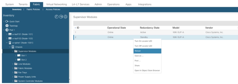
How does redundancy work in a spine switch with dual supervisors?
A. ACI Spine switch supports warm (stateless) standby where the state is not synched between the active and the standby supervisor modules. For an Online Insertion and Removal (OIR) or reload of the active supervisor module, the standby supervisor module becomes active, but all modules in the switch are reset because the switchover is stateless. In the output of the show system redundancy status command, warm standby indicates the stateless mode.
In order to test this redundancy, you can either execute a command system switchover from CLI or reload the active supervisor from GUI.
 Feedback