Low-Voltage PoE Lighting Design Guide
Available Languages
Bias-Free Language
The documentation set for this product strives to use bias-free language. For the purposes of this documentation set, bias-free is defined as language that does not imply discrimination based on age, disability, gender, racial identity, ethnic identity, sexual orientation, socioeconomic status, and intersectionality. Exceptions may be present in the documentation due to language that is hardcoded in the user interfaces of the product software, language used based on RFP documentation, or language that is used by a referenced third-party product. Learn more about how Cisco is using Inclusive Language.
- US/Canada 800-553-2447
- Worldwide Support Phone Numbers
- All Tools
 Feedback
 Feedback
This document provides a high-level overview of the design considerations for using Power over Ethernet (PoE) to deliver low-voltage lighting solutions and their control-related components. It provides guiding principles for installing and powering the endpoints, such as lighting fixtures and sensors, as well as the networking and computing requirements to manage the PoE solution.
The intended audience is all parties involved in purchasing, designing, and implementing a PoE solution using Cisco’s line of PoE switches, including:
● General contractors
● Project and/or account managers
● Mechanical, Electrical, and Plumbing (MEP) engineers and/or partners
● Low-voltage/AV designers
● Cable installers
● Supply vendors
Cisco manufactures and develops Power over Ethernet (PoE) solutions as a modern, agile, and sustainable alternative to connect, power, monitor and control PoE endpoints by providing up to 90 watts of low voltage DC power at the power source.
The 802.3bt standard increased the PoE wattage to encompass Class 5 through Class 8 devices that can use up to 90 watts, compared to the previous 802.3at standard– 30 watts and up to 60 watts with Cisco UPOE. These advancements in PoE have enabled new use cases such as PoE powered smart lighting, smart shades leveraging the same infrastructure equipment and practices as IT. In turn, IT personnel and building managers are now able to optimize the functionality, performance, and utilization of end devices by operating them only when needed, given conditions such as occupancy and daylight harvesting, using software and data-driven configurations. These capabilities help reduce consumption to achieve the goal of sustainability.
2. Low-Voltage Poe Lighting solution overview
A PoE solution requires Power Sourcing Equipment (PSE) that will provide the power to the Powered Devices (PD). These are devices that consume the power themselves or will in turn power additional devices connected downstream. Networking PoE switches, such as the Cisco Catalyst™ 9300 Series Switches, that can support a variety of PoE standards, ranging from 802.3at, which provides as little as 30 watts, up to 802.3bt, which provides as much as 90 watts per interface, are the heart of every PoE solution and will determine the use cases enabled by the solution.
Some advantages to having higher-wattage PSE include:
● Lower cost
◦ More wattage is available to power end devices, allowing them to be daisy-chained to a single gateway, reducing cable complexity and thereby reducing the cost of implementation.
● More available use cases
◦ Some end devices, such as lighting fixtures and motorized shades, may require higher wattage.
The PSE will deliver the power to the PD, but communications to and from them will also traverse through the PSE. Other considerations of the PSE’s and PD’s involvement in the PoE solution are discussed below.
2.1. Management of poe network and devices
All lighting manufacturers require a management suite to control and commission their system. Examples of advanced controls deliverable by these management suites include determining the operating parameters, such as light level and color temperature, based on conditions such as time, occupancy, and daylight harvesting. PoE manufacturers have their own requirements and practices for the management software to be installed and deployed on the network. The aforementioned requirements and practices should be adhered to upon consultation with the manufacturer. Summaries of the management solutions from major lighting vendors are given below.
● Molex’s PoE solution is managed by software installed on a Windows Server instance, which can be a virtual machine or a physical appliance. The hardware requirements should be met as recommended by Molex for the corresponding version and software desired.
● MHT’s Inspextor management software is installed on a Linux instance, which can also be installed on a virtual machine or a physical appliance and has its own hardware and network requirements.
● Platformatics has its own physical appliance that comes with the software, called Platformatics Area Controller (PAC), preinstalled. It needs to be connected to the network with two connections, one out-of-band connection to access the PAC and another connection to the PoE network. The PoE network needs to be isolated, so that the nodes and various PoE components can communicate only with the PAC, and other networks cannot reach the individual PoE nodes and components. The PAC also acts as the Dynamic Host Configuration Protocol (DHCP) server, so there are other networking and configuration considerations to be taken into account as well.
2.1.1. IP communication between the management solution and PDs
For the software to communicate with the gateways to receive and send data, the PDs will need to have IP addresses assigned to them, either statically or via DHCP. The client has the freedom to implement this as they see fit.
One example is per-port DHCP on Cisco® switches, where the switch acts as the DHCP server and assigns an IP address to any end device that connects to that particular interface. Another approach is to use an external DHCP server using the DHCP options that the PSEs support, such as option 82, which will add information to the DHCP request to properly allocate IP addresses from a pool on an external server.
As mentioned above with regard to Platformatics’ PAC solution, the PAC appliance itself will act as a DHCP server on an out-of-band network so that only the PDs will be able to communicate with the PAC for operations, but a user can log in to the PAC on a separate network to manage, configure, and monitor the PoE solution.
Last but certainly not least are the end devices themselves.
Many PoE vendors have published their endpoint offerings, and a sample of them can be found in the links below.
● Mecho Motorized Shade System products.
● Genisys PoE Lighting Systems products.
All PoE vendors offer devices that will connect to the PSE, deliver the power, and communicate with the various end devices in a PoE network. Vendors have a wide array of PoE end device offerings, but the common overlaps between them are:
● Devices to receive power from PSE and deliver to downstream devices.
● Manual controls and/or overrides for PoE end devices.
● Various sensors to monitor, control, or override the behavior and operations of PoE end devices.
● Modules to interface with devices from other PoE vendors to offer operational compatibility and integration.
With regard to lighting fixtures, some vendors manufacture their own fixtures to work seamlessly with their respective ecosystems, while others work with third-party vendors to manufacture fixtures that will work their PoE product stack. When obtaining services from third-party vendors, it is imperative that the fixtures meet the driver compatibility requirements outlined by the PoE vendors to ensure the safe and intended operation of said fixtures. The fixtures should ideally be tested with the driver connected to the PD to verify full operational functionality and compatibility.
2.3. Third-Party Equipment Compatibility
Regarding third-party interoperability and compatibility, many PoE vendors are aware that there are other aspects of an occupied space in addition to lighting that can integrate into a PoE network into an overarching Internet of Things (IoT) network that can communicate and enable powerful use cases for occupants.
Many vendors use REST APIs and BACnet to enable a slew of use cases that can all seamlessly integrate into a single IoT solution, rather than being isolated and managed independently. These solutions reduce complexity and deployment requirements.
Sensors from different vendors can be used to interface with and control lights, shades, Heating, Ventilation, and Air Conditioning (HVAC), and other aspects of the occupied space so that different products from other vendors can be used to monitor and modify the operations of an environment. There will undoubtedly be PoE deployments in which one vendor does not have all the solutions to meet a client’s requirements, but enabling all the systems to communicate using REST APIs and BACnet will allow for a very robust PoE deployment.
This section displays sample floor plans of PoE low-voltage lighting solutions from various manufacturers, showing how the PSEs connect to the PDs and downstream end devices using the various connections and products offered by different vendors. Different vendors have varying methods and philosophies on how to power the downstream end devices connected to the PD, and the floor plans shown here seek to exhibit those methods and philosophies.
3.1. Simplistic Molex Sample Deployment
A simple diagram of a sample PoE solution can be found below.
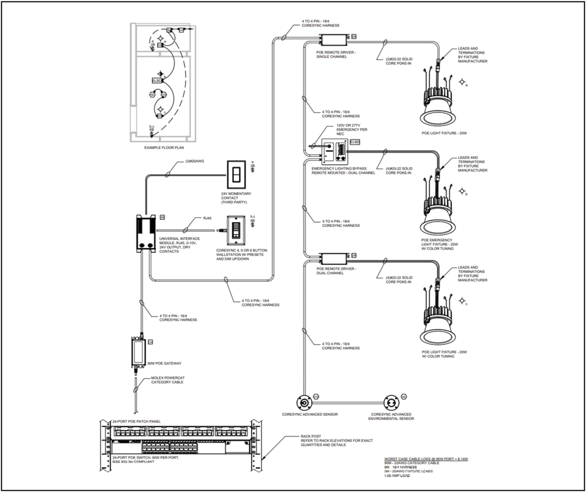
Simple Molex deployment
In the diagram above, a powered category cable connection to a PSE goes to the 90W gateway, which connects to a universal interface module that further branches out to the following connections:
● Momentary contact wall switch, through 20-gauge cables.
● Molex CoreSync wall switch, through an RJ-45 cable.
● Remote single-channel PoE driver, through a 4-pin Micro fit CoreSync harness.
The remote PoE driver powers a downlight but is also daisy-chained to an emergency lighting bypass, which also has a driver powering another downlight.
The bypass is again daisy-chained to a remote dual-channel PoE driver that powers the third downlight. The PoE driver is also daisy-chained to a CoreSync advanced sensor, which daisy-chains to the final device, the CoreSync advanced environmental sensor.
3.2. Robust Molex Sample Deployment
A more robust sample diagram of a PoE solution can be found embedded below.
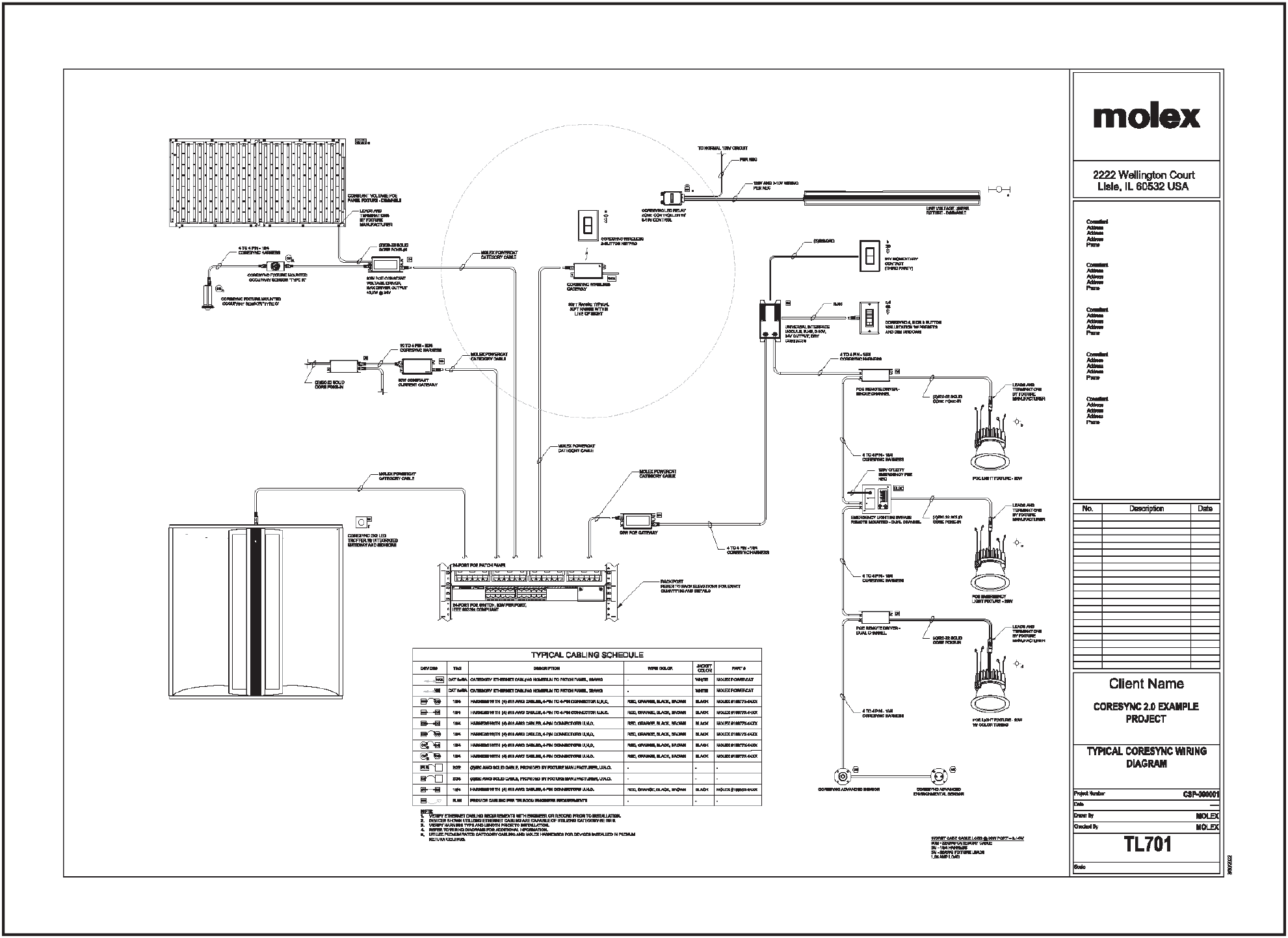
Robust Molex deployment
The deployment shown above has five connections originating from the PSE out to the following devices:
● -CoreSync 2x2 D troffer
● 60W constant current gateway
● 60W constant voltage gateway
● CoreSync wireless gateway
● 90W PoE gateway
The first category cable providing power connects to a 2X2 LED troffer using an RJ-45 Ethernet connection to a gateway that’s embedded into the fixture, which also has sensors.
The second category cable providing power connects to a 60W constant voltage gateway connected to a driver that daisy-chains out to other end devices as well as powers a light fixture through the poke-in connection.
The third category cable connects to a 60W constant voltage driver that uses a 4-pin Microfit connection to a CoreSync fixture-mounted occupancy sensor, which further daisy-chains via a 4- pin Microfit connection to another CoreSync fixture-mounted occupancy sensor. A second connection off the PoE driver connects to a panel fixture via a 2-conductor solid-core poke-in.
The fourth category cable connects to a CoreSync wireless gateway to communicate with a wireless 2-button keypad that can be mounted anywhere in the space within range of the gateway.
The fifth and final category cable goes to a 90W PoE gateway that connects to a Universal Interface Module that connects to a third-party 24V momentary contact. A second connection is made via an RJ-45 connection to a CoreSync wall switch.
A third connection from the module daisy-chains to a PoE single-channel driver that has a 2-conductor poke-in connection to a downlight.
Another daisy chain is established to an emergency lighting bypass that has another 2-conductor poke-in connection to an emergency downlight, with another daisy chain to a dual-channel PoE remote driver that connects through a 4-conductor poke-in to the last downlight in this deployment.
The dual-channel driver daisy-chains to a CoreSync Advanced Sensor via a 4-pin Microfit connector, and the last daisy chain is established to the last end device, which is the CoreSync Advanced Environmental Sensor.
3.2.1. Downstream end device connectivity
Molex adopts a daisy-chain philosophy when connecting the PoE end devices to the PD. Most, if not all, of Molex’s end devices have an input connector to receive power and an output connector to send power downstream to additional devices. Molex uses 4-pin Microfit connectors to connect the end devices back to the gateway to distribute the power from. Molex has guidelines that provide best practices and limitations regarding their use, and they should be adhered to upon consultation and verification.
A sample deployment for a PoE solution that could be in a college dormitory, with a sample floor plan, is pictured below.
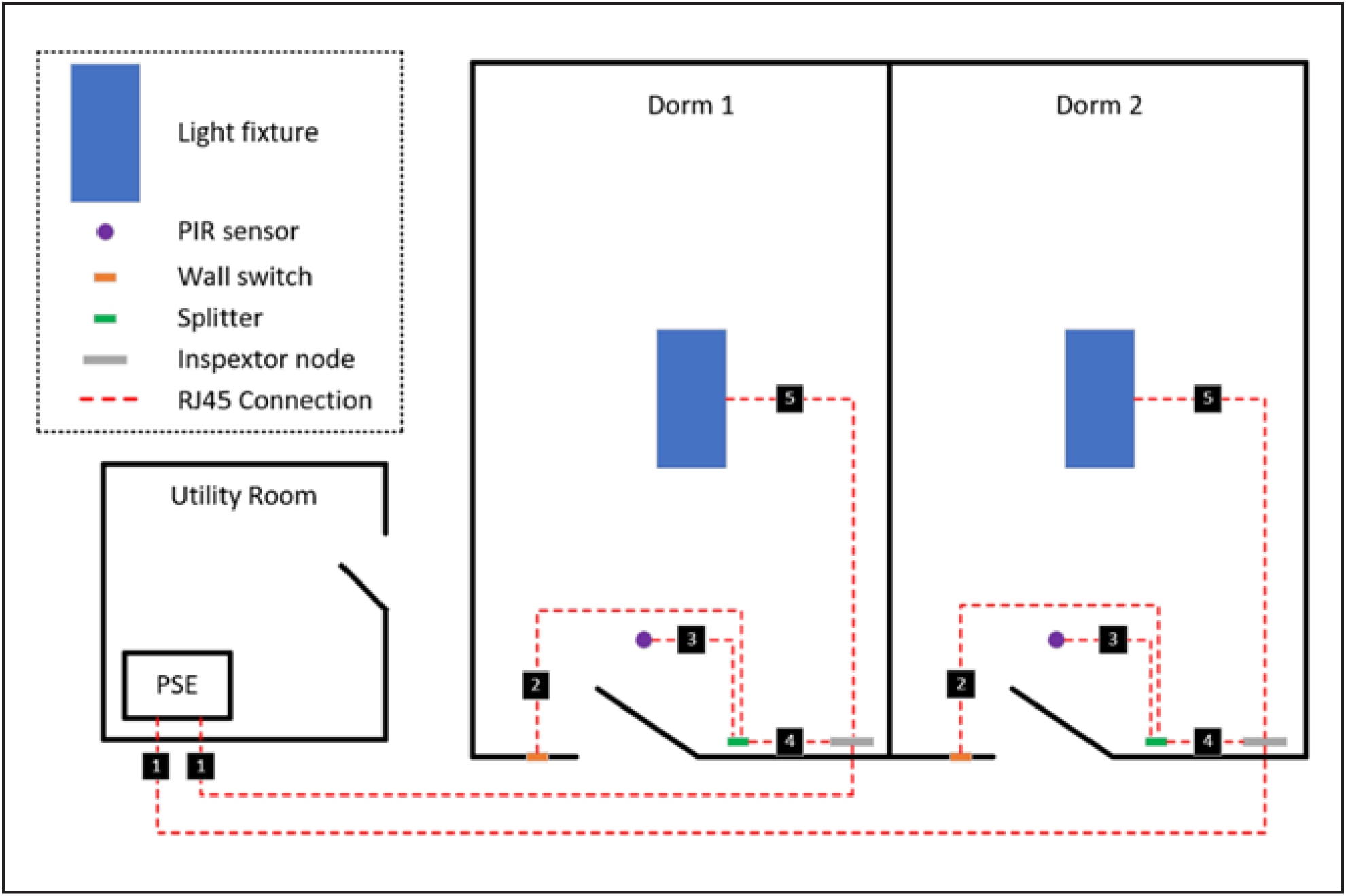
Sample MHT deployment
Table 1. MHT deployment connection description
| Connection no. |
Originating device |
Terminating device |
Description |
| 1 |
PSE in utility room |
Inspextor node |
Category cable from PSE to Inspextor node to power PoE devices |
| 2 |
Wall switch |
Splitter |
Wall switch connected to any interface on splitter output, to receive PoE from node |
| 3 |
Passive infrared (PIR) sensor |
Splitter |
PIR sensor connected to any interface on splitter output, to receive PoE from node |
| 4 |
Inspextor node |
Splitter |
Controls interface on Inspextor node connected to input on splitter, to allocate power from node to devices connected to splitter |
| 5 |
Inspextor node |
Light fixture |
Luminaire interface on Inspextor node connected to whips on light fixture to provide power |
The deployment above would place a PSE in the utility room of each floor. Each dorm room has the following devices
● Light fixture
● PIR sensor
● Wall switch
● Splitter
● Inspextor node
Each Inspextor node would have a single RJ-45 category cable connecting back to the PSE in the utility room to receive the power. The Inspextor node would then distribute the power as necessary to the single light fixture connected to a luminaire interface on the node and the splitter, which would further allocate the power as necessary to the PIR sensor and wall switch.
The deployment above would accommodate as many powered category cable connections as the PSE could support to each dorm room. So a device such as a Cisco Catalyst 9300-24H, which has 24 onboard RJ-45 Cisco UPOE+ interfaces, could support up to 24 dorm rooms with the following considerations:
● The Inspextor node can supply ample power to all devices connected.
● The PSE has a large enough power supply to power all nodes connected.
3.3.1. Downstream end device connectivity
MHT’s architecture to power downstream end devices is to use splitters. Unlike Molex, which has an input and output connector using 4-pin Microfit connectors, MHT’s PoE devices will generally have a single RJ-45 connection to power the device. So using the splitter, MHT adopts a star topology in which a splitter receives the power from the PD to power the other end devices connected to it.
3.4. Sample Platformatics Deployment
A sample deployment for the same dorm room use case using Platformatics can be found below.
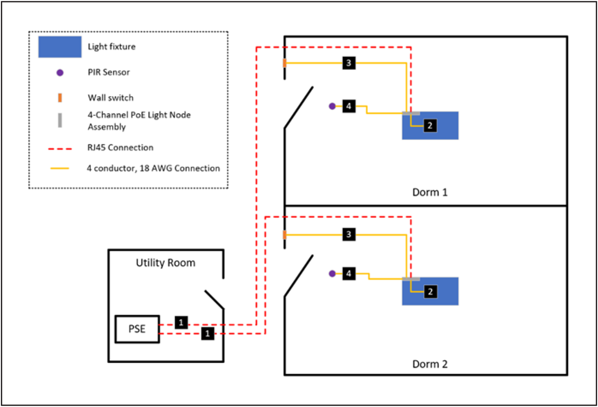
Sample Platformatics Deployment
Table 2. Platformatics deployment connection description
| Connection no. |
Originating device |
Terminating device |
Description |
| 1 |
PSE in utility room |
PoE light node assembly |
Category cable connection from PSE to 4-channel node to power PoE devices |
| 2 |
PoE light node assembly |
Light fixture |
Connection from node to light fixture to provide power |
| 3 |
PoE light node assembly |
Wall switch |
Connection from node to wall switch |
| 4 |
PoE light node assembly |
PIR sensor |
Connection from node to PIR sensor |
The deployment above would place a PSE in the utility room of each floor. Each dorm room has the following devices
● Light fixture
● PIR sensor
● Wall switch
● PoE light node assembly
Each PoE node would have a single RJ-45 category cable connecting back to the PSE in the utility room to receive the power. The node would then distribute the power as necessary to the PIR sensor (occupancy), wall switch, and lighting fixture through a 4-conductor 18 AWG cable connected via screw-down terminals.
The deployment above would accommodate as many powered category cable connections as the PSE could support to each dorm room. So a device such as a Cisco Catalyst 9300-24H, which has 24 onboard RJ-45 UPOE+ interfaces, could support up to 24 dorm rooms with the following considerations:
● The node can supply ample power to all devices connected.
● The PSE has a large enough power supply to power all nodes connected.
3.4.1. Downstream end device connectivity
Platformatics also adopts a star topology architecture when powering end devices connected to its PDs, but rather than using a splitter, it has multiple channels on the PD that will connect directly to the end devices and power them in a more direct fashion. The end devices will determine which type of cable to use, whether 2-conductor or 4-conductor with various gauges. Consult Platformatics’ product pages to determine the type of cable to use to connect the end devices back to the node assembly.
The spaces where the PSE will be stored will require cooling in order to maintain safe and proper operations. It is important to note that due to voltage loss, the wattage consumed will be higher at the PSE than at the PD, and the standard power draw to turn the PSE on should also be considered when providing cooling to the space, whether it is at the Main Distribution Frame (MDF) or Intermediate Distribution Frame (IDF).
Some PSEs have passive cooling, since they are designed to be deployed in spaces such as plenums and do not necessarily require active cooling to maintain recommended operational parameters.
Due to the innovations being made in PoE technology, we recommended designing the cooling infrastructure for scalability to accommodate additional cooling in the future should the PoE deployment grow in scope and design. The cooling design should also address redundancy and fault tolerance possibilities by having backup solutions such as secondary cooling so that the PSE can remain operational should any problems arise with the cooling solution.
An important consideration is that in the deployments that Cisco has been involved in, the traditional method of calculating cooling capacity requirements did not have to be applied. The main calculation to consider is the residual wattage that does not get consumed and used by the PoE components of the solution. An example calculation is in the following section.
The total wattage used by the power supplies on the PoE switches does not need to be calculated into the cooling requirements. This is because the heat they generate does not entirely need to be cooled. This section describes an example calculation of the cooling required by a 24-port interface running at the maximum supported 90 watts.
All 24 ports operating at 90 watts will consume 2160 watts.
This should then be divided by the power efficiency of the power supply, which in this case will be assumed to be 90%, so we divide 2160 watts by the 0.9 power efficiency rating, for a total of 2400 watts generated by the PoE solution.
We then calculate the difference in wattage between what is being pulled from the outlet to the PSE and what is being consumed by the PoE end devices. This would be 2400 watts – 2160 watts, or 240 watts.
The 240 watts would be in addition to the wattage necessary to power the switch itself, which, for the sake of example, will be calculated as 200 watts, and this should also be divided by the 90% power efficiency rating, amounting to 222 watts.
Thus, the heat load of a 24-port interface using 90 watts, with an operational power draw of 200 watts and a 90% efficient power supply, would be 462 watts. To calculate the amount of cooling required, we convert this wattage to BTU, with 1 watt equal to 3.412 BTU/hr. The result is 1576.34 BTU of cooling recommended for each switch, assuming that all interfaces will be consuming 90 watts.
Table 3. Sample calculation of cooling requirements
| Watts drawn at interface * Quantity of interfaces = Total wattage of PoE devices |
| 90 * 24 = 2160 |
| Total wattage of PoE devices / Power efficiency of power supplies on switch = Wattage of PoE devices from PSE |
| 2160 / 90 = 2400 |
| Wattage of PoE devices from PSE – Total wattage of PoE devices = Residual wattage of PoE devices |
| 2400 – 2160 = 240 |
| Switch operational power / Power efficiency of power supplies on switch = Switch operational power from wall |
| 200 / 9 = 222 |
| Residual wattage of PoE devices + Switch operational power from wall = Wattage to cool |
| 240 + 222 = 462 |
| Conversion of wattage to cool to BTU = Required cooling capacity |
| 462 * 3.412 = 1576.34 |
Cabling serves as the backbone of the power delivery to the PDs deployed throughout a PoE deployment, and certain considerations should be taken into account when designing the runs.
● Structured vs. unstructured
◦ Bundle size of runs
● Bandwidth of communication traversing the cables
● Wattage being delivered to PD
● Distance from PSE to PD
● Location and space cables will be run through
◦ Indoor vs. outdoor
◦ Plenum vs. nonplenum
● Cost of cables
Many jurisdictions have standards and regulations regarding low-voltage cabling, and these will be the ultimate guidelines to follow. When guidelines, standards, and regulations are not the most up to date, we strongly recommend following BICSI (ANSI/BICSI N1-2019) and IEEE (525-2007) standards for cable installations, whichever are the most stringent guidelines applicable to the PoE deployment.
Due to the ever-evolving nature of PoE and the innovations made in PoE technology, as with the cooling solution, a good practice is to permit flexibility and utility so as to be able to leverage the existing cabling infrastructure to enable new use cases and deploy new PoE products. This practice should also be adhered to when designing the infrastructure and determining the specifications for the cables.
When designing the runs from the PSEs to the PDs, bundling will be largely determined by the type of cable used. Parameters such as amperage, temperature, exposure to elements, and other standardized criteria for which there are ratings will determine the type of cable to use, but bundling will largely be determined by standards and regulations. Various parties, whether they be the cable manufacturers, the PoE manufacturers, or even local jurisdictions, will all have guidelines that must be adhered to in order to be in compliance and maintain safe and effective operating conditions.
IEEE standards for PoE cables are written with 100-meter cable limitations in mind. The PDs will also be supported by the manufacturer with the understanding that the cabling infrastructure will meet the IEEE standards, and the manufacturer will not support devices and deployments that are in violation of those standards. Even if the jurisdiction standards and regulations were to permit cabling infrastructure with longer cable runs, the devices have been manufactured to meet the IEEE standards, so the infrastructure should be designed accordingly.
Having said that, the standards are written for the worst-case scenario. The expected wattage after 100 meters from a 90-watt interface is 71.3 watts. However, under certain circumstances, such as ideal cables like 22-gauge from end to end, shorter cables, and ambience, the actual wattage will be significantly higher than 71.3 watts, and the PoE solution can be designed to support closer to the 90 watts coming out of the PSE. In anticipation of such events, different PoE manufacturers have several tools available that will aid in calculating the length of the various cables used in their PoE solution.
5.1. Placement of PSEs
The placement of PSEs will primarily be determined by the distribution and deployment of end devices throughout the physical space. Keeping in mind the IEEE standards, which are specified to a maximum length of 100 meters, the PSEs, whether located in an MDF, an IDF, or even a plenum, should be placed so as to best accommodate the needs of the client.
The goal is to ensure that the powered category cable connections back to the PSE can supply all the necessary wattage to the PDs. The following table lists the expected wattage of varying lengths of PoE-optimized 22-gauge cables.
Table 4. Expected PoE wattage for various cable lengths
| Cable length (m) |
15 |
40 |
80 |
100 |
| Expected wattage (W) |
88 |
87 |
84 |
83 |
It is important to note that even though the cable itself is capable of minimizing voltage loss and carrying the wattage stated in the table above, not all PDs are designed to distribute all the wattage that is available to them. Some vendors will cap the wattage available to the end devices connected to the PD at the 71.3 watts stated in the IEEE standard, while others will permit the wattage in excess of 71.3 watts to be fully used by the connected devices.
Resilience must be addressed due to the nature of the utility that a PoE solution provides. Events such as natural disasters and circuitry faults can be incredibly disruptive, and these concerns must be addressed, whether for reasons such as to comply with fire and hazard regulations or just simply to maintain day-to-day operations. A PoE solution can provide resilience in several ways, but the fundamental idea is to maintain power to either the PSE or the PD. A PSE can retain its power through a variety of options, which again will be dictated by regulations and guidelines permitted by the jurisdiction, but such options include inverters, uninterruptible power supplies, and buffer modules.
The main idea is to have an alternative power source come online almost instantaneously in the event that the power delivered to the power supplies on the PSEs is cut off. Again, standards and regulations will determine which method will be viable and permitted to meet the needs of each individual use case, but storing the energy that will be provided to the PSEs and making it available upon necessity are the paramount principles in effect.
Certain PoE manufacturers have their own product offerings to meet UL924 safety standards, such as Molex’s CoreSync Emergency Lighting Bypass and Platformatics’ PoE Emergency Light Node Assembly. These modules are compliant with several standards to meet operational and safety requirements in the event of an emergency that requires the PoE components to be online when the PSEs are not available. The installation, operation, specifications, and additional details can be found in the links above.
6.1. Emergency Lighting Considerations
Again, regulations and guidelines set forth by the jurisdiction in which a PoE solution will be deployed will determine the feasibility of an emergency lighting use case, but the factors to address include:
● Duration of operational uptime
● Minimum lumens to be provided to specified square footage
● Disabled controls
The bypass developed by Molex seeks to address the concerns listed above as well as others, and again, specifics can be found on the product page.
7. Power Sourcing Equipment Selection
Powered devices are designed to serve a variety of use cases, but to take full advantage of their robust features, the devices that will power them must meet certain requirements.
In order for the PDs to communicate with their respective management equipment, they require IP communications and, as such, will need to be assigned individual IP addresses, either statically or via DHCP. Certain PoE vendors allow the clients the freedom to assign the IP addresses statically or dynamically as they see fit, while others have other recommendations and/or requirements, and the vendors should ultimately be consulted to enable the IP communications on the devices.
Certain use cases such as basic lighting can operate right out of the box without any communication with their respective management software, but it’s best not to assume that this will be the case. Again, to take advantage of the full features of the PoE solution, IP communication will always be desired for remote management and feature-complete operations.
7.2. Power Availability At Interface
PDs come in a variety of configurations. They have a range of wattages in configurations such as constant voltage or amperage, may be equipped with a wireless antenna to receive communications wirelessly, and many more variations. All these features, however, are useless without the proper PSE to meet the requirements of the devices. It is important to ensure that the PSE is able to deliver the necessary wattage as well as to send and receive communications to make full use of its capabilities.
When implementing PoE solutions, several parties will be involved. A sample responsibility table is given below.
Table 5. Sample roles and responsibilities for implementing a PoE solution
| Roles |
Responsibilities |
| Architect |
Provides floor plan backgrounds and reflected ceiling plans |
| MEP and telecom engineers |
Provide lighting layouts, network rack layouts, and raceway requirements |
| Lighting designer |
Provides luminaire schedule compatible with CoreSync driver requirements |
| Lighting technology consultant |
Designs PoE lighting system |
| Contractor |
Acquires and installs raceways and cables |
| Sales representative |
Serves as an advisor to oversee implementation |
| Lighting distributor |
Ensures that PoE requirements are met, provides shop drawings, and delivers fixtures to site |
| IT distributor |
Provides IT equipment such as network devices and racks |
| Systems integrator |
Installs, verifies, and commissions PoE lighting systems |
Cisco has published case studies describing how customers have successfully implemented low-voltage PoE solutions for powering lights, automated shades, environmental controls and monitoring, and other use cases, with profound and powerful results.
The case studies for Cisco Penn One Plaza, Norfolk Southern, WPP, and others can be found at the respective links.
Smart buildings and PoE technologies have been implemented in sites with great success to encourage a productive, welcoming, safe, and comfortable environment for workers to return after the pandemic. This was all achieved in conjunction with promoting sustainability by better utilizing resources when needed and reducing consumption when and where possible. Data-driven configurations using software to control the behavior of end devices is a powerful benefit of PoE lighting solutions.
Type 4 802.3 bt standards have enabled up to 90 watts to be available on a PoE switch, using a single cable to provide power and communicate with PoE devices, which now include lighting use cases.
PoE vendors and manufacturers are constantly advancing the technology to power not only phones, cameras, access points, and other end devices traditionally associated with PoE, but also lights, shades, workstations, security devices, and many more to come.
Low-voltage circuits associated with PoE also reduce or eliminate the dangers, materials, and limitations associated with high-voltage circuits. In the past, the placement and uses of electronics were determined primarily by the location of power sources such as outlets, but with the flexibility and scalability of PoE, electronics can now be placed and used in a variety of locations, so long as a category cable can be installed to it.
Creativity and imagination will allow systems to be integrated into a single-pane-of-glass solution to monitor and configure a variety of aspects of occupied space, rather than being managed as isolated environments and solutions, as they were in the past.
Due to the intelligent negotiations and power distributions that occur from PSE, the end devices can also be protected from electrical anomalies such as overloads or underpowered scenarios.
To meet sustainability goals, PoE technology will play a huge role in optimizing resource utilization and reducing resource consumption.