Cisco Secure Access Services Edge (SASE) Deployment Case Study
Available Languages
Bias-Free Language
The documentation set for this product strives to use bias-free language. For the purposes of this documentation set, bias-free is defined as language that does not imply discrimination based on age, disability, gender, racial identity, ethnic identity, sexual orientation, socioeconomic status, and intersectionality. Exceptions may be present in the documentation due to language that is hardcoded in the user interfaces of the product software, language used based on RFP documentation, or language that is used by a referenced third-party product. Learn more about how Cisco is using Inclusive Language.
This is a deployment case study that provides a technical review of an implementation of the Cisco Secure Access Services Edge (SASE) architecture. Cisco’s SASE architecture combines SD-WAN, cloud security, zero trust network access, and observability to deliver seamless, secure access to applications, anywhere users work. For more information on Cisco’s SASE architecture visit cisco.com/go/sase.
To elucidate how the customer goals of reducing cost, improving user experience, and minimizing risk were addressed, we will present a case study illustrating lessons learned from designing and implementing a large-scale digital transformational project using a SASE architecture framework. It serves as an introduction for those who want to design and implement Cisco SASE components, while operating and managing the consumer/provider exchange point. The paper also explains the main building blocks and addresses field deployment key tenets.
The solution encompasses the Cisco SD-WAN fabric and Cloud on Ramp, integrated with Cisco Umbrella Secure Internet Gateway (SIG) and other Cisco offerings, to provide secure and optimize interconnect for distributed enterprises users with applications hosted in private data centers, and various public clouds.
This project was designed and delivered by a Cisco Customer Experience (CX) team bringing to bear skills, experience and tools to design and deploy multiple Cisco platforms for a key global customer successfully, and on time. This white paper is a guide for how you can do that too.
The global scale of the project covers four global locations located in the Americas, EMEA, APAC, and China.
This customer acquired space and circuits at Collocation Neutral Facility (CNF) located in San Jose, Virginia, Amsterdam, Frankfurt, Hong Kong, and Singapore.
The first phase of the project is designing and deploying a customer managed global backbone to interconnect the CNFs. One of the key business motivators is lowering the OPEx cost that was inherited from the SP operated global core. Cisco CX designed and deployed a redundant fiber ring backbone that utilizes the Cisco NCS-5000 platform. Cisco implemented an MPLS Segment Routing (MPLS-SR) feature set, for which IOS-XR provides segmentation and intelligent traffic engineering for transient backbone IP traffic.
Regional CNF was designed as the headend (or hub) for SD-WAN overlay fabric. Every regional headend consists of SD-WAN Cloud on Ramp for Colocation (CoRC) hardware and software stack (Cluster).
CoRC acts as a secure Multicloud “patch panel” between the enterprise consumers, and applications cloud providers. Customers can deploy virtual network and security services at the CNF based on business demands within minutes, with simplified and centralized orchestration, management, and operations.
The second phase of the project delivers design and implementation of an SD-WAN virtual headend service group that is hosted in the regional CoRC cluster. The SD-WAN service group consists of a pair of Cisco Virtual Network Function (VNF) routers configured in SD-WAN mode.
The virtual headend service routing group provides resilient control plane connectivity between the customer’s regional sites and multi-clouds such as data centers.
The Cisco CX team also deployed and integrated Cisco Umbrella with customer on-premises security hosted solutions. Umbrella provides cloud-delivered security, interactive threat intelligence, and secures SD-WAN Direct Internet Access (DIA) and enterprise end -point remote access. Umbrella is Cisco's cloud-based, combines secure web gateway (SWG), cloud-delivered firewall (CDFW), DNS-layer security, and cloud access security broker (CASB) functionality in a single cloud security service. Umbrella prevents malware, phishing, and command and control call-backs from compromised systems or exfiltrating data over any port or protocol.
As a cloud-delivered service, Umbrella protects users anywhere they’re located. All Internet activity is logged and categorized in real time, by type of security threat, web content, or cloud service.
By using these elements of Cisco’s SASE architecture, we provide the customer major business, technical, and operational benefits including:
Connectivity:
● SD-WAN branch transport protection
● Encrypted transport to SASE for DIA
● Dynamic path selection via SD-WAN fabric
Control:
● Single point of networking, security, and operational visibility control
● Zero Trust for user/device
● Secure branch and remote users’ outbound traffic to WWW/SaaS
● Protect the endpoint (anti-malware)
● Establish user/device trust
Converge:
● Common cloud delivered network and security policy
● Simple, fast deployment of network and security
● Malicious file protection for collaboration
● Automate response across network diameter
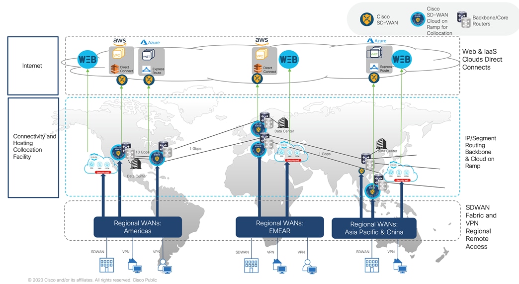
The following diagram outlines the high-level solution architecture.
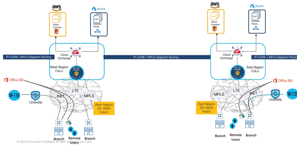
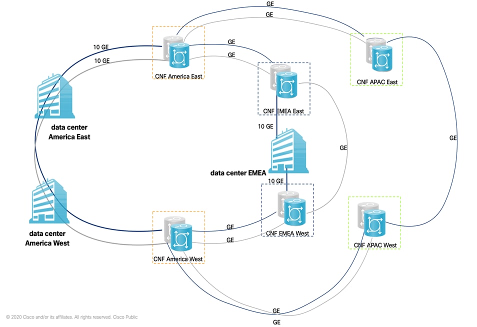
Managed backbone (or Core) interconnects regional data centers and global colocation facilities. It’s customer initial step in the transformation journey. Adopting collocation high bandwidth and low-cost global transport circuits offers target OPEx cost reduction objective, while choosing Cisco high end routing silicon and IOS-XR operating system provide highly available. and comprehensive routing and switching feature set solution.
A pair of Cisco Network Converged System (NCS) 5501 routers deployed at six globally distributed neutral carrier facilities (CNFs or Colocations). Enterprise procures inter-sites transport circuits, manages operation for core routers, and traffic engineering.
Managed backbone interconnections support IPv4 and IPv6-ready dual stack.
This solution considers the use of MPLS Segment Routing, as this technology provides complete control over the forwarding paths by combining simple network instructions. It does not require any additional protocols to bring scalability, fast convergence, failure protection, and a more natural way of traffic engineering. Segment Routing is used to steer traffic along any arbitrary path in the network. This allows operators to enforce low-latency and disjoint paths, regardless of the normal IGP forwarding paths. BGP is another key protocol to achieve a specific and controlled exchange of prefixes to deliver the services needed.
Segment routing is a method of forwarding packets on the network based on the source routing paradigm. The source chooses a path and encodes it in the packet header as an ordered list of segments. Segments are an identifier for any type of instruction. For example, topology segments identify the next hop toward a destination. Each segment is identified by the segment ID (SID), consisting of a flat unsigned 20-bit integer.
Segment Routing can be implemented by utilizing two different forwarding data planes: MPLS and IPv6. In the present design, MPLS SR an ordered list of segments is represented as a stack of the following labels:
● Segment Routing re-uses MPLS data plane without any change
● Segment represented as MPLS label
● Applicable to IPv4 and IPv6 address families
The segment routing domain includes the Core routers and the DC routers.
Each CNF has one anycast label representing its pair of routers, so the time of convergence is reduced when one of the routers fails.
The backbone solution implemented OSPFv2 for IPv4 and OSPFv3 for Ipv6 as Internal Gateway Protocol (IGP). OSFPv2, used to exchange IPv4 routes within the backbone only, and this protocol is going to distribute Segment Routing Segment IDs. OSPFv3 will be used for the IPv6 address family, but at this time, it doesn’t support Segment Routing. Customer’s NCS 5501s and data centers routers configured with OSPF backbone area (area 0) in OSPFv2 and v3 protocols. CoRC service group VNFs will not be part of the OSPF domain.
Border Gateway Protocol (BGP) is an Exterior Gateway Protocol (EGP) that allows the customer to create loop-free interdomain routing between Autonomous Systems (ASN). Routers in an autonomous system can use multiple Interior Gateway Protocols (IGPs) to exchange routing information inside the autonomous system and an EGP to route packets outside the autonomous system.
The customer decided to utilize single Private BGP Autonomous System Number (ASN) for BGP-enabled Backbone, data centers, and dynamically instantiated SD-WAN Cloud on Ramp for Collocation (CoRC) virtual services groups. A Public ASN replaces the Private one in the eBGP sessions between the CoRC virtual services and the Service Providers.
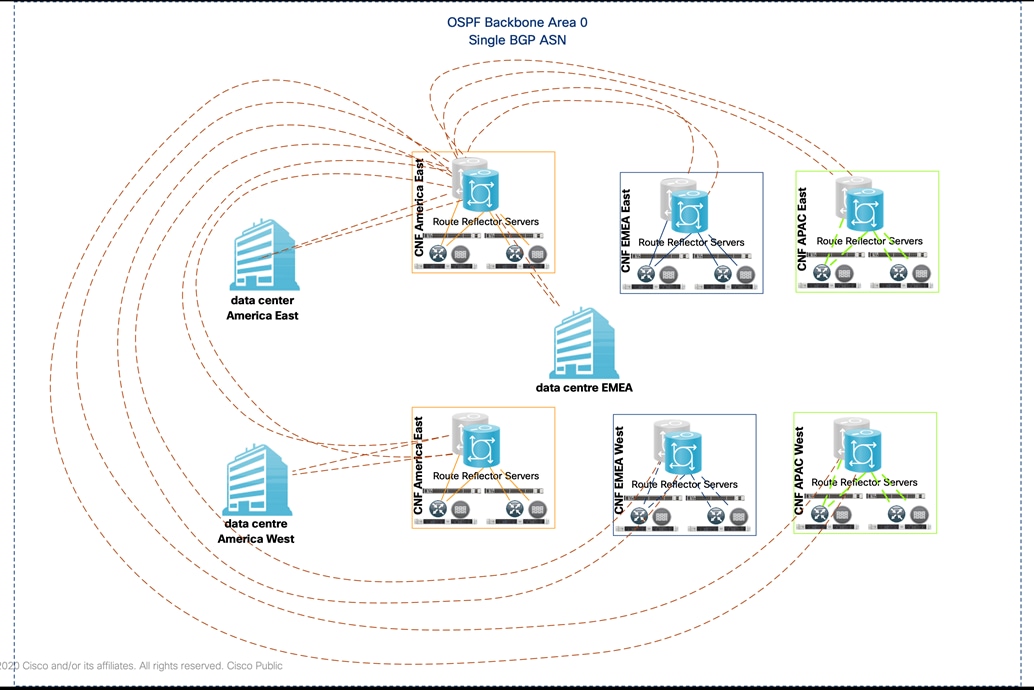
In order to avoid complex establishing full-mesh IBGP sessions between single ASN network devices, the America CNF hosted NCS 5501s pair routers deployed as highly available Internal BGP Route Reflector Server (RR). Other regions NCS 5001s, data centers routers and CoRC hosted virtual service groups that act as iBGP Route Reflector Clients (RRC). Please check details in the following section.
The following diagram has all the iBGP sessions in the Core where all the routers are route-reflector clients of CNF-East and CNF-West.
The following table outlines backbone design and implementation lessons learned.
Table 1. Enterprise Backbone - Lessons Learned
| Challenge |
Lesson Learned |
Recommendation |
| At the time of the design, the VNF does not support multicast packets, therefore VNFs doesn’t support OSPF sessions with the routers |
Contemplate the limitations of the VNFs. |
The iBGP sessions between routers and VNFs are established via the directly connected interfaces. |
| Anycast labels are not used while forwarding traffic from one VNF to another |
Consider the correct next-hop and the possible failure scenarios so the redundant path doesn’t blackhole the traffic. |
A route-policy was created to change the next-hop of the prefixes to the Loopback 1 (anycast segment), along with the command “ibgp policy out enforce-modifications”. |
| Delay measurement not supported because of the hardware |
Consider the hardware limitation when the platform is the smallest of the series family. |
It’s recommended to use ISIS over OSPF, because the former has more SR features developed in the released software versions. |
| Dynamic Tree SID (multicast) not supported because of the available Software version |
Consider that some of the newest features like Multicast, IPv6 SR, and PCEP depend on the newest platforms and versions. |
As there was no use case for the customer in the short term, Multicast was omitted. Until then, IOS-XR 7.3.1 version is the recommended release. |
| Multi-domain integration between SD-WAN and MPLS SR |
Single pine of glass management from Cisco vManage for SD-WAN fabric, as well as the backbone routers. |
Backbone routers managed via CLI. Multi-domain data plane and management plane integration is in the products roadmap. |
SD-WAN Cloud on Ramp for Colocation Architecture
The Cisco SD-WAN Cloud on Ramp for Colocation (CoRC) solution aggregates enterprise branch offices, campuses, remote users, business-to-business partners to key regional locations or colocations and provides intent-based deployment for secure multi-cloud connected services at the network edge for better quality of service, low traffic latency, simplified management, and increased security.
The CoRC solution provides this customer with multiple distributed branch offices that are clustered around major cities or spread over several countries the ability to regionalize the routing services in colocation facilities. These CNF facilities are physically closer to the branches and can host the cloud resources that the enterprise needs to access. So, essentially by distributing a virtual Cisco SD-WAN over a regional architecture of colocation facilities, the processing power is brought to the cloud edge.
Cisco Cloud on Ramp for Colocation enables IT to deploy network services faster, over an SD-WAN with simplified orchestration and management. With centralized orchestration, it is now simple and easy to design, provision and manage the trusted network services that are critical to businesses, while afford customer operation teams full-stack (hardware and software) management and control.
Cloud Connectivity: Connect Cloud/IaaS/SaaS apps to branch offices with operational ease. WAN aggregation at geographic/regional hub site(s) improves user experience due to proximity of hub site to clouds.
Internet Hand-Off: Apply consistent security policies and connect different types of users to the internet and between different service providers.
Secure Gateway: Maintain secure branch to internet connectivity and securely connect all my branches to the internet.
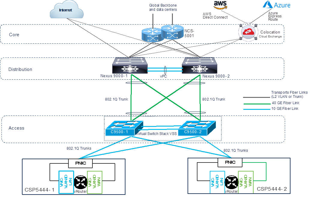
The following diagram outlines Cisco Cloud on Ramp for Collocation platform components.
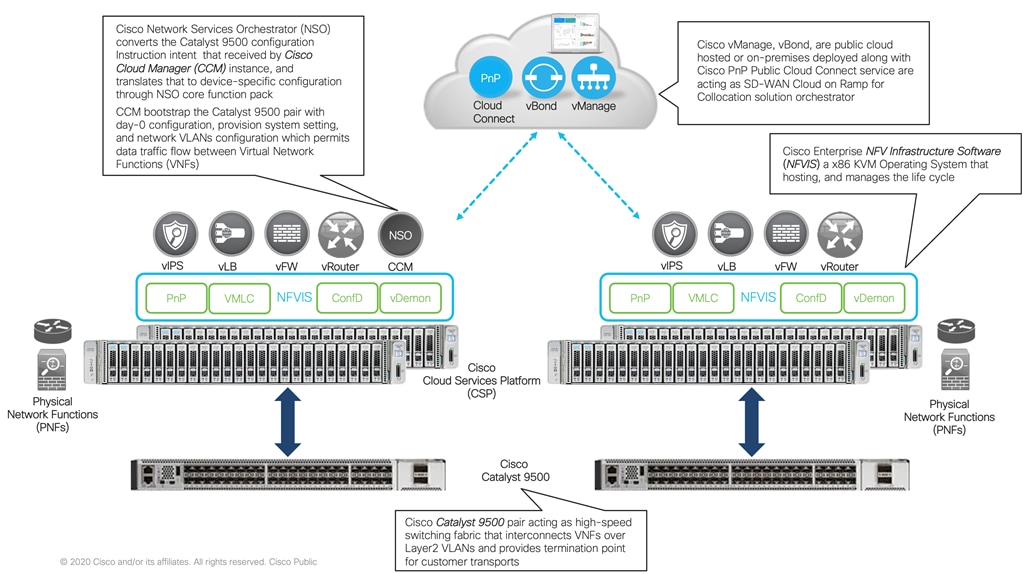
Cloud Services Platform (CSP) is an x86 Linux hardware platform that runs NFVIS software. It is used as the compute platform for hosting the virtual network functions in the Cisco SD-WAN CoRC for Colocation solution. The software for Cisco Network Function Virtualization Infrastructure Software (NFVIS) is used as the base virtualization infrastructure software running on the x86 compute platform. The Cisco SD-WAN Cloud on Ramp for Colocation solution supports both Cisco-developed and third-party Virtual Network Functions (VNFs).
The Network Fabric forwards traffic between the VNFs in a service chain by using a Layer2 and VLAN-based lookup. The Out of Band management switch configures the management network. The Out of Band management network connects the NFVIS software running on the CSP systems, the virtual network functions, and the switches in fabric. The vManage manages VNF management IP addresses and assigns through the VNF Day-0 configuration file. The Cisco SD-WAN Cloud on Ramp for Colocation solution manages the creation of virtual switch instances and the virtual NIC membership to create connectivity.
In Cisco SD-WAN Cloud on Ramp for Colocation solution deployment, the traffic between the VNFs is service chained externally through Cisco Catalyst 9500-40X or Cisco Catalyst 9500-48Y4C. The service chaining requirement provides service chaining functionality to the traffic across VNFs running either on a single CSP or across multiple CSP systems in a cluster. Cisco Colo Manager is hosted on NFVIS software in a docker container that manages the Cisco Catalyst 9500-40X switches.
A VNF can be connected to the physical network by using either Single Root IO Virtualization (SR-IOV) or through a software virtual switch. A VNF can have one or more virtual network interfaces (VNICs), which can be directly or indirectly connected to the physical network interfaces. A physical network interface can be connected to a software Open Virtual Switch (OVS) and one or more VNFs can share the virtual switch. The Cisco SD-WAN Cloud on Ramp for Colocation solution manages the creation of virtual switch instances and the virtual NIC membership to create connectivity. By default, all the physical interfaces and the management interface in the CSP system are available for use by VNFs.
In Cisco SD-WAN Cloud on Ramp for Colocation deployments, SR-IOV interfaces are configured in Virtual Ethernet Port Aggregator (VEPA) mode. In this mode, the NIC sends all the traffic that is received from the VNFs to the external Cisco Catalyst 9500-40X or Cisco Catalyst 9500-48Y4C switches. The Cisco Catalyst 9500-40X or Cisco Catalyst 9500-48Y4C transfers the traffic that is based on the L2 MAC address and VLAN. It can send the traffic back to the CSP or to an external connected network. The Catalyst 9500 switch ports that are connected to the CSP interfaces are configured in VEPA mode. When a VLAN is configured on a VNF VNIC, the VLAN must be configured on the connected port on Cisco Catalyst 9500-40X or Cisco Catalyst 9500-48Y4C switches.
A VNF using a SR-IOV interface and a VNF using the software switch can be service chained through the external switch fabric.
A single Cisco Colo Manager instance per cluster is brought up in one of the CSP devices after activating the cluster.
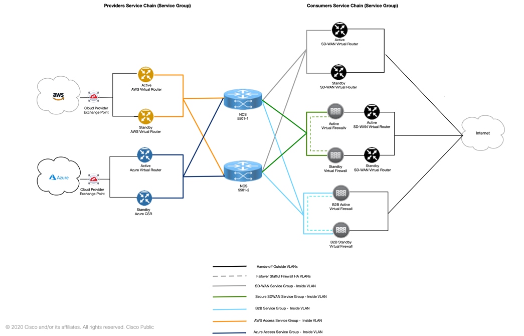
SD-WAN Cloud on Ramp for Colocation – Service Chain Design
Typically, Service Chain or Service Group separate consumers and providers across demarcations of trust or capacity for bandwidth demands.
Enterprise consumer (person or device) reaches to colocation Consumer service chain, which is configured with proper set of routing and security services.
Consumer service chain consists of an ordered pattern of connected routing and security VNFs or Physical Network Appliances (PNFs) that interconnect enterprise Branches/Campus corporate employees to various applications hosting clouds, such as data centers, and public clouds.
Consumer traffic once processed by the Consumer Service Chain gets routed to Provider Service Chain within regional colocation facility. Provider chain consists of ordered networking and security VNFs and PNFs pattern.
Cisco NCS-5001s Core router provides routing and forwarding function between the Consumer and Provider chains, and to external multi-clouds transports, as depicted in the following diagram.
Cisco vManage assists in designing, creating, and deploying VNFs; while maintaining high availability requirements for CSP/hypervisor placement. vManage used for developing and deploying Day0 configuration templates, maintains service chains life cycle; vManage also provides a global operational for all managed devices view.
Service chain design requires the following steps carried out between Cisco architects and customers networking /security engineering teams in order to define the following Key Performance Indicators (KPIs):
● Bandwidth requirement for ingress and egress traffic. The enabled features per VNF or PNF should be also considered
● VNF and PNF type and licensing
● Redundancy options (stateless or stateful)
● Control plane options
● Proactive traffic exchange mentoring
SD-WAN Cloud on Ramp for Colocation – Cluster Deployment
Customer deployed CoRC platform in six global Carrier Neutral Facilities (CNFs). CoRC cluster stack consists of Cisco x86 KVM compute servers (x2 CSP 5444) running Cisco NFVIS operating system software, and networking gear stack (2x C9500-40X-A). All components form a fabric that interconnecting brings up multiple virtual networking functions (VNFs) and multiple service chains on them. This stack connects customer consumers such as SD-WAN branch users, partners endpoints, business-to-business with various applications hosted providers, namely data centers, AWS, and Azure. Cisco vManage is used as the orchestrator to provision the devices in a colocation. Each colocation (CNF) is connected through the customer backbone network and does not have visibility of other colocations in the same site or across sites.
The following diagram depicts at a high-level on how the customer has deployed the CoRC solution in its six global CNF locations. Customer has deployed single CoRC cluster with two Cisco virtual routers in SD-WAN mode. These virtual routers will act as regional headend for the remote branches. Customer´s remote branches in one region will communicate with remote branches in other regions through regional headend. The details on the remote branch deployments will be provided in the SD-WAN section.
The first step in deploying CoRC solution is to bring up and activate the CoRC cluster. After CoRC cluster is activated, vManage establishes a DTLS tunnel with CSP devices in the cluster where it connects with the switches through Cisco Colo Manager. After the DTLS connection is established, a CSP device in the cluster is chosen to host the Cisco Colo Manager. Cisco Colo Manager is brought up and vManage sends global parameter configurations to the CSP devices and Cisco Catalyst 9500-40X switches.
The second step in deploying CoRC solution is to configure Service Groups. A service group consists of one or more service chains. A service chain is the structure of a network service and consists of a set of linked network functions. The service chain placement component chooses a CSP device that hosts each VNF in service chains. Customer deployed two Cisco virtual routers in SD-WAN mode with Day-0 configurations using the SD-WAN customized VNF package.
The final step in deploying CoRC solution is to attach the service groups to a cluster. While attaching a service group, vManage runs the Placement logic to determine which VNFs are placed on which CSP device. Depending on the Placement logic the first Cisco virtual router gets deployed on the first CSP while the second virtual router gets deployed on the second CSP. vManage pushes all switch-related service chain, cluster, and switch configuration to Cisco Colo Manager. Cisco Colo Manager translates all global and service chain configuration of Cisco Colo Manager into the device-specific configuration. Day-0 Cisco virtual router configurations will be sent to CSP devices. After all, virtual routers are downloaded, vManage sends the bulk configuration to spin all VNFs. CSP devices send notifications to vManage about VNF being brought up and its states. Once the Cisco virtual router are successfully brought up, a device template with Day-N configurations can be created on vManage. A device template with Day-N configuration can be attached to Cisco virtual router.
The following table outlines SD-WAN Cloud on Ramp for Colocation design and implementation lessons learned.
Table 2. SD-WAN Cloud on Ramp for Colocation – Lessons Learned
| Challenge |
Lesson Learned |
Recommendation |
| VNF packages design |
The CoRC solution supports both Cisco and third party VNF package. It is flexibility to create and customize any VNF package. VNF packages are not posted on CCO. |
Create “Custom VNF package” that based on the customer service-group design requirements. |
| SD-WAN VNF redeployment using the same devices serial number |
Enterprise Network Admin can re-deploy SD-WAN VNF and keep the existing WAN edge device serial numbers. |
Follow the following workflow steps: 1. Decommission SD-WAN VNF from vManage to reset token 2. Detach service group from Cloud OnRamp cluster 3. Make required changes to service chain 4. Re-attach service group to Cloud OnRamp cluster to deploy SD-WAN VNF 5. Re-attach vManage device template to SD-WAN VNF |
| Service Chain monitoring |
Cisco SD-WAN CoRC supports Service Chain monitoring, and the feature can be enabled per service chain with user defined input and output monitoring IP address. |
The monitor uses nping to check the reachability between input and output monitoring IPs. By default, the monitor runs every 30 minutes as defined in vManage -> Administration -> Settings -> Statistics Configuration. The impact to CPU or network is minimum, and when the probe fails, system event can be generated, and user can be notified via SNMP, logging or email. |
Customer has deployed two Cisco SD-WAN fabrics, Global and China, connected via global IP backbone.
Customer selected Cisco Software-Defined WAN (SD-WAN) fabric to take advantage of inexpensive global broadband Internet services and to route intelligently a trusted SaaS cloud-bound traffic directly from remote branches.
Global SD-WAN fabric is deployed using cloud hosted controllers at Cisco hosting services, while China SD-WAN fabric uses on-prem controllers. Global SD-WAN spans over AMER, EMEA, and APAC covering over 700 business critical branch sites and China will cover 20+ sites. Figure below shows a high-level view of the SD-WAN fabric layout.
Each global region will have a pair of Cisco virtual routers in SD-WAN mode acting as head-end routers hosted at regional colocation facility. Virtual router pair serve as a hub transit for intra and inter region traffic between the sites. In each region, sites are divided into East and West, and they will prefer their East and West head-ends for communication while having a redundant headend in case the primary fails.
SD-WAN Fabric – Branch Edge Architecture
Branch sites are divided into two categories: Standard and Premier.
Standard sites will use Cisco’s Integrated Services Routers 1000 series (ISR1k) with LTE backup. These sites will have Hub and Spoke topology to limit the number of tunnels and routes.
Premier Sites will use Cisco’s Integrated Services Routers 4000 series (ISR4k) with redundant Internet connections. These sites will have full mesh tunnels within the region.
We also deployed auto-tunnel feature in order to interconnect SD-WAN branch edges with Umbrella SIG over the Internet. This alleviates any manual tunnel configuration and chooses Umbrella data centers with automated failover built in.
SD-WAN Fabric – Policy Architecture
Customer is using SD-WAN policies to leverage its full capabilities. Control policies are used to create hub-spoke and full mesh topologies with proper route tagging for filtering and path preferences. Routing interaction between SD-WAN OMP with branch OSPF and IP Core BGP is also controlled using SD-WAN policies.
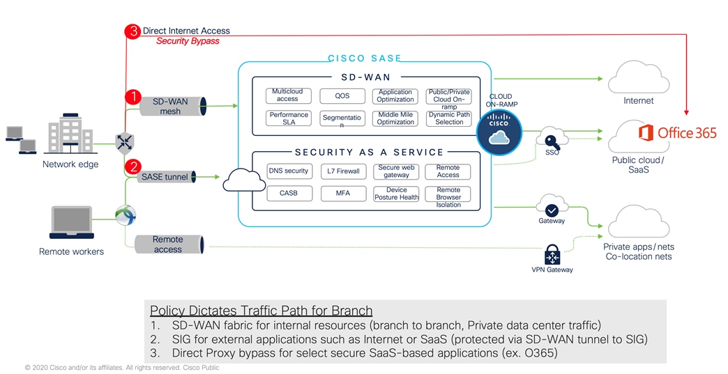
Data policies are used to provide more granular control on path selection for specific user data. For example, traffic destined to the known anycast address of Cisco AnyConnect destination or traffic to trusted applications like O365 will locally breakout at each branch instead of riding the SD-WAN fabric or Umbrella SIG tunnel. Similar policy is used to send traffic to the Umbrella SIG tunnel for securing Internet bound traffic. The following picture describes a sample branch leveraging SD-WAN fabric for internal data communication, Umbrella SIG for securing Internet bound traffic, and local breakout for direct connections to known/trusted applications like O365.
The following table outlines SD-WAN Fabric design and implementation lessons learned.
Table 3. SD-WAN Fabric - Lessons Learned
| Challenge |
Lesson Learned |
Recommendation |
| List of Critical Applications and their networking requirements |
Some of the customer applications are not resilient to network traffic fragmentation. |
Applications enhancement is required in order to add resiliency layer to network traffic fragmentation. |
| Service Provider transport circuits validation for performance contracted SLA (packet per second, delay, and jitter) |
Contractual SLA between enterprise customer and service provider should be validated prior to migrate a site from legacy WAN (MPLS) to Internet. |
Proper validation planning should be planned by the enterprise networking team. End-to-end traffic performance testing achieved by using certified tools such as Cisco ThousandEyes. |
Cisco Umbrella - Cloud Security Architecture
Cisco Umbrella provides the cloud security pillar of the SASE (Secure Access Service Edge) architecture for enterprise customers.
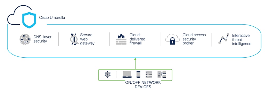
Cisco Umbrella is a cloud-delivered security service (SaaS) that brings together essential functions that you can adopt incrementally, at your pace. Umbrella unifies secure web gateway, DNS security, Cloud-Delivered Firewall (CDFW), cloud access security broker functionality, and threat intelligence. Deep inspection and control ensure compliance with acceptable-use web policies and protects against internet threats.
Accelerated threat detection/response and centralized management makes it ideal for decentralized networks.
By enabling all of these security functions from a single cloud-delivered service and dashboard, Umbrella significantly reduces the time, money, and resources previously required for deployment, configuration, and integration tasks.
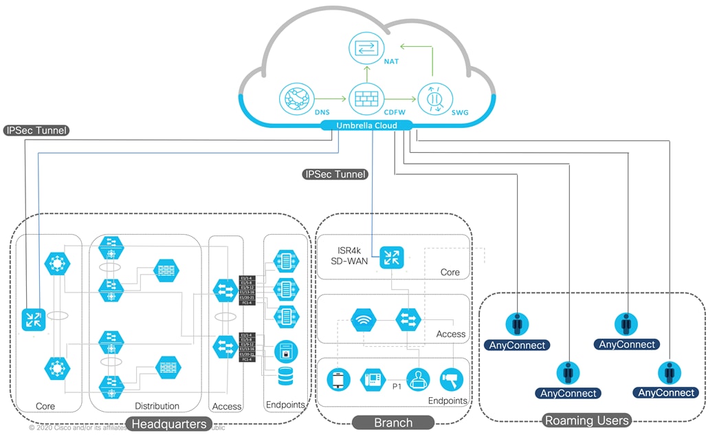
If all of the capabilities of Umbrella are enabled, here’s an example of how the flow will work:
● Umbrella DNS is resolved first. It is the first check for malicious or unwanted domains and is based on the defined DNS policies. This reduces the quantity of traffic that is sent to the CDFW and SWG, improving responsiveness and performance
● All traffic that has made it through DNS checks will be inspected by the CDFW. The firewall provides visibility and control for outbound internet traffic across all ports and protocols (Layer3/Layer4) as well as Layer7
● The SWG will inspect any traffic that is destined for ports 80/443 after it has been permitted by the CDFW to provide a deeper security inspection. It will also apply visibility, application and control policies
This unified Umbrella service allows the customer to secure their Internet-bound traffic in the following ways:
● On-Premises Traffic
◦ Web Traffic: all on-prem users/machines web traffic (ports TCP/80 for HTTP, and TCP/443 for HTTPS) will be forwarded to the Umbrella SWG (Secure Web Gateway) to be inspected, controlled and filtered by the Umbrella cloud proxy (via SIG IPsec tunnel)
◦ Non-Web Traffic: all on-prem users/machines non-web traffic will be forwarded to the Umbrella CDFW to be filtered by the Umbrella Layer3/Layer4 cloud firewall (via SIG IPsec tunnel)
◦ DNS traffic: all on-prem users/machines DNS traffic (port UDP/53) will be forwarded to the Umbrella DNS (Domain Name System) to be controlled and filtered by the Umbrella cloud DNS (via Virtual Appliance servers)
● Off-Premises Traffic
◦ Web Traffic: all off-prem users web traffic (ports TCP/80 for HTTP, and TCP/443 for https) will be forwarded to the Umbrella SWG to be inspected, controlled and filtered by the Umbrella cloud proxy (via AnyConnect client)
◦ DNS traffic: all off-prem users DNS traffic (port UDP/53) will be forwarded to the Umbrella DNS (Domain Name System) to be controlled and filtered by the Umbrella cloud DNS (via AnyConnect client)
All HTTPS web traffic will be decrypted (SSL/TLS decryption) for full URL and content inspection by the cloud proxy engines, which include anti-malware/anti-virus (AV), advanced malware protection (AMP), and file sandboxing (Threat Grid). Decryption can be applied selectively by content and destination, such as allow/block lists, domains/URLs, and applications.
Advanced capabilities such as inline DLP and Remote Browser Isolation (RBI) can also be applied through Umbrella’s integrated policies, with full visibility in Umbrella’s reporting.
A customer defined AUP (acceptable use policy) will enforce customer’s security and category policy on web and DNS traffic, based on AD user/group identities among other criteria.
The Internet traffic redirection model at each of the customer’s sites globally is DIA (Direct Internet Access). Meaning that through integration with Cisco Viptela SD-WAN solution, an IPsec VPN tunnel is established from each site’s edge router to the closest Umbrella data center.
With this solution in place, users will have a uniform experience regardless of their location (on- or off-prem) and will be protected from Internet threats at all times. Backing all this is threat intelligence from Cisco Talos, one of the largest commercial threat intelligence teams in the world.
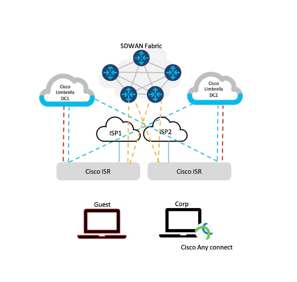
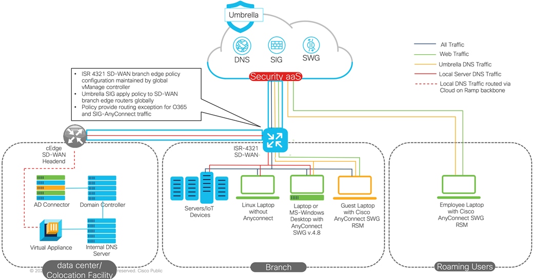
The following diagram is showing a typical SD-WAN/Umbrella deployment: Local Site (branch), roaming guest devices, and the Cisco SD-WAN branch edge router (e.g., ISR 4321). On-premises traffic flows to Umbrella cloud via the SIG IPSec tunnel, off-premise traffic flows to Umbrella cloud via AnyConnect agent. Various site edge devices are connected together via SD-WAN TLS tunnels for local/internal traffic. DNS traffic from the data center is sent to the Umbrella cloud via the Virtual Appliance. Next project phase should address migrating remote roaming devices to Umbrella.
The following table outlines SD-WAN Fabric design and implementation lessons learned.
Table 4. Cisco Umbrella - Lessons Learned
| Challenge |
Lesson Learned |
Recommendation |
| Customer is using Public (non-RFC1918) IP space for internal network addressing
|
Public IP source addresses are not permitted through SIG IPSec tunnel. Cisco CX worked with customer to identify if there are hosts on the network/at sites utilizing public IP addresses prior to a site going live. |
Cisco CX worked with Cisco Umbrella operations team to add exceptions and provision customer specified public IP addresses be routable via the SIG tunnel, and ensure those addresses are not leaked/advertised by the customer to public Internet hence cause routing a loop. |
| Active Directory Connector (AD-C) scalability in multi-AD domain scenarios |
For multi-AD domain with Virtual Appliance, 1 AD-C per domain is required, plus a recommended backup AD-C for redundancy. Depending on number of sites and domains this number can ramp drastically. |
Work with the customer to consolidate multiple AD domains into a single domain to avoid domain integration and connector scaling issues. Alternatively, in a near-future version of AD-C, this issue is resolved by use of a multi-domain Windows Event Log Collector. |
| Some traffic will not work properly if sent through the SIG tunnel for various reasons, for example customer egress IP required, SaaS traffic which should not be proxied (e.g., Office 365) |
Cisco CX worked with customer to plan, design, and implement a “local breakout” strategy for that traffic, and exclude it from the tunnel. |
After the desired applications/domains are identified, they can be added to a routing policy on vManage, so they will not be routed through SIG tunnel and break out locally instead. |
| Challenges with SAML authentication and HTTPS decryption |
Cisco CX worked on multiple options to find a solution to overcome these challenges, such that HTTPS decryption will still occur for majority of devices, while it will not interfere with traffic which is not decryption friendly. |
Cisco CX recommended a hybrid approach, where majority of traffic was being authenticated and redirected by AnyConnect agent, while rest of traffic could be authenticated via SAML and decrypted where necessary. |
Cisco Customer Experience Services Differentiators
Deploying multi-cloud platforms while maintaining cohesive security for global distributed SD-WAN sites comes with a list of potential high-risk on enterprise business reputation.
Cisco CX teams armed with product knowledge, and best industry practices will partner with the customer to ensure quick solutions adoption and assist achieving business goals.
Cisco was able to successfully address the customer’s key business and technology tenets of improving user experience, reducing cost, and minimizing risk with this transformation.
User experience was improved by bringing services closer to the user leveraging regionalized colocation facilities. This allows for direct peering relationships to Internet/SaaS/public cloud providers, reducing latency, and ultimately improving the user experience.
Cost was reduced by improving both CapEx and OpEx. Considering this architecture regionalizes Internet, SaaS, and public cloud connections, we can leverage colocation cross-connects and reduce the amount of transport costs (CapEx improvement). To improve OpEx, we leveraged automation tactics. According to McKinsey, 80% of configuration is performed manually, which is not only erroneous, but also time consuming. The solution leverages automation via centralized configuration using templates. These pre-configured templates instantiate the configurations, including dynamic routing policies to peel off certain SaaS-based applications and send those as Direct Internet Access (DIA). These templates help bring consistency to the deployments, and ultimately improve OpEx.
We minimized risk by leveraging the integration and automation of the SASE building blocks of Cisco’s SD-WAN and Cisco’s Secure Internet Gateway (SIG). Considering the SD-WAN and SIG both leverage Smart Licensing and can identify entitlements, the integration allows for the SD-WAN solution to obtain the requisite keys (credentials) needed to communicate with SIG. Once the communication is securely established, the template-based configurations mentioned above can be used to auto-launch VPNs to SIG and instantiate the appropriate policies per user/site. That type of automation and integration between the SASE solution building blocks limits the amount of manual intervention required, hence reducing errors and potential vulnerabilities, ultimately minimizing risk.
This paper is a first in a series of SASE architecture documents detailing the services approach utilized to design, implement, and deploy global scale SASE solution consisting of SD-WAN fabric with Cloud on Ramp for the workplace, AnyConnect for remote access, all integrated with Cloud Security (Umbrella).
In “Part Two”, we intend to provide customer gradual progress on full Cisco SASE stack adoption.
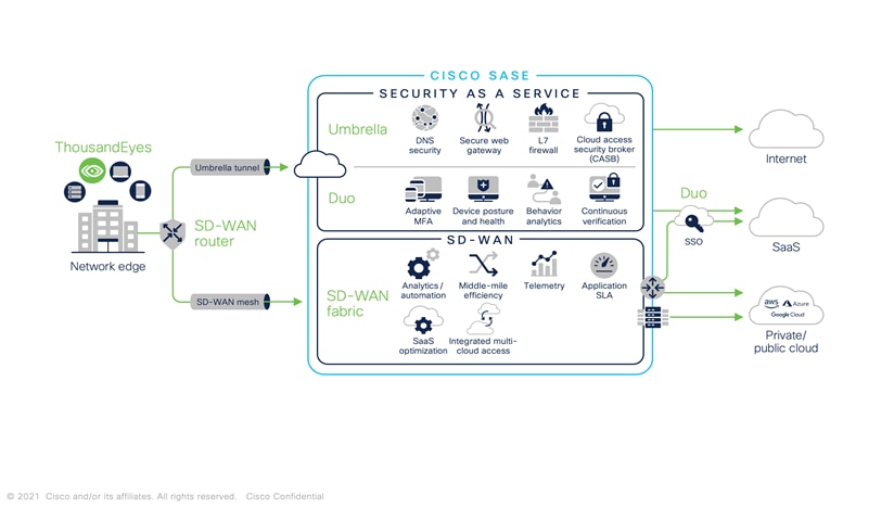
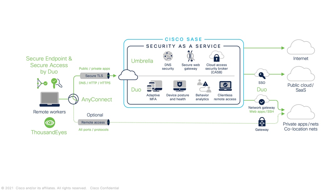
We will “zoom-in” into the various layers and components of the Cisco SASE architecture, while providing the “Services” and “Product” Intersection for delivering the highest quality and efficacy cybersecurity solution. The following diagrams outline Cisco SASE stack for network edge and roaming users.
Ehab Hadi, Principal Architect, Technical Transformation Group (TTG), CX Field Services
Anthony Sabella, Principal Sales Architect, Global Enterprise Segment, Cisco
Azharuddin Mohammed, Customer Delivery Architect, Technical Transformation Group (TTG), CX Field Services
Julieta Mauleon Fernandez, Consulting Engineer, CX Centers Americas
Travis Oke, Security Consulting Engineer, Technical Transformation Group (TTG), CX Field Services
Vahid Afrakhteh, Security Consulting Engineer, Technical Transformation Group (TTG), CX Field Services
Zaheer Aziz, Customer Delivery Architect, Technical Transformation Group (TTG), CX Field Services
Hazim Dahir, Distinguished Engineer, CX CTO
Yenu Gobena, Distinguished Engineer, CX CTO
Vijay Raghavendran, Distinguished Engineer, CX CTO
Balaji Sundararajan, Principal Engineer, Enterprise Networking & Cloud, Cisco
Meghan Diaz, Director Product Marketing – Umbrella
Nathan John Sowatski, Principal Engineer, CX CTO
Steve Brunetto, Product Manager – Umbrella
Jonny Nobel, Leader Technical Marketing – Umbrella
Prashant Tripathi, Chief Architect-CTO SD-WAN
Satinder Khasriya, Product Marketing Manager
Madhu Somu, Senior Product Manager