Cisco ACI Multi-tier Architecture White Paper
Available Languages
Bias-Free Language
The documentation set for this product strives to use bias-free language. For the purposes of this documentation set, bias-free is defined as language that does not imply discrimination based on age, disability, gender, racial identity, ethnic identity, sexual orientation, socioeconomic status, and intersectionality. Exceptions may be present in the documentation due to language that is hardcoded in the user interfaces of the product software, language used based on RFP documentation, or language that is used by a referenced third-party product. Learn more about how Cisco is using Inclusive Language.
Cisco ACI Multi-tier design considerations
Multi-tier Cisco ACI fabric configuration
Tier-2 leaf switch registration
This document describes the details of Cisco® Application Centric Infrastructure (Cisco ACI™) Multi-tier architecture, which is introduced in Cisco Application Policy Infrastructure Controller (APIC) Release 4.1. Cisco ACI Multi-tier provides the capability for vertical expansion of the Cisco ACI policy domain and its associated benefits.
Until a few years ago, in traditional data centers a 3-tier architecture of core-aggregation-access switching had been a common design model for many enterprise networks. The primary reason for this architecture was to provide a fabric for high-speed packet switching between multiple aggregation modules connecting to the data center core.
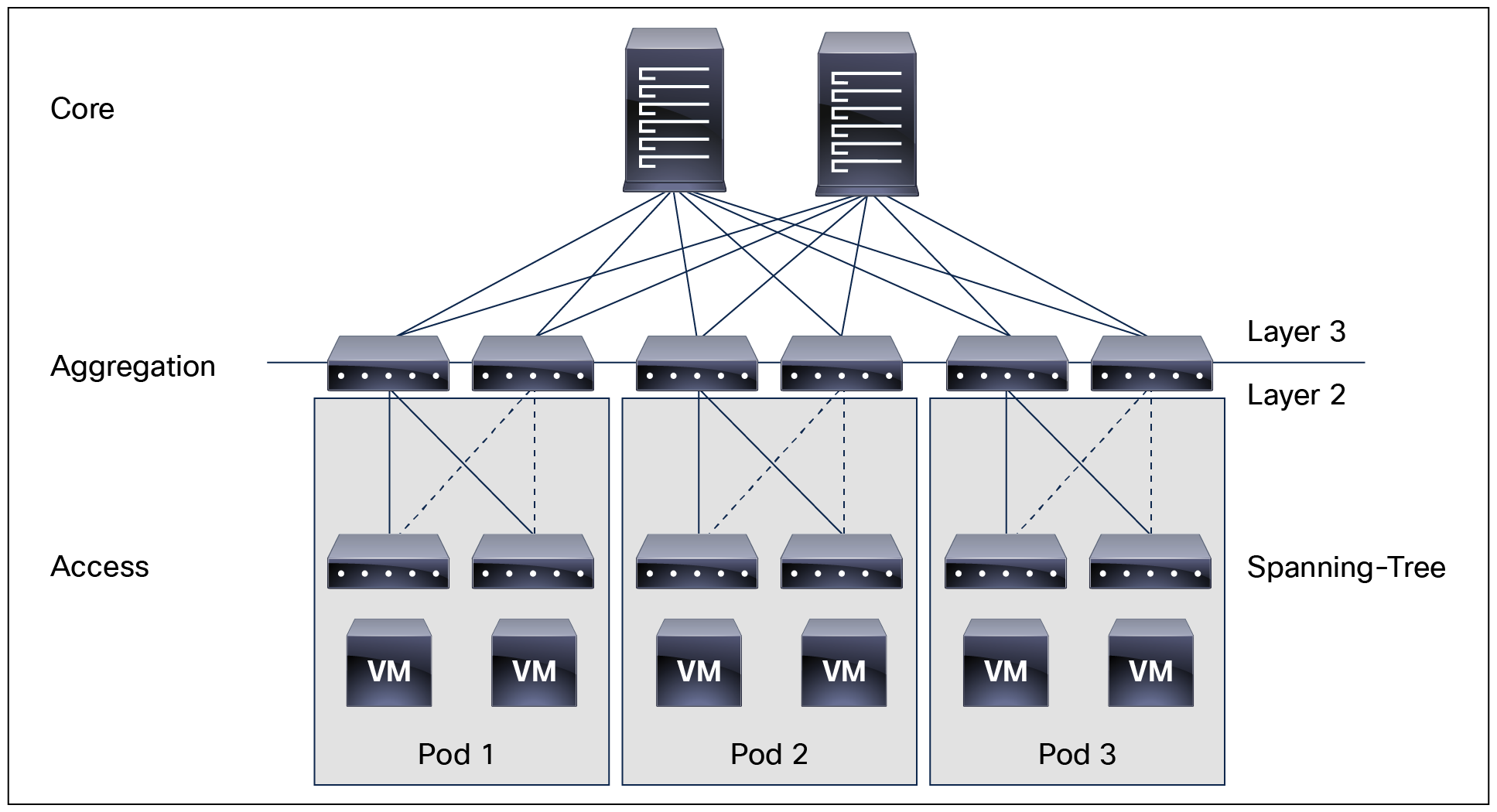
Traditional 3-tier architecture (core, aggregation, and access) topology
But the traditional model had its limitations when the virtualization of computing brought a distributed workload environment with an increase in east-west traffic. The complexities of Layer 2 networks running Spanning Tree protocol and a lack of efficient forwarding for server-to-server traffic required a new design model.
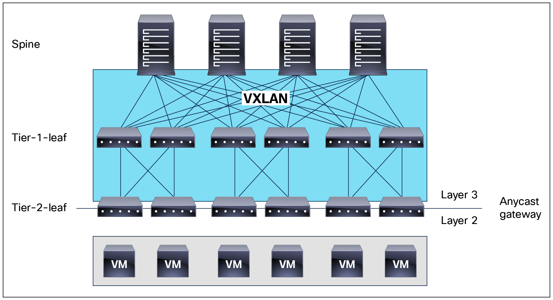
To overcome the limitation of a traditional network, Cisco started working on Clos network–based 2-tier spine-and-leaf architecture and developed the VXLAN-based overlay system, which allowed for efficient handling of traffic between any two endpoints in the fabric and consistent latency for workloads. Cisco also pioneered the policy-based automation with its Application Centric Infrastructure (ACI).

Cisco ACI 2-tier architecture (spine and leaf) topology
The traditional model of Multi-tier is still required today. The primary reason for this is cable reach, where many hosts are located across floors or across buildings; however, due to the high pricing of fiber cables and the limitations of cable distances, it is not ideal in some situations to build a full-mesh two tier Clos fabric. In those cases, it is more efficient for customers to build a spine-leaf-leaf topology and continue to benefit from the automation and visibility of Cisco ACI.
Starting with the Cisco APIC Release 4.1(1), you can now create a Multi-tier Cisco ACI fabric topology that corresponds to the core-aggregation-access architecture. The new design for Cisco ACI incorporates the addition of a tier-2 leaf layer for connectivity to hosts or servers on the downlink ports and connectivity to the leaf layer (aggregation) on the uplink ports.
Cisco ACI Multi-tier architecture (spine, tier-1 leaf, and tier-2 leaf) topology
Cisco ACI Multi-tier design considerations
Only Cisco Cloudscale switches are supported for Multi-tier spine and leaf.
● Spine: EX/FX/C/GX/GX2 spines (For example, Cisco Nexus 9332C, 9316D-GX, 9348D-GX2A, 9408 and 9500 with EX/FX/GX linecards)
● Tier-1 leaf: EX/FX/FX2/FX3/GX/GX2 except Cisco Nexus 93180LC-EX
● Tier-2 leaf: EX/FX/FX2/FX3/GX/GX2
For details on supported hardware, see https://www.cisco.com/c/en/us/td/docs/dcn/aci/apic/6x/getting-started/cisco-apic-getting-started-guide-62x/fabric-initialization-and-switch-discovery/multi-tier-fabric-topologies-example.html.
In a multi-tier topology, all switch to switch links must be configured as fabric ports. You can also use ports that by default are downlink ports by configuring them to be fabric ports. Special care must be taken when choosing which port from tier-2 leaf switches is connected to tier-1 leaf switches. This is because the downlink to fabric link port conversion can be done only after a leaf is discovered by APIC. If the APIC is connected to a tier-2 leaf, at least one tier-2 leaf default fabric port must be connected to a default fabric port on a tier-1 leaf. By ensuring this, APIC can discover both the tier-2 leaf that is attached to APIC and the tier-1 leaf that the tier-2 leaf is attached to. After this initial discovery you can convert additional ports on the tier-1 and tier-2 leaf switches to be fabric ports. Also, each Tier-1 leaf should have at least one default fabric port connected to a tier-2 leaf port.
In summary these are the connectivity requirements for tier-2 leaf switches:
● If APIC is connected to a tier-2 leaf: one default fabric port of the Tier-2 leaf must be connected to a default fabric port of a tier-1 leaf.
● If no APIC is connected to a tier-2 leaf: one default fabric port of the Tier-2 leaf must be connected to any port of a tier-1 leaf.
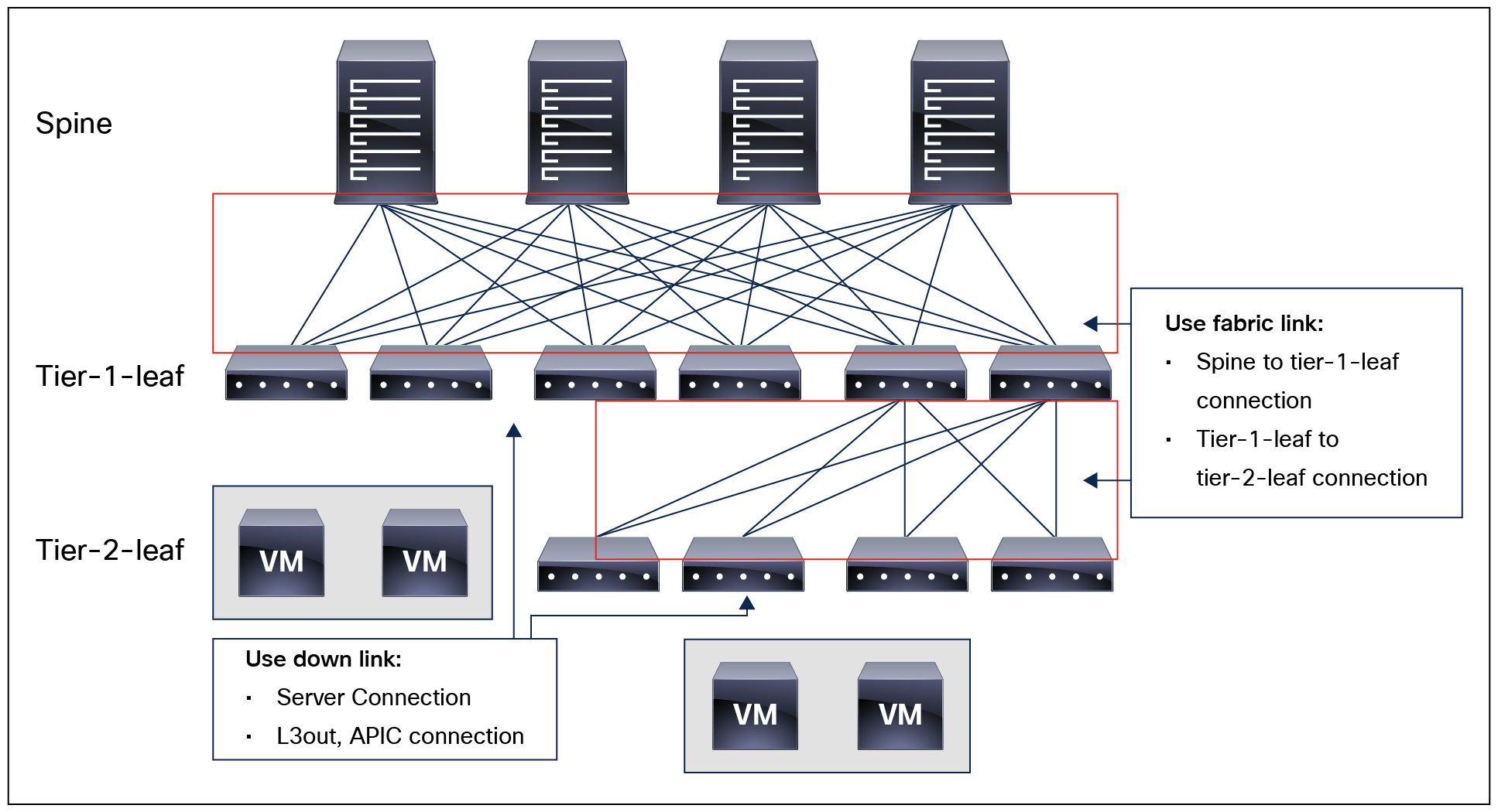
Cisco ACI multi-tier architecture (spine, tier-1 leaf, and tier-2 leaf) topology
Design considerations for Cisco ACI Multi-tier architecture include the following:
● Multi-tier architecture is supported only with APIC release 4.1 and later.
● Supported topology is spine – tier-1 leaf – tier-2 leaf.
● Tier-2 leaf switch fabric ports are connected to tier-1 leaf switch fabric ports.
● Tier-2 leaf can connect to more than two tier-1 leaf switches, in comparison to a traditional double-sided vPC design, which has only two upstream switches. The maximum number of ECMP links supported by tier-2 leaf to tier-1 leaf is 18.
● There are no restrictions of EPG, ESG, L3Out, APIC or FEX connectivity to tier-2 leaf switches. They can be connected to tier-1 leaf switches or to tier-2 leaf switches. Per leaf scale is independent regardless of Tier-1 or Tier-2.
● Tier-1 leaf switches can have both hosts and tier-2 leaf switches connected on it.
● Multi-tier architecture supports Multi-Pod and Multi-Site.
● Tier-2 leaf switches cannot be connected to remote leaf switches (tier-1 leaf switches).
● Recommendation for tier-2 leaf: Use at least one of the default uplinks as a fabric link to ensure recovery in case of factory reset.
● To convert downlink ports to fabric ports or fabric ports to downlink ports, reloading the switch is required. Please see the link for more information. https://www.cisco.com/c/en/us/td/docs/dcn/aci/apic/6x/l2-configuration/cisco-apic-layer-2-networking-configuration-guide-62x/access-interfaces-62x.html.
● Scale: The maximum number of tier-1 leaf switches and tier-2 leaf switches combined is equal to the maximum number of leaf switches in the fabric (200 per pod; 500 per fabric with multiple pods).
● A tier-1 leaf that is connected to a tier-2 leaf must follow the support matrix (see https://www.cisco.com/c/en/us/td/docs/dcn/aci/apic/6x/getting-started/cisco-apic-getting-started-guide-62x/fabric-initialization-and-switch-discovery/multi-tier-fabric-topologies-example.html), but first generation leaf switches (non-EX/FX) can coexist in the same fabric, as long as tier-2 leaf switches are not connected to these.
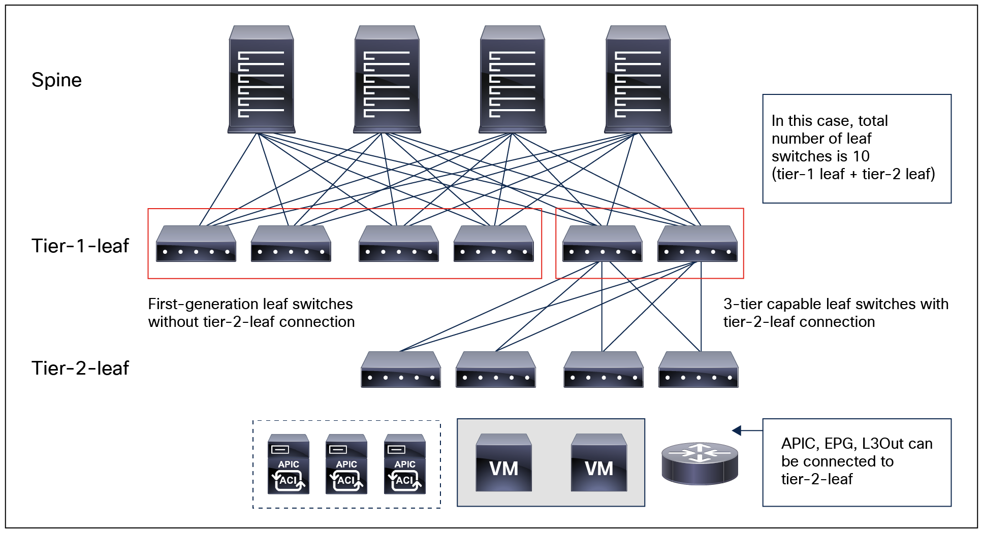
Cisco ACI multi-tier architecture (spine, tier-1 leaf, and tier-2 leaf) topology consideration
Multi-tier Cisco ACI fabric configuration
There is no additional configuration required on spine switches for a Multi-tier Cisco ACI fabric. If the tier-1 or tier-2 interfaces that are for switch to switch connectivities need to be converted to fabric ports, the configuration to do so is highlighted in the following guide: https://www.cisco.com/c/en/us/td/docs/dcn/aci/apic/6x/l2-configuration/cisco-apic-layer-2-networking-configuration-guide-62x/access-interfaces-62x.html.
Tier-2 leaf switch registration
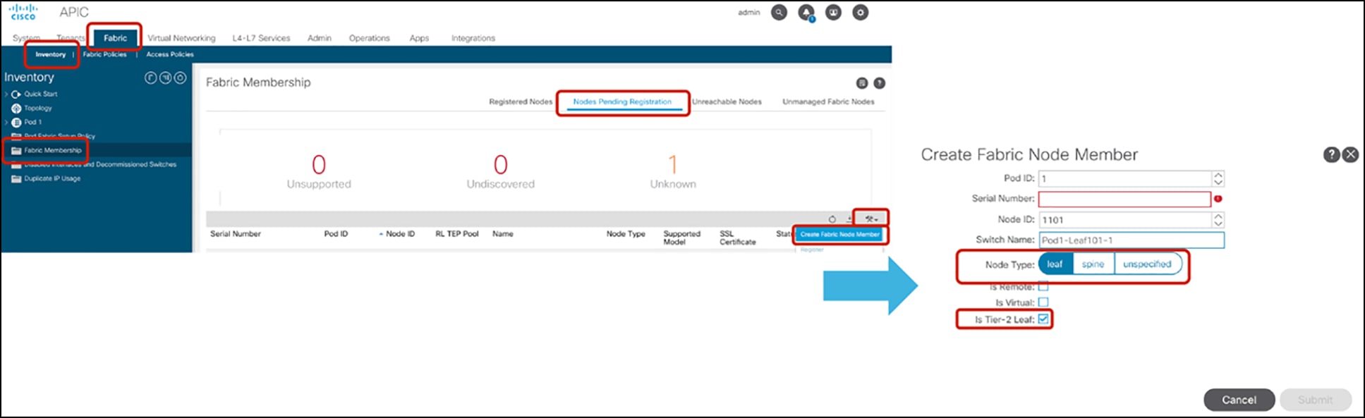
Tier-2 leaf configuration can be done as part of switch registration. If the node is already running as a tier-1 leaf, we need to perform “Remove from controller” first, then register it as a tier-2 leaf.
The location is Fabric > Inventory > Fabric Membership > Nodes Pending Registration > Create Fabric Node Member. You need to check “Is Tier-2 Leaf” option (Figure 6).
Tier-2 leaf switch registration
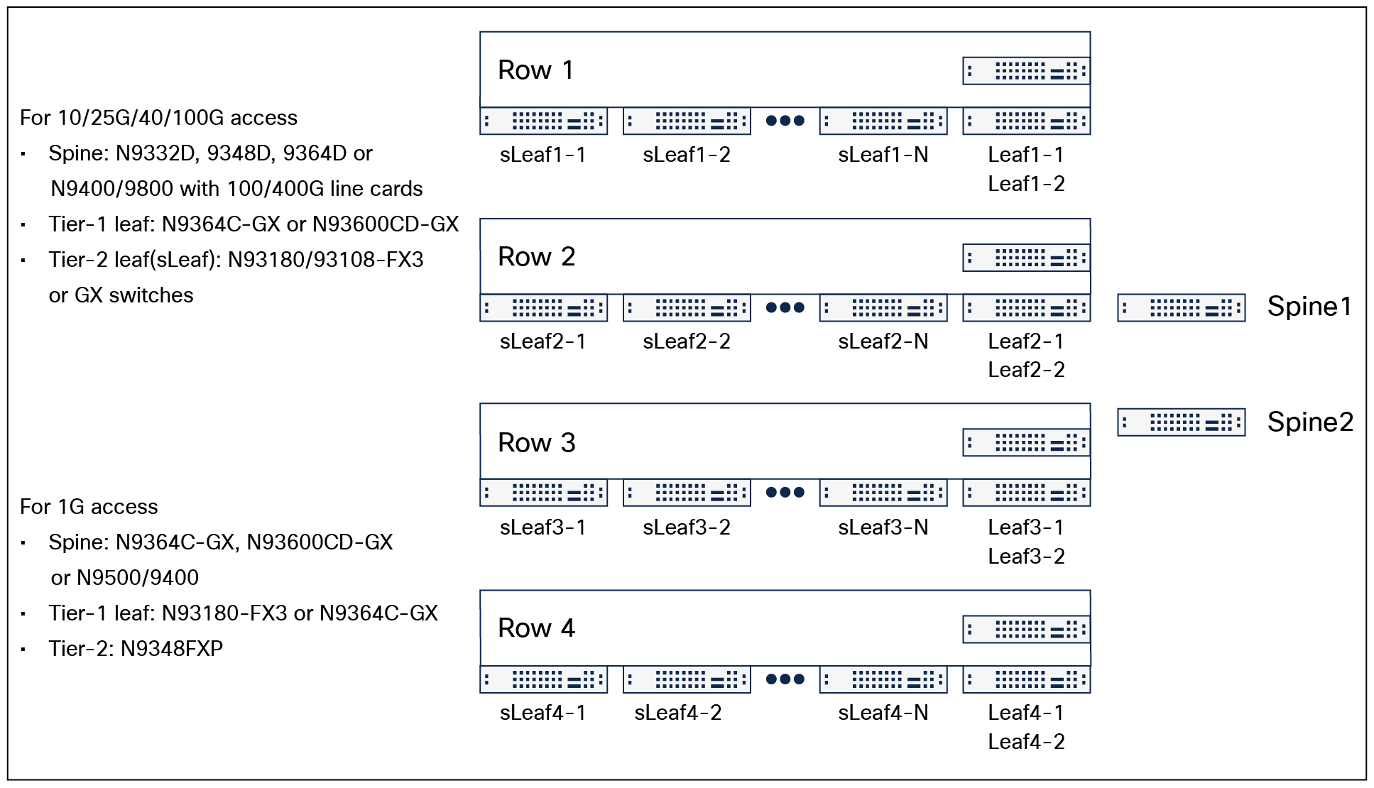
This section explains topology examples. Note that because several designs and requirements are possible, the example used in this document may not exactly reflect your environment.
The bullet list below describes the topology requirements:
● Multiple server racks in different rows in a floor or data center
● 100/400G fabric link for spine and tier-1 leaf link
● 40/100G fabric link for tier-1 leaf and tier-2 leaf link
● 10/25/40/100G server link
● Avoid full-mesh cablings across rows
The potential spine and leaf switch models in the topology requirements are as follows:
● Spine: Cisco Nexus 9332D-GX2B, Cisco Nexus 9348D-GX2A, Cisco Nexus 9364D-GX2A or Cisco Nexus 9500/9400 with line cards for 100/400G fabric links.
● Tier-1 leaf: Cisco Nexus 9364C-GX (40/100G fabric links) or 93600CD-GX (40/100/400G fabric links) as End of Row (EoR) switch.
● Tier-2 leaf: Cisco Nexus 93180/93108 FX3 or GX switches as Top of Rack (ToR) switch.
Topology example
If there is 1G server access, and there is no high bandwidth requirement, using Cisco Nexus 93180FX3 or Nexus 9364C-GX as tier-1 leaf and Cisco Nexus 9348FXP as tier-2 leaf is also a good option. 10G connectivity can be used as fabric ports if the port is a fabric link.
● Cisco Application Centric Infrastructure (Cisco ACI)
● Cisco Application Policy Infrastructure Controller (APIC)
● Cisco ACI Multi-Pod White Paper
● Cisco AI Multi-Site Architecture White Paper