FlashStack for Hybrid Multicloud GitOps White Paper
Available Languages
Bias-Free Language
The documentation set for this product strives to use bias-free language. For the purposes of this documentation set, bias-free is defined as language that does not imply discrimination based on age, disability, gender, racial identity, ethnic identity, sexual orientation, socioeconomic status, and intersectionality. Exceptions may be present in the documentation due to language that is hardcoded in the user interfaces of the product software, language used based on RFP documentation, or language that is used by a referenced third-party product. Learn more about how Cisco is using Inclusive Language.
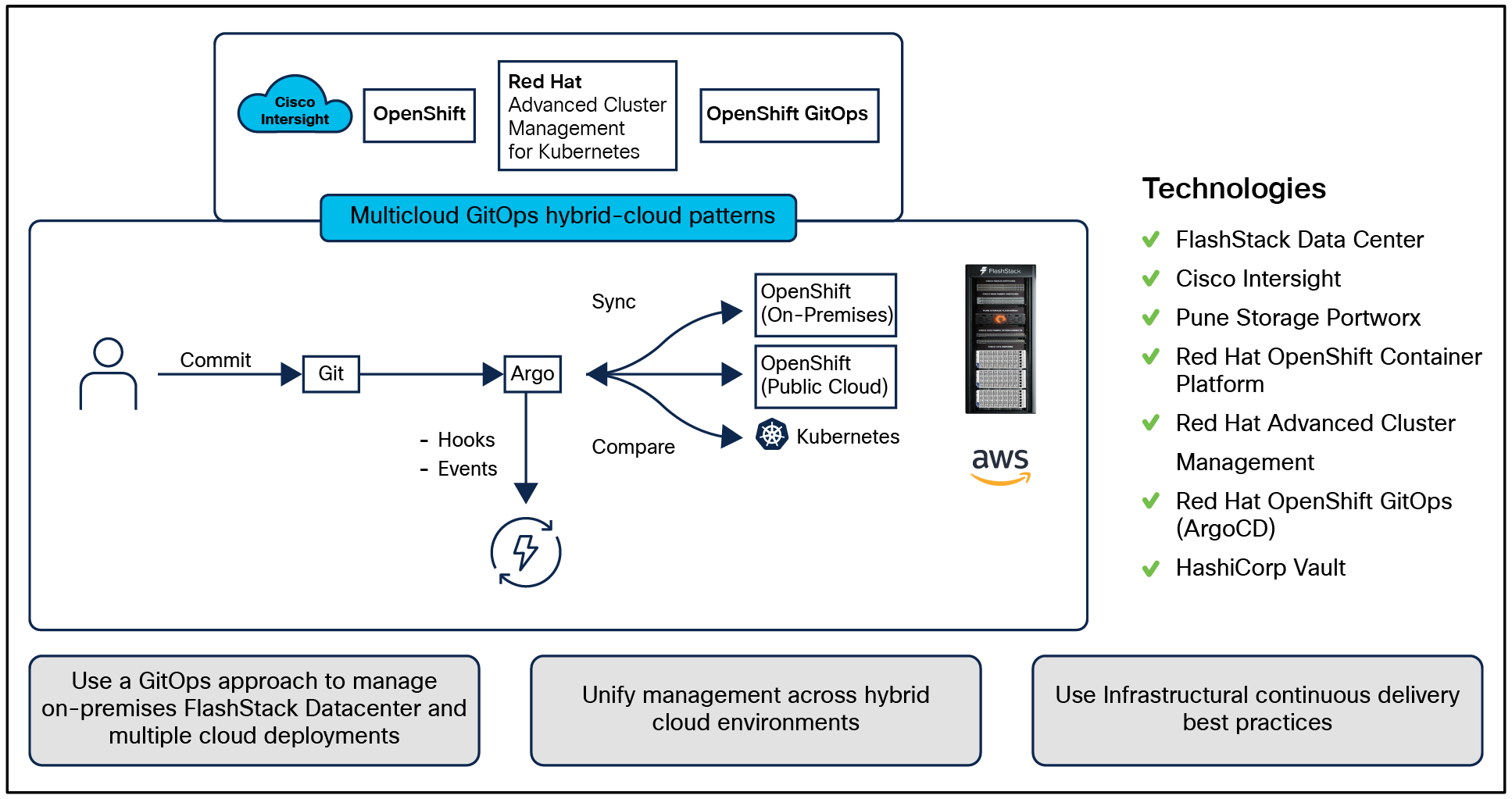
The solution presented in this document uses a GitOps approach to manage hybrid-cloud and multicloud deployments across on-premises and public cloud environments to provide cross-cluster governance and application lifecycle management on the Cisco® validated hybrid-cloud infrastructure solution for containerized workloads. This solution enables on-premises infrastructure provisioning at cloud scale with Cisco Intersight® powered by automation.
Validated patterns are living code architectures for different hybrid-cloud use cases. Validated patterns are used by architects and advanced developers to bring together products across the Red Hat® portfolio in a specific use case that are tested and maintained across the product lifecycle.
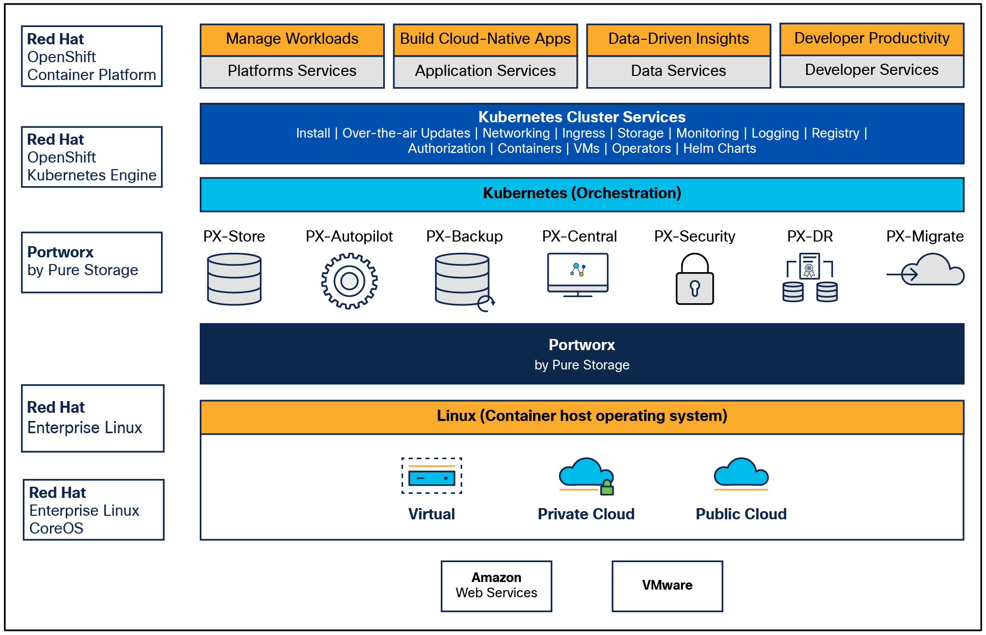
This paper explains the methodology to deploy the Red Hat validated pattern for Multicloud GitOps on a Cisco® validated hybrid-cloud infrastructure solution with Cisco UCS® X-Series based FlashStack Data Center, Red Hat OpenShift® Container Platform, Red Hat OpenShift GitOps, Red Hat Advanced Cluster Management for Kubernetes, and Portworx Enterprise Kubernetes Storage Platform.
On-premises infrastructure is built with FlashStack Virtual Server Infrastructure (VSI) with the Cisco UCS X-Series Modular System and managed using Cisco Intersight. The FlashStack solution is a validated, converged infrastructure developed jointly by Cisco and Pure Storage. The solution offers a predesigned data center architecture that incorporates computing, storage, and network design best practices to reduce IT risk by validating the architecture and helping ensure compatibility among the components. The FlashStack solution is successful because of its ability to evolve and incorporate both technology and product innovations in the areas of management, compute, storage, and networking.
The on-premises infrastructure deployment is automated using Red Hat Ansible® to provide infrastructure as code (IaC) that can be integrated into existing CI/CD pipelines or other automation to accelerate deployments.
Hybrid-cloud has become the de facto deployment and operating model in most enterprises. In a study conducted by 451 Research across 2500 organizations from around the globe, 82 percent of the IT decision makers responded that they are already using a hybrid-cloud model. Cloud computing from hyper scalers such as Amazon Web Services (AWS), Microsoft Azure, and Google Cloud offer limitless scale and flexibility, but it also comes with increasingly high costs, and sometimes higher risk, leaving enterprises with less control over their business critical applications and data. As a result, enterprises are adopting a hybrid strategy that allows them to optimally use both on-premises and public cloud infrastructure to meet their computing needs.
This solution covers hybrid and multicloud management with GitOps on the Cisco Validated Hybrid-cloud FlashStack‒based infrastructure solution for containerized workloads. At a high level, this requires a management hub, for DevOps and GitOps, and infrastructure that extends to one or more managed clusters running on-premises and/or public clouds. The automated infrastructure-as-code approach can manage the versioning of components and deploy according to the infrastructure-as-code configuration.
Solution overview
Benefits of hybrid multicloud management with GitOps on FlashStack‒based Cisco validated hybrid-cloud infrastructure solution include:
● Deployment of a Cisco validated hybrid-cloud infrastructure solution
● Infrastructure provisioning at cloud scale with Cisco Intersight powered by automation
● Unified management across cloud environments
● Dynamic infrastructure security
● Infrastructural continuous delivery best practices
● Multiple Cisco validated solutions on FlashStack Virtual Server Infrastructure
The reference architecture defined in this solution is built using Cisco X-Series modular‒based FlashStack, Cisco Intersight, Amazon Web Services (AWS), Red Hat OpenShift Container Platform (OCP), Red Hat OpenShift GitOps, Red Hat Advanced Cluster Management for Kubernetes, and Portworx Enterprise Storage Platform.
● Use a GitOps approach to manage hybrid and multicloud deployments across both public and private clouds
● Enable cross-cluster governance and application lifecycle management
● Securely manage secrets across the deployment
The intended audience of this document includes but is not limited to IT architects, sales engineers, field consultants, professional services, IT managers, partner engineering, and customers who are working on or interested in designing and deploying Cisco’s hybrid-cloud solutions.
This document provides architecture guidance to deploy and manage Multicloud GitOps validated patterns with Cisco FlashStack Data center on-premises. Hardware and software components used to validate the solution in Cisco’s internal labs are also provided. The document addresses various considerations and best practices for a successful deployment that enables enterprises to deploy applications using hybrid and Multicloud GitOps.
The OpenShift Container Platform deployment is done on Cisco UCS M6 platform servers (Cisco UCS X-Series compute nodes). But Cisco UCS M7 platform servers can also be leveraged.
Validated patterns are living code architectures for different edge computing and hybrid-cloud use cases deployed using a declarative GitOps framework. They are created by using GitOps to continuously deliver resources based on a defined distributed architecture. Validated patterns use operators to deploy applications and Helm Charts which are collections of files that describe sets of related Kubernetes resources for configuration that play a critical role in deploying distributed architectures, including Red Hat portfolio products with other technology ecosystem products, to help build a repeatable, reproducible solution architecture that can be extended across different platforms and delivery models, such as data centers, cloud platforms, and the edge. Validated patterns also incorporate a Continuous Integration (CI) pipeline to ensure that the use case continues to work across product updates to the ecosystem code base, providing consistency and trust as the lifecycle of the underlying products change over time. Using a validated pattern gives the confidence of using a best practice, reduces the risk of falling behind a crucial release point, and makes your deployment operable at scale.
These predefined computing configurations contain all the code necessary to build a comprehensive edge or hybrid-cloud stack. You can even create a pattern that goes beyond this documentation by using automated processes in GitOps that simplify deployment and ensure consistency across multiple sites and clusters. Each use case’s Git repository is open, and Red Hat regularly collaborates with customers to update use cases or to add partner technologies to configurations.
Validated patterns achieve the following, based on GitOps principles:
● Reproducibility: The declarative GitOps framework ensures that your applications do not fall out of sync with your desired state.
● Repeatability: Once the desired state has been created, it can be deployed at multiple locations and modified to support different infrastructure deployments.
● Lifecycle management: Validated patterns have their own lifecycle and are maintained over time, which allows for pattern versions to be tested based on new ecosystem product versions.
● Applicability: Each validated pattern includes a use case demo that shows how the pattern is being used in a real world scenario.
● Customizability: Validated patterns are meant to provide users with an accelerated time to value, delivering 80 percent or more of a desired deployment, As such, they incorporate a modular design so that architects can modify the pattern for their own use case and individual functions can be replaced to apply to other solutions.
Kubernetes provides a scalable orchestration platform for microservices and containers. Red Hat OpenShift, built on Kubernetes, enables organizations to build and deploy cloud native applications and use cases, extending workflows from the core to the edge. Incorporating applications, services and tools can greatly augment organizations’ ability to build workflows that significantly impact results; however, developing a distributed architecture with all of these collaborative technologies is not easy. Solution architects need to discover dependencies within products, how they interact with one another, and how they might change from version to version. Once an architecture is created, tested, and promoted to production, it is typically not repeatable, there is no consistency from one architecture to the next, and the architectures cannot be extended to other platforms or locations in short, the process is not scalable.
This is where validated patterns can help. Best practices and a deep understanding of how organizations are running patterns in their environments are the basis for a validated pattern. They help to operationalize a distributed architecture by using declarative GitOps principles and continuous integration pipelines. The result is an architecture that is built into code, so parts of the solution are built, deployed, and maintained together. The pattern framework can then be used to reproduce the solution and scale the solution across platforms; it can be repeated, modified, and extended for different workloads and use cases.
One benefit of using a validated pattern is that Red Hat maintains the configuration across product lifecycles, including testing against prerelease bits, assessing the interoperability of the distributed technologies as they evolve, so you can trust that the use case is going to work as intended.
Validated patterns also contain the code necessary to build your stack, and by using GitOps principles, developers can rely on automated processes to pinpoint more easily potential issues. A validated pattern makes the division of labor between various management pieces clear and easy to monitor and maintain.
Finally, patterns are developed using opensource principles, so they remain open and customizable. With validated patterns, known workloads can be replicated anywhere, with easy ways to modify the pattern for different use cases. As the technologies you use continue to improve and your use cases change, validated patterns can be automated and updated to suit your needs.
Validated pattern: Multicloud GitOps
Organizations are aiming to develop, deploy, and operate applications on an open hybrid-cloud in a stable, simple, and secure way. This hybrid strategy includes multicloud deployments where workloads might be running on multiple clusters and on multiple clouds, private or public. This strategy requires an infrastructure-as-code approach: GitOps. GitOps uses Git repositories as a single source of truth to deliver infrastructure as code. Submitted code checks the Continuous Integration (CI) process, while the Continuous Delivery (CD) process checks and applies requirements for such things as security, infrastructure as code, or any other boundaries set for the application framework. All changes to code are tracked, making updates easy while also providing version control should a rollback be needed.
The following technologies are used in this solution:
Red Hat OpenShift Platform
Red Hat OpenShift Platform is an enterprise ready Kubernetes container platform built for an open hybrid-cloud strategy. It provides a consistent application platform to manage hybrid-cloud, public cloud, and edge deployments. It delivers a complete application platform for both traditional and cloud native applications, allowing them to run anywhere. Red Hat OpenShift has a preconfigured, preinstalled, and self updating monitoring stack that provides monitoring for core platform components. It also enables the use of external secret management systems (for example, HashiCorp Vault in this case) to securely add secrets into the Red Hat OpenShift platform.
Red Hat OpenShift GitOps
Red Had OpenShift GitOps is a declarative application continuous delivery tool for Kubernetes based on the ArgoCD project. Application definitions, configurations, and environments are declarative, and version controlled in Git. It can automatically push the desired application state into a cluster, quickly find out if the application state is in sync with the desired state and manage applications in multicluster environments.
Red Hat Advanced Cluster Management for Kubernetes
Red Hat Advanced Cluster Management for Kubernetes controls clusters and applications from a single console, with built in security policies. It extends the value of Red Hat OpenShift by deploying applications, managing multiple clusters, and enforcing policies across multiple clusters at scale.
Red Hat Ansible Automation Platform
Red Hat Ansible Automation Platform provides an enterprise framework for building and operating IT automation at scale across hybrid-clouds, including edge deployments. It enables users across an organization to create, share, and manage automation, from development and operations to security and network teams.
Portworx Enterprise
Portworx Enterprise provides persistent storage and Kubernetes data services to Red Hat OpenShift. Persistence is necessary for stateful applications in Kubernetes environments. Portworx also provides business continuity with Portworx Backup and Portworx Disaster Recovery products that will be incorporated in a future GitOps pattern.
HashiCorp Vault
HashiCorp Vault prov ides a secure centralized store for dynamic infrastructure and applications across-clusters, including over low trust networks between clouds and data centers.
This solution also uses a variety of observability tools, including the Prometheus monitoring system and a Grafana dashboard, that are integrated with OpenShift, as well as components of the Observatorium metaproject, which includes Thanos and the Loki API.
The following figure provides a schematic diagram overview of the complete solution, including both components and data flows.
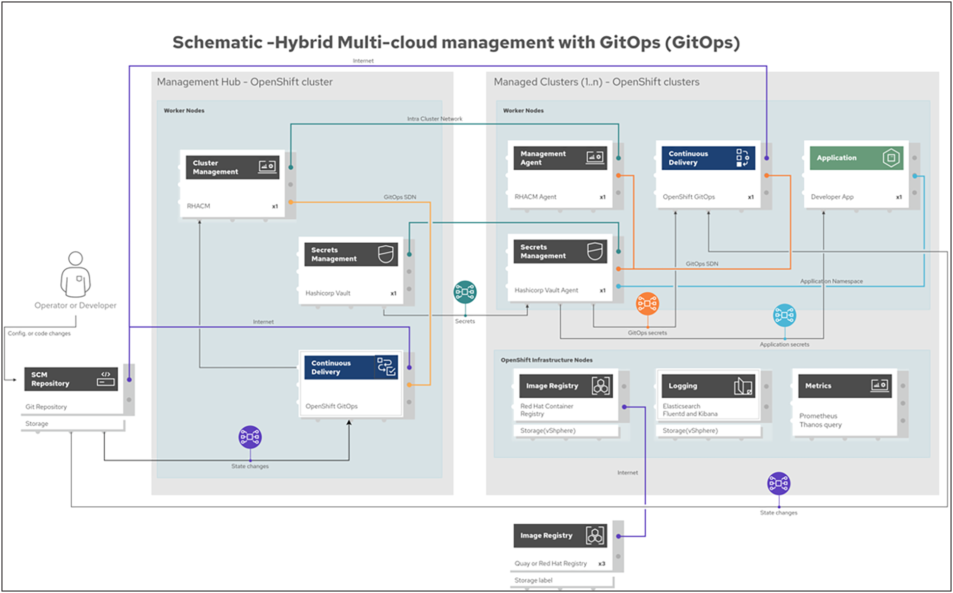
Schematic diagram
Cisco and Pure Storage have partnered to deliver many Cisco Validated Designs, which use best in class storage, server, and network components to serve as the foundation for virtualized workloads, enabling efficient architectural designs that you can deploy quickly and confidently.
FlashStack architecture is built using the following infrastructure components for compute, network, and storage (Figure 3):
● Cisco Unified Computing System (Cisco UCS)
● Cisco Nexus® switches
● Cisco MDS 9000 Series Multilayer Switches
● Pure Storage FlashArray
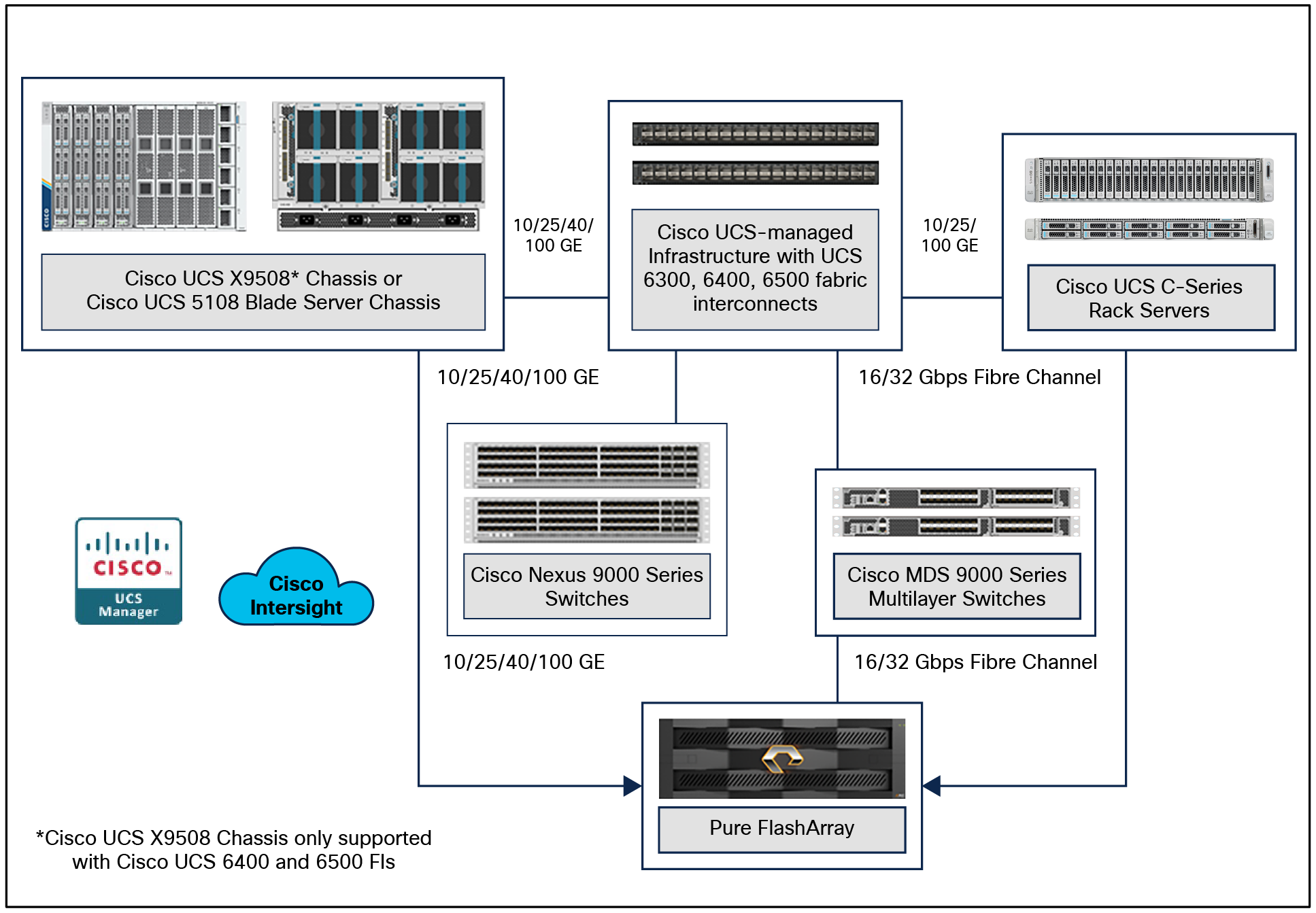
All FlashStack components are integrated, so customers can deploy the solution quickly and economically while eliminating many of the risks associated with researching, designing, building, and deploying similar solutions from the foundation. One of the main benefits of FlashStack is its ability to maintain consistency at scale. Each of the component families shown in Figure 4. (Cisco UCS, Cisco Nexus, Cisco MDS, and Pure Storage FlashArray systems) offers platform and resource options to scale up or scale out the infrastructure while supporting the same features and functions.
The FlashStack solution with Cisco UCS X-Series uses the following hardware components:
● Cisco UCS X9508 Chassis with any number of Cisco UCS X210c M6 Compute Nodes.
● Cisco UCS fourth generation 6454 fabric interconnects to support 25-and 100-GE connectivity from various components.
● High-speed Cisco NX-OS‒based Nexus 93180YC-FX3 switching designed to support up to 100-GE connectivity.
● Pure Storage FlashArray//XL170 with high-speed Ethernet or Fibre Channel connectivity.
● Pure FlashArray//XL170 storage with 25GbE connectivity to a Cisco Nexus switching fabric, and 32Gb FC connectivity to a Cisco MDS switching fabric.
The software components consist of:
● Cisco Intersight platform to deploy, maintain, and support the FlashStack components.
● Cisco Intersight Assist virtual appliance to help connect the Pure Storage FlashArray and VMware vCenter with the Cisco Intersight platform.
● For virtualized clusters, VMware vCenter 8.0 to set up and manage the virtual infrastructure as well as integration of the virtual environment with Cisco Intersight software.
Cisco Unified Computing System
Cisco Unified Computing System (Cisco UCS) is a next generation data center platform that integrates computing, networking, storage access, and virtualization resources into a cohesive system designed to reduce total cost of ownership and increase business agility. The system integrates a low latency, lossless 10-100 Gigabit Ethernet unified network fabric with enterprise class, x86-architecture servers. The system is an integrated, scalable, multichassis platform with a unified management domain for managing all resources.
Cisco Unified Computing System consists of the following subsystems:
● Compute – The compute piece of the system incorporates servers based on 2nd Generation Intel® Xeon® Scalable processors. Servers are available in blade and rack form factors, managed by Cisco UCS Manager.
● Network – The integrated network fabric in the system provides a low latency, lossless, 10/25/40/100 Gbps Ethernet fabric. Networks for LAN, SAN, and management access are consolidated within the fabric. The unified fabric uses the innovative single connect technology to lower costs by reducing the number of network adapters, switches, and cables. This in turn lowers the power and cooling needs of the system.
● Virtualization – The system unleashes the full potential of virtualization by enhancing the scalability, performance, and operational control of virtual environments. Cisco security, policy enforcement, and diagnostic features are now extended into virtual environments to support evolving business needs.
Cisco Unified Computing System is revolutionizing the way servers are managed in the data center. The following are the unique differentiators of Cisco Unified Computing System and Cisco UCS Manager:
● Embedded management – In Cisco UCS, the servers are managed by the embedded firmware in the fabric interconnects, eliminating the need for any external physical or virtual devices to manage the servers.
● Unified fabric – In Cisco UCS, from blade server chassis or rack servers to fabric interconnects, there is a single Ethernet cable used for LAN, SAN, and management traffic. This converged I/O results in reduced cables, SFPs and adapters – reducing capital and operational expenses of the overall solution.
● Auto discovery – By simply inserting the blade server into the chassis or connecting the rack server to the fabric interconnect, discovery and inventory of compute resources occurs automatically without any management intervention. The combination of unified fabric and auto discovery enables the wire once architecture of Cisco UCS, where the compute capability of Cisco UCS can be extended easily while keeping the existing external connectivity to LAN, SAN, and management networks.
Cisco UCS Manager (UCSM) provides unified, integrated management for all software and hardware components of Cisco UCS. Using Cisco® single connect technology, it manages, controls, and administers multiple chassis for thousands of virtual machines. Administrators use the software to manage the entire Cisco Unified Computing System as a single logical entity through an intuitive Graphical User Interface (GUI), a Command Line Interface (CLI), or through a robust Application Programming Interface (API).
Cisco UCS X-Series Modular System
The Cisco UCS X-Series Modular System is designed to take the current generation of the Cisco UCS platform to the next level with its design that will support future innovations and management in the cloud. Decoupling and moving platform management to the cloud allows the Cisco UCS platform to respond to features and scalability requirements much faster and more efficiently. Cisco UCS X-Series state of the art hardware simplifies the data center design by providing flexible server options. A single server type that supports a broader range of workloads results in fewer data center products to manage and maintain. The Cisco Intersight cloud management platform manages the Cisco UCS X-Series as well as integrating with third party devices. These devices include VMware vCenter and Pure Storage to provide visibility, optimization, and orchestration from a single platform, thereby enhancing agility and deployment consistency.
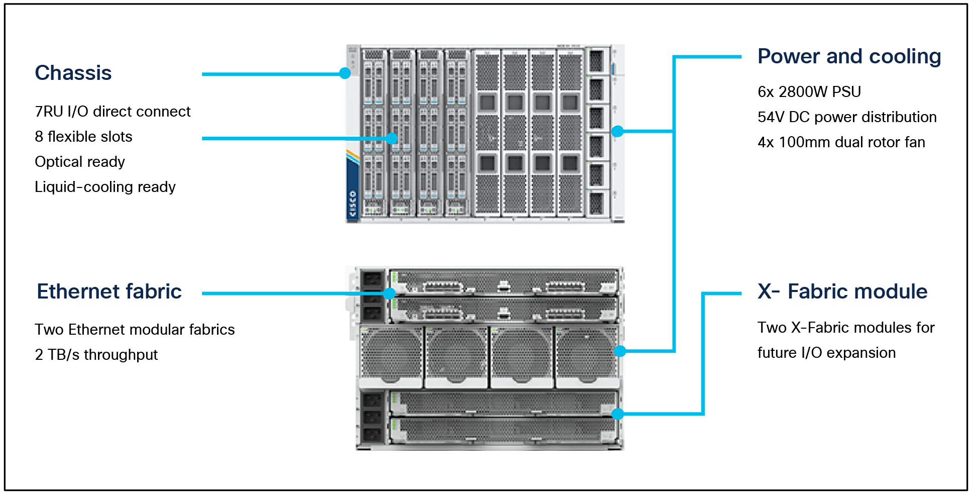
The Cisco UCS X9508 Chassis is engineered to be adaptable and flexible. As seen in Figure 5. the Cisco UCS X9508 has only a power distribution midplane. This innovative design provides fewer obstructions for better airflow. For I/O connectivity, vertically oriented compute nodes intersect with horizontally oriented fabric modules, allowing the chassis to support future fabric innovations. Cisco UCS X9508 Chassis’ superior packaging enables larger compute nodes, thereby providing more space for actual compute components, such as memory, GPUs, drives, and accelerators. Improved airflow through the chassis enables support for higher power components, and more space allows for future thermal solutions (such as liquid cooling) without limitations.
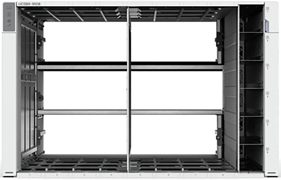
Cisco UCS X9508 Chassis – innovative design
The Cisco UCS X9508 7 rack unit (7RU) chassis has eight flexible slots. These slots can house a combination of compute nodes and a pool of future I/O resources that may include GPU accelerators, disk storage, and nonvolatile memory. At the top rear of the chassis are two Intelligent Fabric Modules (IFMs) that connect the chassis to upstream Cisco UCS 6400 Series Fabric Interconnects. At the bottom rear of the chassis are slots ready to house future UCS X-Fabric modules that can flexibly connect the compute nodes with I/O devices. Six 2800W Power Supply Units (PSUs) provide 54V power to the chassis with N, N+1, and N+N redundancy. A higher voltage allows efficient power delivery with less copper and reduced power loss. Efficient, 100mm, dual counter rotating fans deliver industry leading airflow and power efficiency, and optimized thermal algorithms enable different cooling modes to best support the customer’s environment.
Cisco UCSX 9108-25G Intelligent Fabric Modules
For the Cisco UCS X9508 Chassis, network connectivity is provided by a pair of Cisco UCSX 9108-25G Intelligent Fabric Modules (IFMs). Like the fabric extenders used in the Cisco UCS 5108 Blade Server Chassis, these modules carry all network traffic to a pair of Cisco UCS 6400 Series Fabric Interconnects (FIs). IFMs also host the Chassis Management Controller (CMC) for chassis management. In contrast to systems with fixed networking components, Cisco UCS X9508’s midplane free design enables easy upgrades to new networking technologies as they emerge, making it easier to accommodate new network speeds or technologies in the future.
![]()
Cisco UCSX 9108-25G Intelligent Fabric Module
Each IFM supports eight 25Gb uplink ports for connecting the Cisco UCS X9508 Chassis to the FIs and 32 25Gb server ports for the eight compute nodes. IFM server ports can provide up to 200 Gbps of unified fabric connectivity per compute node across the two IFMs. The uplink ports connect the chassis to the Cisco UCS FIs, providing up to 400Gbps connectivity across the two IFMs. The unified fabric carries management, VM, and Fibre Channel over Ethernet (FCoE) traffic to the FIs, where management traffic is routed to the Cisco Intersight cloud operations platform, FCoE traffic is forwarded to the native Fibre Channel interfaces through unified ports on the FI (to Cisco MDS switches), and data Ethernet traffic is forwarded upstream to the data center network (through Cisco Nexus switches).
Cisco UCSX 9108-100G Intelligent Fabric Modules
The Cisco UCS 9108-100G and 9108-25G Intelligent Fabric Module (IFM) brings the unified fabric into the blade server enclosure, providing connectivity between the blade servers and the fabric interconnect, simplifying diagnostics, cabling, and management.
This FlashStack solution with Cisco UCS X-Series and Cisco UCS 5th Generation Unified Fabric technology uses Cisco UCS 9108 100G IFM.
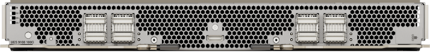
Cisco UCS X9108-100G Intelligent Fabric Module
The Cisco UCS 9108 100G IFM connects the I/O fabric between the Cisco UCS 6536 Fabric Interconnect and the Cisco UCS X9508 Chassis, enabling a lossless and deterministic converged fabric to connect all blades and chassis together. Because the fabric module is similar to a distributed line card, it does not perform any switching and is managed as an extension of the fabric interconnects. This approach removes switching from the chassis, reducing overall infrastructure complexity, and enabling Cisco UCS to scale to many chassis without multiplying the number of switches needed, reducing TCO and allowing all chassis to be managed as a single, highly available management domain. The Cisco UCS 9108 100G IFM also manages the chassis environment (power supply, fans, and blades) in conjunction with the fabric interconnect. Therefore, separate chassis management modules are not required.
The IFM plugs into the rear side of the Cisco UCS X9508 Chassis. The IFM provides a data path from the chassis compute nodes to the Cisco UCS 6536 Fabric Interconnect. Up to two Intelligent Fabric Modules (IFMs) plug into the back of the Cisco UCS X9508 Chassis.
The IFMs serve as line cards in the chassis and multiplex data from the compute nodes to the Fabric Interconnect (FI). They also monitor and manage chassis components such as fan units, power supplies, environmental data, the LED status panel, and other chassis resources. The server compute node Keyboard, Video, and Mouse (KVM) data, Serial over LAN (SoL) data, and intelligent Platform Management Interface (IPMI) data also travel to the IFMs for monitoring and management purposes. In order to provide redundancy and failover, the IFMs are always used in pairs.
There are 8 x QSFP28 external connectors on an IFM to interface with a Cisco UCS 6536 Fabric Interconnect. The IFM internally provides 1 x 100G or 4 x 25G connections toward each Cisco UCS X210c Compute Node in the Cisco UCS X9508 Chassis.
Cisco UCS X210c M6 Compute Node
The Cisco UCS X9508 Chassis is designed to host up to 8 Cisco UCS X210c M6 Compute Nodes. The hardware details of the Cisco UCS X210c M6 Compute Nodes are shown in Figure 8.
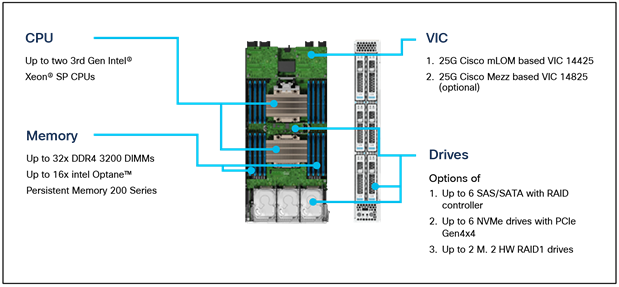
Cisco UCS X210c M6 Compute Node
The Cisco UCS X210c M6 Compute Node features:
● CPU: Up to 2x 3rd Gen Intel Xeon Scalable Processors with up to 40 cores per processor and 1.5 MB Level 3 cache per core
● Memory: Up to 32 x 256 GB DDR4-3200 DIMMs for a maximum of 8 TB of main memory. The UCS X210c M6 can also be configured for up to 16 x 512-GB Intel Optane persistent memory DIMMs for a maximum of 12 TB of memory.
● Disk storage: Up to 6 SAS or SATA drives can be configured with an internal RAID controller, or customers can configure up to 6 NVMe drives. 2 M.2 memory cards can be added to the UCS X210c M6 with RAID 1 mirroring.
● Virtual interface card (VIC): Up to 2 VICs, including an mLOM Cisco UCS VIC 14425 and a mezzanine Cisco UCS VIC 14825, can be installed in a UCS X210c M6.
● Security: The server supports an optional Trusted Platform Module (TPM). Additional security features include a secure boot FPGA and ACT2 anticounterfeit provisions.
Cisco UCS Virtual Interface Cards (VICs)
Cisco UCS X210c M6 Compute Nodes support the following Cisco fourth generation VICs:
Cisco UCS VIC 14425 fits the mLOM slot in the Cisco UCS X210c M6 Compute Node and enables up to 50 Gbps of unified fabric connectivity to each of the chassis IFMs for a total of 100 Gbps of connectivity per server. Cisco UCS VIC 14425 connectivity to the IFM and fabric interconnects is delivered through 4x 25-Gbps connections, which are configured automatically as 2x 50-Gbps port channels. The Cisco UCS VIC 14425 supports 256 virtual interfaces (both Fibre Channel and Ethernet) along with the latest networking innovations, such as NVMe-oF over RDMA (ROCEv2), VxLAN/NVGRE offload, and so on.
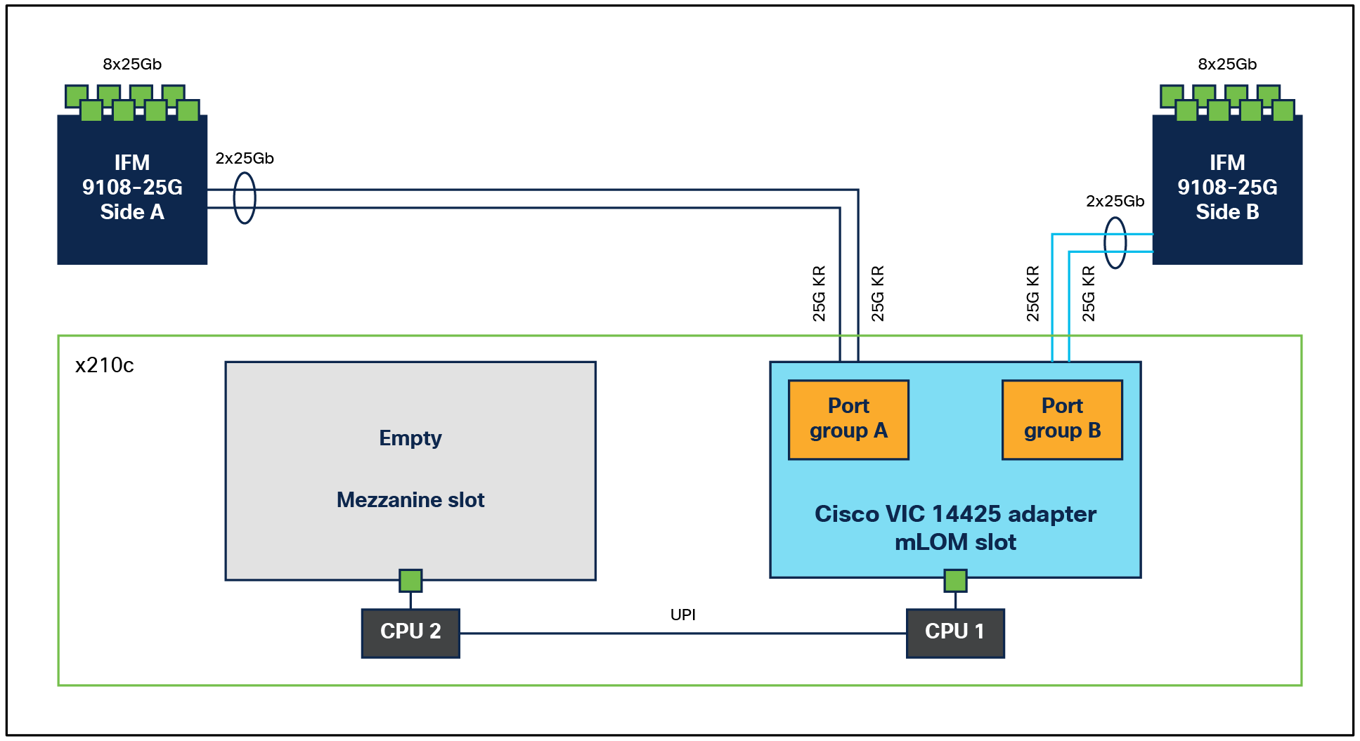
Single Cisco UCS VIC 14425 in Cisco UCS X210c M6 Compute Node
The connections between the 4th generation Cisco UCS VIC 1440 in the Cisco UCS B200 Blade Servers and the I/O modules in the Cisco UCS 5108 Blade Server Chassis comprise multiple 10Gbps KR lanes. The same connections between Cisco UCS VIC 14425 and IFMs in the Cisco UCS X-Series comprise multiple 25Gbps KR lanes, resulting in 2.5x better connectivity in Cisco UCS X210c M6 Compute Nodes.
The optional Cisco UCS VIC 14825 fits the mezzanine slot on the server. A bridge card (UCSX-V4-BRIDGE) extends this VIC’s 2x 50 Gbps of network connections up to the mLOM slot and out through the mLOM’s IFM connectors, bringing the total bandwidth to 100 Gbps per fabric for a total bandwidth of 200 Gbps per server.
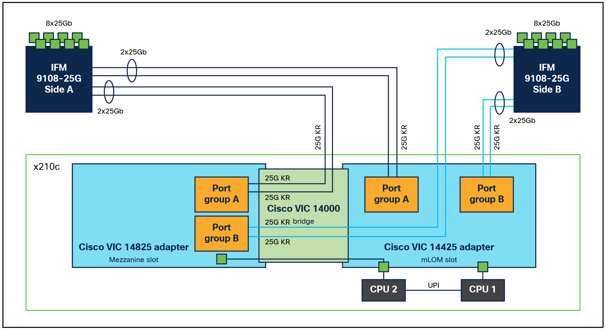
Cisco UCS VIC 14425 and 14825 in Cisco UCS X210c M6 Compute Node
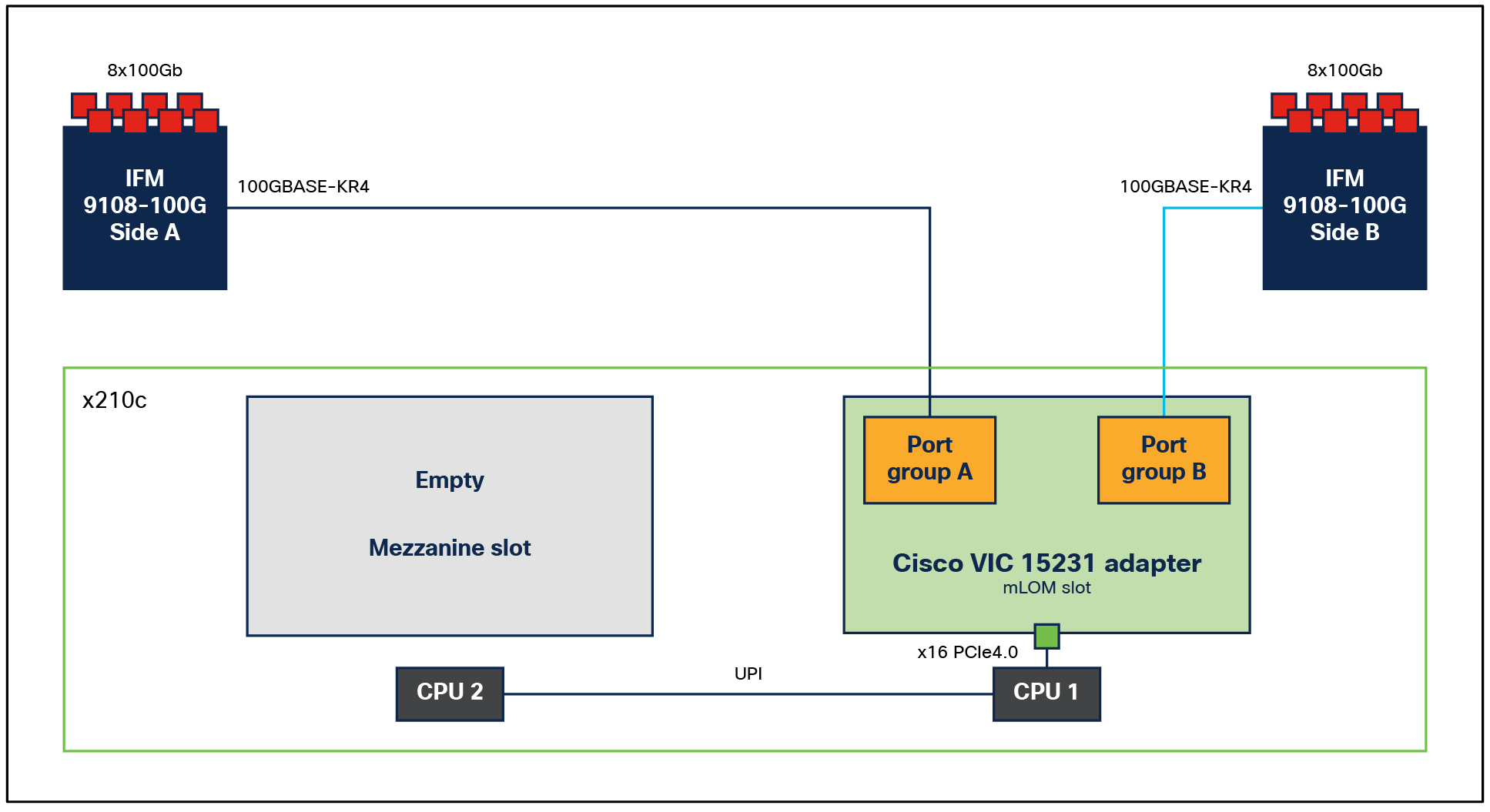
Cisco UCS VIC 15231 fits the mLOM slot in the Cisco X210c M6 Compute Node and enables up to 100 Gbps of unified fabric connectivity to each of the chassis IFMs for a total of 200 Gbps of connectivity per server.
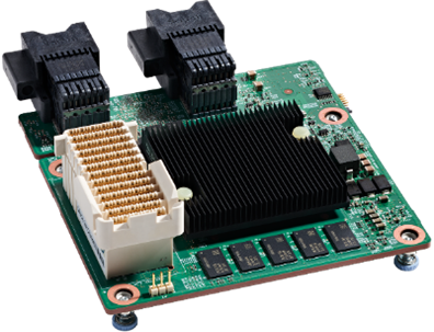
Cisco UCS VIC 15231 mLOM
Cisco UCS VIC 15231 connectivity to the IFM and up to the fabric interconnects is delivered through 2x 100-Gbps connections. Cisco UCS VIC 15231 supports 256 virtual interfaces (both Fibre Channel and Ethernet) along with the latest networking innovations such as NVMeoF over RDMA (ROCEv2), VxLAN/NVGRE/GENEVE offload, and so on.
Single Cisco VIC 15231 in Cisco UCS X210c M6 Compute Node
The connections between Cisco UCS VIC 15231 and IFMs in the Cisco UCS X-Series results in 2x better connectivity in Cisco UCS X210c M6 Compute Nodes compared to the 4th generation Cisco UCS VIC 14425 in the Cisco UCS x210 M6 Compute Nodes.
The network interface speed comparison between VMware ESXi installed on a Cisco UCS B200 M5 Blade Server with a Cisco UCS VIC 1440, a Cisco UCS X210c M6 Compute Node with a Cisco UCS VIC 14425, and a Cisco UCS X210c M6 Compute Node with a Cisco UCS VIC 15231 are shown in Figure 13.

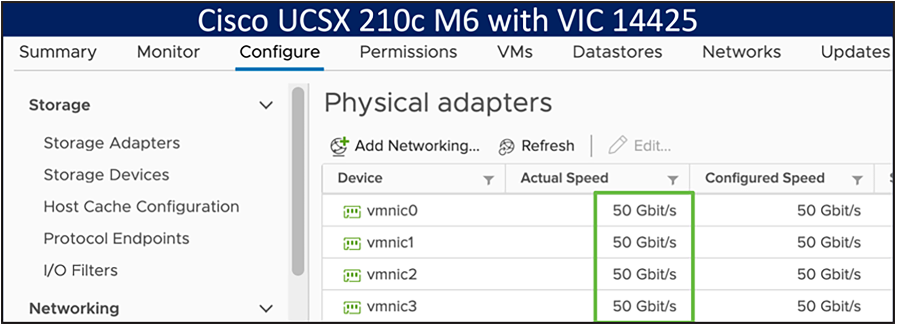
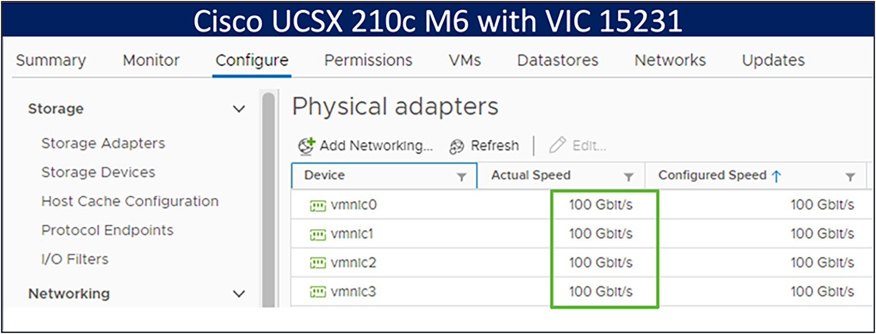
Network interface speed comparison
Cisco UCS 6400 Series Fabric Interconnects
The Cisco UCS Fabric Interconnects (FIs) provide a single point of connectivity and management for the entire Cisco UCS system. Typically deployed as an active/active pair, the system’s FIs integrate all components into a single, highly available management domain controlled by the Cisco UCS Manager or Cisco Intersight. Cisco UCS FIs provide a single unified fabric for the system, with low latency, lossless, cut through switching that supports LAN, SAN, and management traffic using a single set of cables.
![]()
Cisco UCS 6454 Fabric Interconnect
The Cisco UCS 6454 utilized in the current design is a 54-port fabric interconnect. This single-RU device includes 28 10/25 Gbps Ethernet ports, 4 1/10/25-Gbps Ethernet ports, 6 40/100-Gbps Ethernet uplink ports, and 16 unified ports that can support 10/25 Gigabit Ethernet or 8/16/32-Gbps Fibre Channel, depending on the SFP.
Note: For supporting the Cisco UCS X-Series, the fabric interconnects must be configured in Cisco Intersight Managed Mode (IMM). This option replaces the local management with Cisco Intersight cloud or appliance based management.
5th Generation Cisco UCS Fabric Interconnects
The Cisco UCS Fabric Interconnects (FIs) provide a single point of connectivity and management for the entire Cisco UCS system. Typically deployed as an active/active pair, the system’s FIs integrate all components into a single, highly available management domain controlled by the Cisco UCS Manager or Cisco Intersight. Cisco UCS FIs provide a single unified fabric for the system, with low latency, lossless, cut through switching that supports LAN, SAN, and management traffic using a single set of cables.
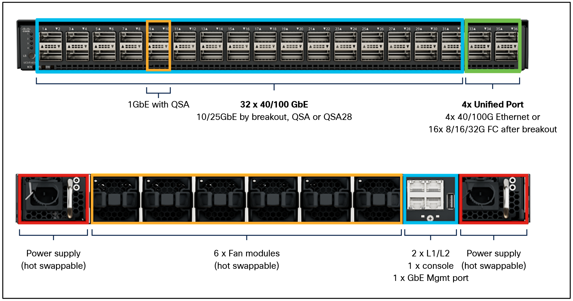
Cisco UCS 6536 Fabric Interconnect – front and rear view
The Cisco UCS 6536 Fabric Interconnect utilized in the current design is a one Rack Unit (1RU) 1/10/25/40/100 Gigabit Ethernet, FCoE, and Fibre Channel (FC) switch offering up to 7.42 Tbps throughput and up to 36 ports. The switch has 32 40/100-Gbps Ethernet ports and 4 unified ports that can support 40/100-Gbps Ethernet ports or 16 Fiber Channel ports after breakout at 8/16/32-Gbps FC speeds. The 16 FC ports after breakout can operate as FC uplinks or FC storage ports. The switch also supports two ports at 1-Gbps speed using QSA, and all 36 ports can break out for 10-or 25-Gbps Ethernet connectivity. All Ethernet ports can support FCoE.
The Cisco UCS 6536 Fabric Interconnect (FI) is a core part of the Cisco Unified Computing System, providing both network connectivity and management capabilities for the system. The Cisco UCS 6536 Fabric Interconnect offers line rate, low latency, lossless 10/25/40/100 Gigabit Ethernet, Fibre Channel, NVMe over Fabric, and Fibre Channel over Ethernet (FCoE) functions.
The Cisco UCS 6536 Fabric Interconnect provides the communication backbone and management connectivity for the Cisco UCS X-Series compute nodes, Cisco UCS X9508 Chassis, Cisco UCS B-series blade servers, Cisco UCS 5108 B-series server chassis, and Cisco UCS C-series rack servers. All servers attached to a Cisco UCS 6536 Fabric Interconnect become part of a single, highly available management domain. In addition, by supporting a unified fabric, Cisco UCS 6536 Fabric Interconnect provides both LAN and SAN connectivity for all servers within its domain.
From a networking perspective, the Cisco UCS 6536 uses a cut through architecture, supporting deterministic, low latency, line rate 10/25/40/100 Gigabit Ethernet ports, a switching capacity of 7.42 Tbps per FI and 14.84 Tbps per unified fabric domain, independent of packet size and enabled services. It enables 1600Gbps bandwidth per UCS X9508 chassis with X9108-IFM-100G in addition to enabling end-to-end 100G ethernet and 200G aggregate bandwidth per UCS X210c compute node. With the X9108-IFM-25G and the IOM 2408, it enables 400Gbps bandwidth per chassis per FI domain. The product family supports Cisco low latency, lossless 10/25/40/100 Gigabit Ethernet unified network fabric capabilities, which increases the reliability, efficiency, and scalability of Ethernet networks. The UCS 6536 Fabric Interconnect supports multiple traffic classes over a lossless Ethernet fabric from the server through the fabric interconnect. Significant TCO savings come from the unified fabric‒optimized server design in which Network Interface Cards (NICs), Host Bus Adapters (HBAs), cables, and switches can be consolidated.
Cisco UCS unified fabric: I/O consolidation
The Cisco UCS 6536 Fabric Interconnect is built to consolidate LAN and SAN traffic onto a single unified fabric, saving on Capital Expenditures (CapEx) and Operating Expenses (OpEx) associated with multiple parallel networks, different types of adapter cards, switching infrastructure, and cabling within racks. The unified ports allow ports in the fabric interconnect to support direct connections from Cisco UCS to existing native Fibre Channel SANs. The capability to connect to a native Fibre Channel protects existing storage system investments while dramatically simplifying in rack cabling.
The Cisco UCS 6536 Fabric Interconnect supports I/O consolidation with end-to-end network virtualization, visibility, and Quality-of-Service (QoS) enables the following LAN and SAN traffic:
● FC SAN, IP storage (iSCSI, NFS), NVMEoF (NVMe/FC, NVMe/TCP, NVMe over ROCEv2)
● Server management and LAN traffic
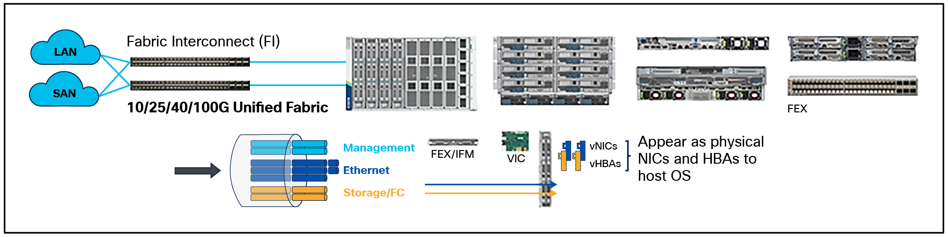
Cisco UCS unified fabric
The I/O consolidation under the Cisco UCS 6536 Fabric Interconnect, along with the stateless policy driven architecture of Cisco UCS and the hardware acceleration of the Cisco UCS virtual interface card, provides great simplicity, flexibility, resiliency, performance, and TCO savings for the customer’s compute infrastructure.
As applications and data become more distributed from the core data center and edge locations to public clouds, a centralized management platform is essential. IT agility will be a struggle without a consolidated view of infrastructure resources and centralized operations. Cisco Intersight provides a cloud hosted management and analytics platform for all Cisco UCS and other supported third party infrastructure across the globe. It provides an efficient way of deploying, managing, and upgrading infrastructure in the data center and remote or branch offices, at the edge, and in colocation environments.
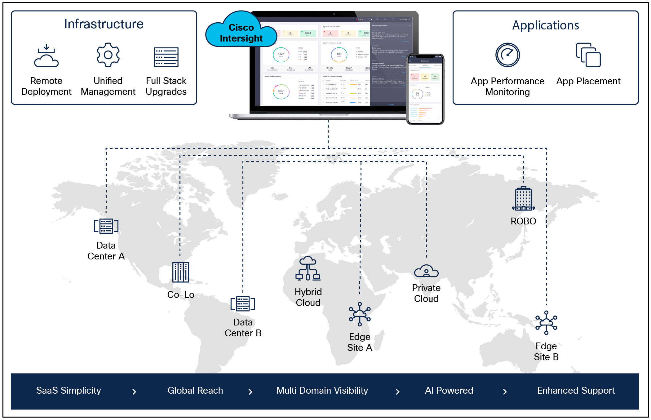
Cisco Intersight
Cisco Intersight provides:
● No impact transition: An embedded connector within Cisco UCS will allow customers to start consuming benefits without a forklift upgrade.
● SaaS/subscription model: SaaS model provides for centralized, cloud scale management and operations across hundreds of sites around the globe without the administrative overhead of managing the platform.
● Enhanced support experience: A hosted platform allows Cisco to address issues platform wide, and this experience extends into platform supported by Cisco Technical Assistance Center (Cisco TAC).
● Unified management: A single pane of glass and a consistent operations model provide experience for managing all systems and solutions in one place.
● Programmability: End-to-end programmability with native APIs, SDKs, and popular DevOps toolsets will enable customers to consume natively.
● Single point of automation: Automation using Red Hat Ansible, HashiCorp Terraform, and other tools can be done through Intersight for all systems it manages.
● Recommendation engine: Our approach, which includes visibility, insight and action powered by machine intelligence and analytics, provides real time recommendations with agility and scale. An embedded recommendation engine offers insights sourced from across the network and tailored to each customer.
The main benefits of Cisco Intersight infrastructure services are as follows:
● Simplify daily operations by automating many daily manual tasks.
● Combine the convenience of a SaaS platform with the capability to connect from anywhere and manage infrastructure through a browser or mobile app.
● Stay ahead of problems and accelerate trouble resolution through advanced support capabilities.
● Gain global visibility of infrastructure health and status along with advanced management and support capabilities.
● Upgrade to add workload optimization when needed.
In this solution, Cisco Intersight unifies and simplifies the hybrid-cloud operations of FlashStack Data center components wherever they are deployed.
Cisco Intersight Virtual Appliance and Private Virtual Appliance
In addition to the SaaS deployment model running on Intersight.com, on-premises options can be purchased separately. The Cisco Intersight Virtual Appliance and Cisco Intersight Private Virtual Appliance are available for organizations that have additional data locality or security requirements for managing systems. The Cisco Intersight Virtual Appliance delivers the management features of the Cisco Intersight platform in an easy to deploy VMware Open Virtual Appliance (OVA) or Microsoft Hyper-V Server virtual machine that allows you to control the system details that leave your premises. The Cisco Intersight Private Virtual Appliance is provided in a form factor specifically designed for users who operate in disconnected (air gap) environments. The Private Virtual Appliance requires no connection to public networks or back to Cisco to operate.
Cisco Intersight Assist and Device Connectors
Cisco Intersight Assist helps customers add endpoint devices to Cisco Intersight. A data center could have multiple devices that do not connect directly with Cisco Intersight. Any device that is supported by Cisco Intersight but does not connect to Intersight directly needs Cisco Intersight Assist to provide the necessary connectivity. FlashStack, VMware vCenter, and Pure Storage FlashArray connect to Intersight with the help of the Intersight Assist appliance.
Cisco Intersight Assist is available within the Cisco Intersight Virtual Appliance, which is distributed as a deployable virtual machine contained within an Open Virtual Appliance (OVA) file format. More details about the Cisco Intersight Assist VM deployment configuration is covered in later sections.
Cisco Intersight integrates with VMware vCenter and Pure Storage FlashArray as follows:
● Cisco Intersight uses the device connector running within the Cisco Intersight Assist virtual appliance to communicate with the VMware vCenter.
● Cisco Intersight uses the device connector running within a Cisco Intersight Assist virtual appliance to integrate with Pure Storage FlashArray//XL170.
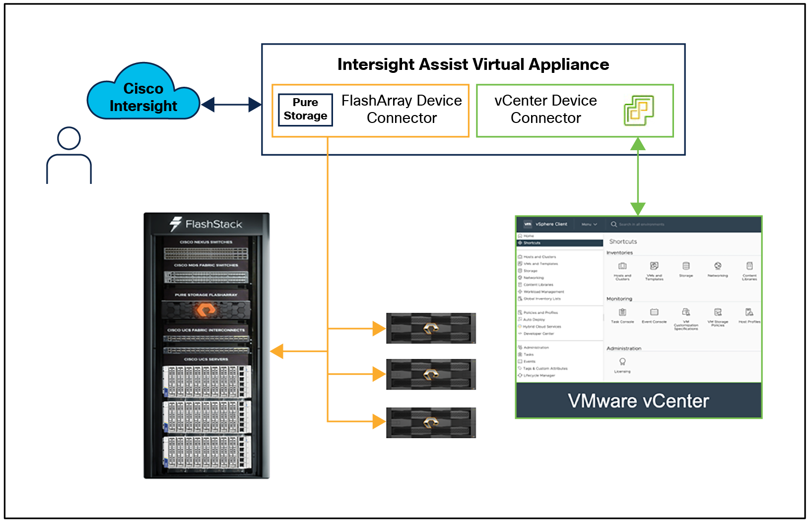
Cisco Intersight and vCenter and Pure Storage integration
The device connector provides a safe way for connected targets to send information and receive control instructions from the Cisco Intersight portal using a secure Internet connection. The integration brings the full value and simplicity of Cisco Intersight infrastructure management service to VMware hypervisor and FlashArray storage environments. The integration architecture enables FlashStack customers to use new management capabilities with no compromise in their existing VMware or FlashArray operations. IT users will be able to manage heterogeneous infrastructure from a centralized Cisco Intersight portal. At the same time, the IT staff can continue to use VMware vCenter and the Pure Storage dashboard for comprehensive analysis, diagnostics, and reporting of virtual and storage environments. The next section addresses the functions that this integration provides.
Cisco Nexus 9000 Series Switches
The Cisco Nexus 9000 Series Switches offer both modular and fixed 1/10/25/40/100 Gigabit Ethernet switch configurations with scalability up to 60 Tbps of nonblocking performance with less than five microsecond latency, wire speed VXLAN gateway, bridging, and routing support.
![]()
Cisco Nexus 93180YC-FX3 Switch
The Cisco Nexus 9000 Series Switch featured in this design is the Cisco Nexus 93180YC-FX3 configured in Cisco NX-OS standalone mode. Cisco NX-OS is a purpose built data center operating system designed for performance, resiliency, scalability, manageability, and programmability at its foundation. It provides a robust and comprehensive feature set that meets the demanding requirements of virtualization and automation.
The Cisco Nexus 93180YC-FX3 switch is a 1RU switch that supports 3.6 Tbps of bandwidth and 1.2 bpps. The 48 downlink ports on the 93180YC-FX3 can support 1-, 10-, or 25-Gbps Ethernet, offering deployment flexibility and investment protection. The six uplink ports can be configured as 40- or 100-Gbps Ethernet, offering flexible migration options.
Cisco MDS 9132T 32G Multilayer Fabric Switch
The Cisco MDS 9132T 32G Multilayer Fabric Switch is the next generation of the highly reliable, flexible, and low cost Cisco MDS 9100 Series switches. It combines high performance with exceptional flexibility and cost effectiveness. This powerful, compact one Rack Unit (1RU) switch scales from 8 to 32 line rate 32 Gbps Fibre Channel ports.
![]()
Cisco MDS 9132T 32G Multilayer Fabric Switch
The Cisco MDS 9132T delivers advanced storage networking features and functions with ease of management and compatibility with the entire Cisco MDS 9000 family portfolio for reliable end-to-end connectivity. This switch also offers state of the art SAN analytics and telemetry capabilities that have been built into this next generation hardware platform. This new state of the art technology couples the next generation port Cisco ASIC with a fully dedicated network processing unit designed to complete analytics calculations in real time. The telemetry data extracted from the inspection of the frame headers are calculated on board (within the switch) and, using an industry leading open format, can be streamed to any analytics visualization platform. This switch also includes a dedicated 10/100/1000BASE-T telemetry port to maximize data delivery to any telemetry receiver, including Cisco Data center Network Manager.
Red Hat OpenShift Container Platform
The Red Hat OpenShift Container Platform (OCP) is a container application platform that brings together CRI-0 and Kubernetes and provides an API and web interface to manage these services. CRI-O is a light weight implementation of the Kubernetes CRI (container runtime interface) to enable using Open Container Initiative (OCI)‒compatible runtimes including runC, crun, and Kata containers.
OCP allows customers to create and manage containers. Containers are standalone processes that run within their own environment, independent of the operating system and the underlying infrastructure. OCP helps develop, deploy, and manage container based applications. It provides a self service platform to create, modify, and deploy applications on demand, thus enabling faster development and release life cycles. OCP has a microservices based architecture of smaller, decoupled units that work together. It is powered by Kubernetes with data about the objects stored in etcd, a reliable clustered key value store.
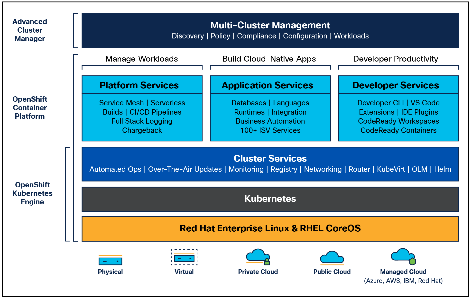
OpenShift Container Platform overview
Some of the capabilities in Red Hat OCP include:
● Automated deployment of OCP clusters on-premises (bare metal, VMware vSphere, Red Hat Open Stack Platform, and Red Hat Virtualization) and in public clouds.
● Automated upgrades of OCP clusters with seamless over the air upgrades initiated from the web console or OpenShift CLI (oc).
● Add services with push button ease: Once a cluster is deployed, Red Hat OpenShift uses Kubernetes operators to deploy additional capabilities and services on the cluster. Red Hat Certified and community supported operators are available in the embedded operator hub and can be deployed with the click of a button.
● Multicluster management using Red Hat’s cloud based Hybrid-cloud Console or enterprise managed Advance Cluster Management (ACM) provides a consolidated view of all clusters, with the ability to easily access and use other Kubernetes technologies and services. OCP clusters can also be individually managed using a web based cluster console or APIs.
● Persistent storage support: OCP provides support for a broad range of ecosystem storage partners including the Portworx Enterprise Storage Platform used in this solution.
● Scalability: OCP can scale to meet the largest and smallest compute use cases as needed.
● Automate container and application builds, deployments, scaling, cluster management, and more with ease.
● Self-service provisioning: Developers can quickly and easily create applications on demand from the tools they use most, while operations retain full control over the entire environment.
● Source-to-image deployment: OCP provides a toolkit and workflow for producing ready to run images by injecting source code into a container and letting the container prepare that source code for execution.
For more information, see: Red Hat OpenShift Container Platform product page on redhat.com.
Within OpenShift Container Platform, Kubernetes manages containerized applications across a set of CRI-O runtime hosts and provides mechanisms for deployment, maintenance, and application scaling. The CRI-O service packages, instantiates, and runs containerized applications.
A Kubernetes cluster consists of one or more control plane nodes and a set of worker nodes. This solution design includes HA functionality at the hardware as well as the software stack. An OCP cluster is designed to run in HA mode with three control plane nodes and a minimum of two worker nodes to help ensure that the cluster has no single point of failure.
Red Hat Hybrid-cloud Console is a centralized SaaS based management console for deploying and managing multiple OCP clusters. It is used in this solution to provide consistent container management across a hybrid environment. The SaaS model enables enterprises to develop, deploy, and innovate faster across multiple infrastructures and quickly take advantage of new capabilities without the overhead of managing the tool. The console gives enterprises more control and visibility as environments grow and scale. The Hybrid-cloud Console also provides tools to proactively address issues, open and manage support cases, manage cloud costs, subscriptions, and more.
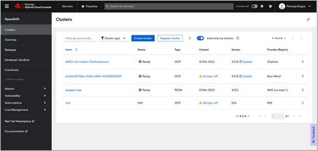
Red Hat Hybrid-cloud Console Dashboard
For more information, see: Red Hat Hybrid-cloud Console product page on redhat.com.
Red Hat OpenShift is available as a managed service by Red Hat and major cloud providers or as a self managed service where the enterprise manages and maintains the OCP cluster. Red Hat OCP as a managed service is hosted on major public clouds with Red Hat’s expert SRE teams providing a fully managed application platform, enabling the enterprise to focus on its applications and core business. Red Hat OpenShift is a complete, production ready application platform with additional services such as CI/CD pipelines, monitoring, security, container registry, service mesh, and more included on top of Kubernetes. OpenShift services include Red Hat OpenShift Service on AWS, Microsoft Azure Red Hat OpenShift, Red Hat OpenShift Dedicated on Google Cloud or AWS, and Red Hat OpenShift on IBM Cloud.
Red Hat Enterprise Linux CoreOS (RHCOS) is deployed automatically using configurations in the ignition files. The OCP installer creates the ignition configuration files necessary to deploy the OCP cluster with RHCOS. The configuration is based on the user provided responses to the installer. These files and images are downloaded and installed on the underlying infrastructure by the installer.
● Openshift install is a command line utility for installing OCP in cloud environments and on-premises. It collects information from the user, generates manifests, and uses Terraform to provision and configure infrastructure that will compose a cluster.
● Assisted installer is a cloud hosted installer available at https://console.redhat.com as both an API and a guided web UI. After defining a cluster, the user downloads a custom “discovery ISO” and boots it on the systems that will be provisioned into a cluster, at which point each system connects to console.redhat.com for coordination. Assisted installer offers great flexibility and customization while ensuring success by running an extensive set of validations prior to installation.
● Agent based installer is a command line utility that delivers the functionality of Assisted Installer in a standalone format that can be run in disconnected and air gapped environments, creating a cluster without requiring any other running systems besides a container registry.
● Red Hat Advanced Cluster Management for Kubernetes (see the section below) includes Assisted Installer running on-premises behind a Kubernetes API in addition to a web UI. OpenShift’s bare metal platform features, especially the bare metal operator, can be combined with Assisted installer to create an integrated end-to-end provisioning flow that uses Redfish Virtual Media to automatically boot the discovery ISO on managed systems.
Red Hat Enterprise Linux CoreOS
Red Hat Enterprise Linux CoreOS (RHCOS) is a lightweight operating system specifically designed for running containerized workloads. It is based on the secure, enterprise grade Red Hat Enterprise Linux (RHEL). RHCOS is the default operating system on all Red Hat OCP cluster nodes. RHCOS is tightly controlled, allowing only a few system settings to be modified using the ignition configuration files. RHCOS is designed to be installed as part of an OCP cluster installation process with minimal user configuration. Once the cluster is deployed, the cluster will fully manage the RHCOS subsystem configuration and upgrades.
RHCOS includes:
● Ignition: for initial bootup configuration and disk related tasks on OCP cluster nodes
Ignition serves as a first boot system configuration utility for initially bringing up and configuring the nodes in the OCP cluster. Starting from a tightly controlled OS image, the complete configuration of each system is expressed and applied using ignition. It also creates and formats disk partitions, writes files, creates file systems and directories, configures users, etc. During a cluster install, the control plane nodes get their configuration files from the temporary bootstrap machine used during install, and the worker nodes get theirs from the control plane nodes. After an OCP cluster is installed, subsequent configurations of nodes are done using the Machine Config Operator to manage and apply ignition.
● CRI-O: container engine running on OCP cluster nodes
CRI-O is a stable, standards based, lightweight container engine for Kubernetes that runs and manages the containers on each node. CRI-O implements the Kubernetes Container Runtime Interface (CRI) for running Open Container Initiative (OCI) compliant runtimes. OCP’s default container runtime is runC. CRI-O has a small footprint and a small attack surface, with an emphasis on security and simplicity. CRI-O is a Cloud Native Computing Foundation (CNCF) incubating project.
● Kubelet: Kubernetes service running on OCP cluster nodes
Kubelet is a Kubernetes service running on every node in the cluster. It communicates with the control plane components and processes requests for running, stopping, and managing container workloads.
● Container tools
RHCOS includes a set of container tools (including Podman, Skopeo, and crictl) for managing containers and container image actions such as start, stop, run, list, remove, build, sign, push, and pull.
● rpm-ostree combines RPM package management with libostree’s immutable content addressable operating system image management. RHCOS is installed and updated using libostree, guaranteeing that the installed OS is in a known state, with transactional upgrades and support for rollback.
Note: RHCOS was used on all control planes and worker nodes to support the automated Red Hat OpenShift 4 deployment.
Red Hat Advanced Cluster Management for Kubernetes
Red Hat Advanced Cluster Management for Kubernetes (ACM) controls clusters and applications from a single console, with built in security policies. It extends the value of OpenShift by deploying applications, managing multiple clusters, and enforcing policies across multiple clusters at scale. Red Hat’s solution ensures compliance, monitors usage, and maintains consistency.
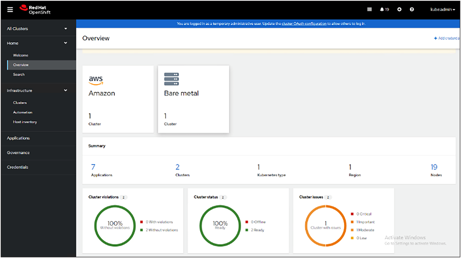
Red Hat Advanced Cluster Management for Kubernetes dashboard
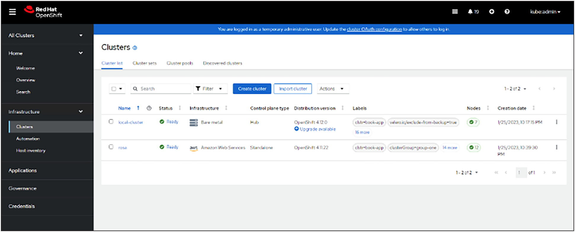
Red Hat Advanced Cluster Management for Kubernetes cluster overview
Running on Red Hat OpenShift, Red Hat Advanced Cluster Management for Kubernetes includes capabilities that unify multicluster management, provide Policy-based governance, and extend application lifecycle management.
Unified multicluster management
● Centrally create, update, and delete Kubernetes clusters across multiple private and public clouds.
● Search, find, and modify any Kubernetes resource across the entire domain.
● Quickly troubleshoot and resolve issues across your federated domain.
● When creating or updating clusters, automate tasks such as configuring cloud defined storage, static IP addresses, updating network components (such as firewalls or load balancers), and more with the integration of Red Hat Ansible Automation Platform.
Policy-based governance, risk, and compliance
● Centrally set and enforce policies for security, applications, and infrastructure.
● Quickly visualize detailed auditing on configuration of applications and clusters.
● Get immediate visibility into your compliance posture based on your defined standards.
● Automate remediation of policy violations and gather audit information about the clusters for analysis with the integration of Red Hat Ansible Automation Platform.
Advanced application lifecycle management
● Define and deploy applications across-clusters based on policy.
● Quickly view service endpoints and pods associated with your application topology – with all the dependencies.
● Automatically deploy applications to specific clusters based on channel and subscription definitions.
● When deploying or updating applications, automate configurations such as networking, databases, and more with the integration of Red Hat Ansible Automation Platform.
Multicluster observability for health and optimization
● Get an overview of multicluster health and optimization using out of the box multicluster dashboards with the capability to store long term data.
● Easily sort, filter, and do a deep scan of individual clusters or of aggregated multiclusters.
● Get an aggregated view of cluster metrics.
● Troubleshoot faster using the Dynamic Search and Visual Web Terminal capabilities.
Multicluster networking with Red Hat Submariner
● Provide cross-cluster network infrastructure with Red Hat Submariner (Submariner) for direct and encrypted communication.
● Use DNS service discovery for Kubernetes clusters connected by Submariner in multicluster environments.
● Uniformly manage and observe microservices based applications’ network flow for behavioral insight, control, and troubleshooting.
Portworx Enterprise Kubernetes storage platform
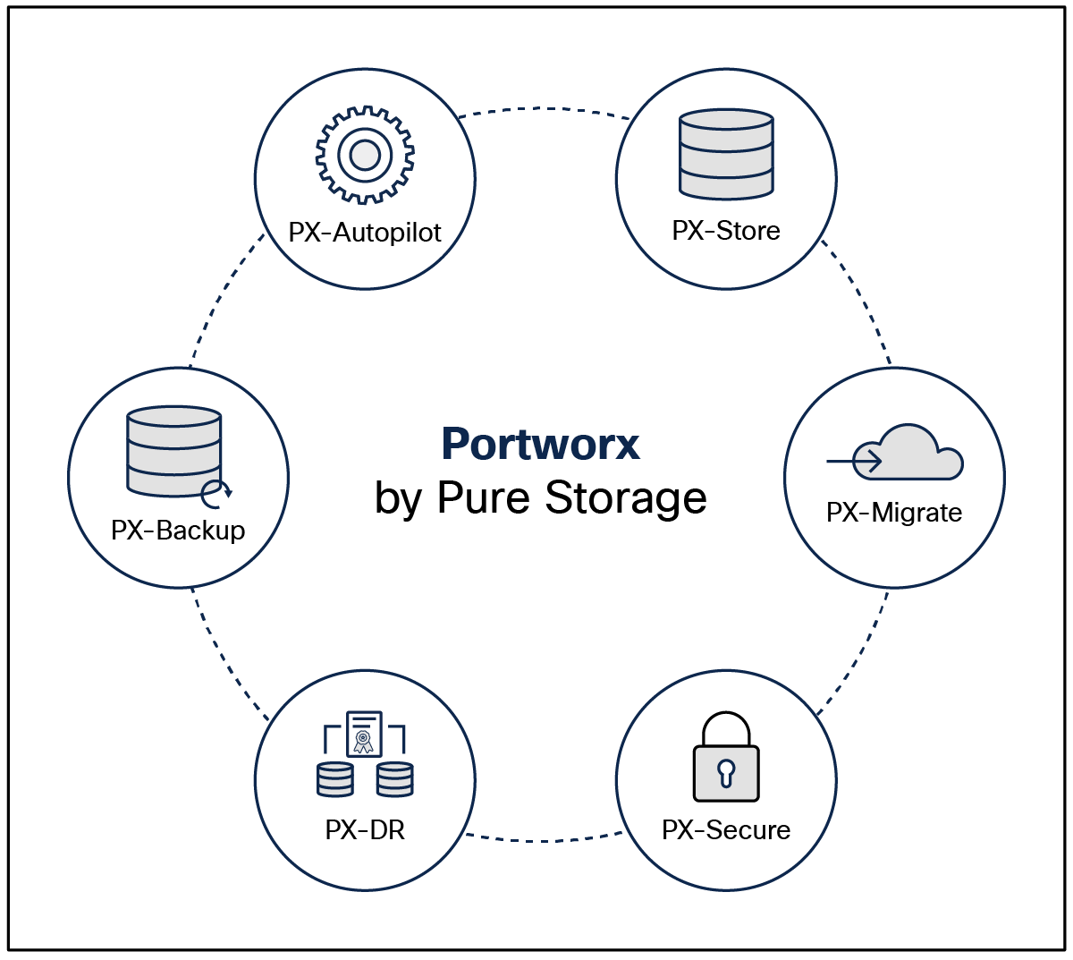
Portworx Enterprise is a multicloud ready software defined storage platform for running mission critical applications. Portworx (PX) is a fully integrated solution for persistent storage, disaster recovery, data security, cross cloud data migrations, and automated capacity management for applications.
Portworx provides container optimized storage for applications with no downtime, using such features as elastic scaling and a high availability solution across nodes/racks/availability zones. Portworx is designed to have consistent application performances by storage aware Class of Service (COS) and application aware I/O tuning.
Portworx Enterprise storage
Portworx secures the environment with encryption and access controls, provides cluster wide encryption with container or storage class‒based BYOK encryption. Portworx supports Role Based Access Control (RBAC) over both cluster operations and volume operations and integration with active directory and LDAP through OIDC.
For cloud native applications, Portworx allows local, application consistent/aware snapshots for multicontainer applications. Portworx Autopilot (PX-Autopilot) for Capacity Management has the ability to automatically resize individual container volumes or your entire collection of storage pools. Portworx rules based engine with customization capabilities can optimize applications based on performance requirements. PX-Autopilot can easily integrate with multiclouds such as Amazon Elastic Block Store, Google Persistent Disk, and Azure Blob Storage.
Portworx Backup (PX-Backup) can capture entire applications, including data, application configurations, and Kubernetes objects/metadata, and move them to any backup location at the click of a button, and its point and click recovery for any Kubernetes application makes it easy for developers. Portworx Disaster Recovery (PX-DR) has the ability to set DR policies at the container granular level and set multisite synchronous and asynchronous replication for a near zero RPO DR across a metro area.
This solution is for use cases and features that help administrators deploy and operate a robust Kubernetes stack for their developers.
Portworx solution overview
Key highlights of Pure Storage FlashArray//XL series:
● Increased capacity and performance: FlashArray//XL is designed for today’s higher powered multicore CPUs, allowing FlashArray//XL to increase performance over our FlashArray//X models. It provides more space for fans and airflow, which improves cooling efficiency, and for wider controllers, which enable performance to scale today and well into future generations of FlashArray//XL. With greater storage density, FlashArray//XL supports up to 40 DirectFlash modules in the main chassis.
● Increased connectivity, greater reliability, and improved redundancy: FlashArray//XL doubles the host I/O ports compared to FlashArray//X, for up to 36 ports per controller, and the //XL model provides more expansion slots for configuration flexibility. It doubles the bandwidth for each slot, including full bandwidth for mixed protocols. FlashArray//XL offers multiple 100GbE RDMA over Converged Ethernet (RoCE) links that are very robust to hot plug and provide faster controller failover speed.
● DirectFlash modules with distributed NVRAM: DirectFlash modules include onboard distributed non volatile random access memory (DFMD). With DFMD, NVRAM capacity, NVRAM write bandwidth, and array capacity, you can scale with the number of DFMDs, lifting the limit on write throughput.
● DirectCompress Accelerator: Included with every FlashArray//XL shipment, the DirectCompress Accelerator (DCA) increases compression efficiency by offloading inline compression to a dedicated PCIe card. It ensures maximum compression rates, even when the system is under a heavy load, and stretches capacity to reduce overall storage costs and to extend the value of your FlashArray//XL.
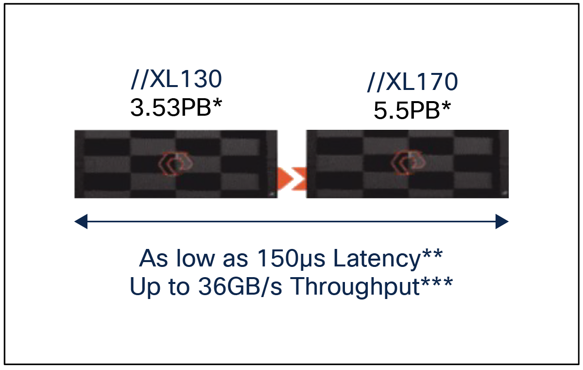
Pure Storage FlashArray//XL series
Table 1. FlashArray technical specifications
|
|
Capacity |
Physical |
| //XL170 |
Up to 5.5PB / 5.13PiB effective capacity* |
5-11U; 1850-2355W(nominal-peak) |
| Up to 1.4PB / 1.31PiB raw capacity** |
167lbs (75.7kg) fully loaded;8.72” x 18.94” x 29.72”** |
|
| //XL130 |
Up to 3.53PB / 3.3PiB effective capacity |
5-11U; 1550-2000 watts(nominal-peak) |
| Up to 968TB / 880TiB raw capacity |
167lbs (75.7kg) fully loaded; 8.72” x 18.94” x 29.72 |
|
| DirectFlash Shelf |
Up to 1.9PB effective capacity |
Up to 512TB / 448.2TiB raw capacity |
| 3U; 460-500 watts (nominal–peak) |
87.7lbs (39.8kg) fully loaded; 5.12” x 18.94” x 29.72” |
Table 2. FlashArray Connectivity
| Connectivity |
|
| Onboard Ports
● 2 x 1Gb (RJ45)
|
I/O Expansion Cards (6slots/controller)
●
2-port 10/25 Gb Ethernet, NVMe/TCP, NVMe/RoCE
●
2-port 40/100Gb Ethernet, NVMe/TCP, NVMe/RoCE
● 2-port 16/32/64†Gb FCP, NVMe/FC
● 4-port 16/32/64 Gb FCP, NVMe/FC
|
| Management Ports
● 1 x RJ45 Serial
● 1 x VGA
● 4 x USB 3.0
|
Advantages of using FlashArray as backend storage for Portworx Enterprise Storage Platform
Pure Storage FlashArray provides all flash storage backed by an enterprise class array with six nines reliability, data at rest encryption, and industry leading data reduction technology. Although Portworx supports any storage type, including Direct Attached Storage (DAS) and array based storage, using Portworx replicas to ensure data availability for application pods across nodes, then having all replicas provisioned from the same underlying FlashArray, will multiply your standard data reduction rate, for the application data, by the number of replicas for the persistent volume.
Portworx combined with Pure Storage FlashArray can be used as a cloud storage provider. This allows administrators to store data on-premises with FlashArray while benefiting from Portworx cloud drive features, automatically provisioning block volumes, expanding a cluster by adding new drives or expanding existing ones and support for PX-Backup and Autopilot. Pure Storage FlashArray with Portworx on Kubernetes can attach FlashArray as a direct access volume. Used in this way, Portworx directly provisions FlashArray volumes, maps them to a user PVC, and mounts them to pods. FlashArray Direct Access volumes support CSI operations such as filesystem operations. Snapshots, and QoS.
Container ready infrastructure: Portworx on top of Pure Storage FlashArray benefits from Kubernetes native storage and data management. Operate, scale, and secure modern applications and databases on FlashArray and FlashBlade with just a few clicks.
Amazon Web Services (AWS) and Red Hat OpenShift Service on AWS
AWS provides a flexible application computing environment for deploying cloud native infrastructure and applications. Red Hat OpenShift can accelerate application development and delivery by providing a consistent experience for developers and operators across both on-premises and public clouds. One set of Kubernetes APIs and management tooling, updated on the same schedule, and supported by the same industry leading vendor, can be deployed across all of an enterprise’s cloud and on-premises environments.
AWS is globally available, enabling enterprises to extend their enterprise deployments to a variety of AWS regions as needed. Red Hat OCP cluster nodes can also be distributed across multiple AWS Availability Zones (AZ) to ensure cluster and application availability.
OCP is available as a managed service on AWS, Red Hat OpenShift Service on AWS (ROSA), and as a self managed application platform. This solution uses the self managed service and the openshift install command line installation method. The automated installation uses several AWS services such as Route 53, DHCP, load balancers, Virtual Private Cloud (VPC), and EC2 instances that are deployed or used as a part of the installation process. Transit Gateways (TGWs) attached to the VPC provide connectivity to on-premises resources and services, including Kubernetes clusters and application workloads.
A VPC in AWS provides an isolated virtual networking environment on a shared infrastructure where users can deploy resources to support application workloads. Enterprises can deploy VPCs in AWS and connect them directly to the on-premises data center to enable connectivity between applications, services, and resources in each environment. One mechanism for enabling this connectivity is to use a site to site VPN to establish an IPsec VPN tunnel between the two locations.
Red Hat OpenShift Service on AWS
Red Hat OpenShift Services on AWS (ROSA) is a fully managed application platform that is integrated with AWS and managed by a global team of expert SREs. ROSA enables enterprises to focus on delivering value through their applications and workloads. It is easy to extend an on-premises OpenShift environment into the public cloud with ROSA’s self service deployment and robust SLAs.
Infrastructure as Code with Red Hat Ansible
Red Hat Ansible is an open source tool for Infrastructure as Code (IaC). Ansible is also used for configuration management and application software deployment. Ansible is designed to be agentless, secure, and simple. Ansible, available in Red Hat’s Ansible Automation Platform, is part of a suite of tools supported by Red Hat. Ansible manages endpoints and infrastructure components in an inventory file, formatted in YAML or INI. The inventory file can be a static file populated by an administrator or dynamically updated. Passwords and other sensitive data can be encrypted using Ansible Vault. Ansible uses playbooks to orchestrate provisioning and configuration management. Playbooks are written in human readable YAML format that is easy to understand. Ansible playbooks are executed against a subset of components in the inventory file. From a control machine, Ansible uses Secure Shell (SSH) or Windows Remote Management to remotely configure and provision target devices in the inventory based on the playbook tasks.
Ansible is simple and powerful, allowing users to easily manage various physical devices within FlashStack including the configuration of Cisco UCS bare metal servers, Cisco Nexus switches, Pure FlashArray storage, and VMware vSphere. Using Ansible’s playbook based automation is easy and integrates into your current provisioning infrastructure. This solution offers Ansible Playbooks that are made available from a GitHub repository that customers can access to automate the FlashStack deployment.
This architecture covers hybrid and multicloud management with GitOps as shown in the following figure. At a high level this requires a management hub for GitOps and infrastructure that extends to one or more managed clusters running on-premises FlashStack Data center and/or public clouds. The automated infrastructure-as-code approach can manage the versioning of components and deploy according to the infrastructure-as-code configuration.
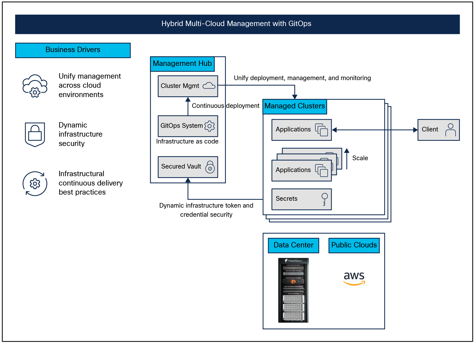
Overview of Multicloud validated patterns
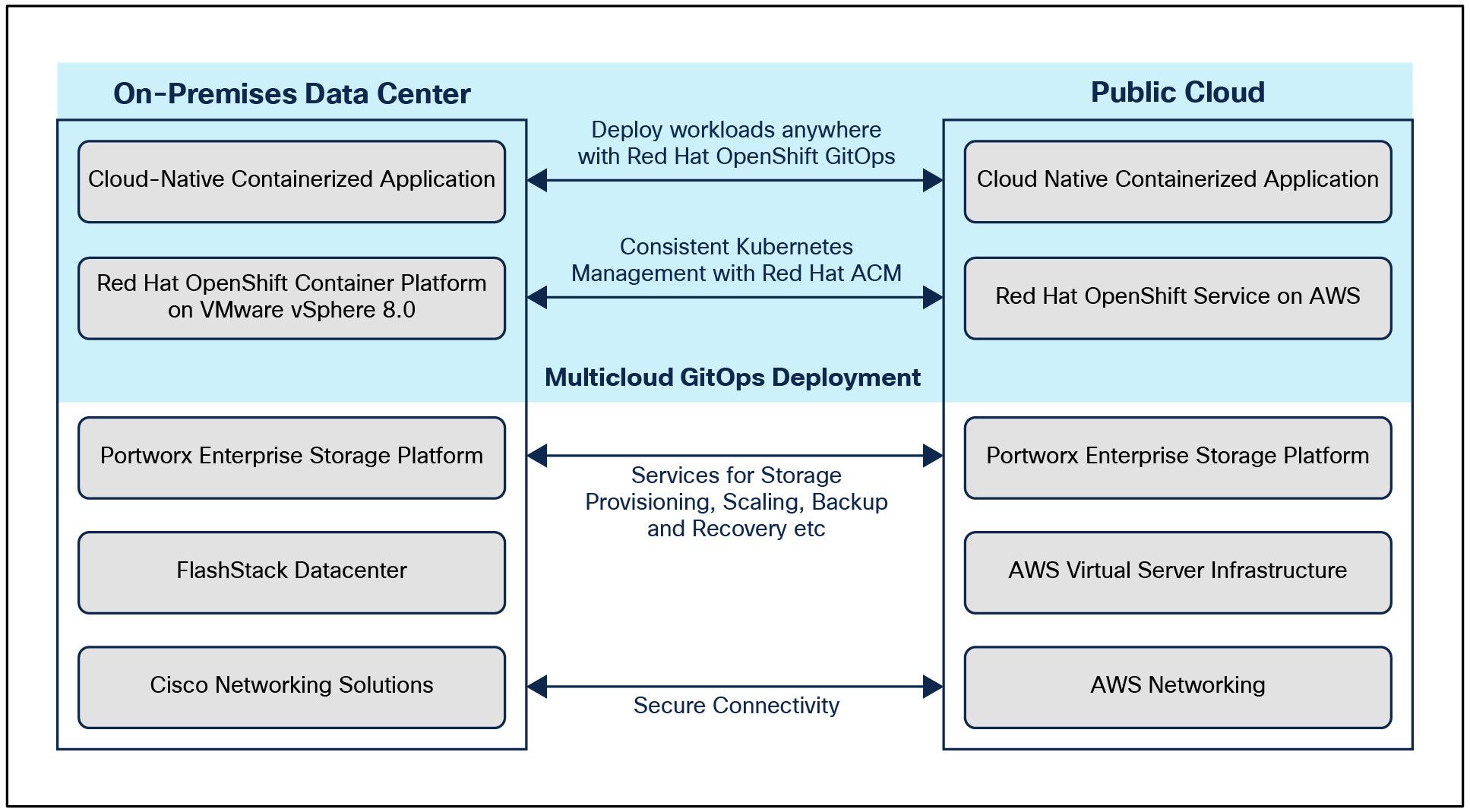
The hybrid-cloud infrastructure design in this solution consists of an on-premises data center, a public cloud infrastructure, and a secure network interconnecting the two environments. The Red Hat Validated Multicloud GitOps pattern is configured on the Red Hat OpenShift installed on the provisioned infrastructure.
Solution overview
FlashStack Virtual Server Infrastructure
The on-premises FlashStack Virtual Server Infrastructure (VSI) in the solution consists of:
● 6 x Cisco UCS X210c M6 Compute Nodes form a VMware vSphere 8.0 cluster. Control plane and worker nodes are running as virtual machines on the VMware vSphere 8.0 cluster. There can be more than one OCP clusters in a VMware vSphere 8.0 cluster.
● The cluster is deployed and managed from the cloud using Cisco Intersight.
● 2 x Cisco UCS X210c M6 Compute Nodes form a management cluster with a VMware vSphere 8.0 cluster hosting services and management components to support the application cluster. The cluster is deployed and managed from the cloud using Cisco Intersight. The services deployed include a VMware vCenter cluster managing applications and a DNS, DHCP, and OCP installer workstation. The management cluster can also host a management OCP cluster to run services and other components. For example, Red Hat’s Advanced Cluster Manager requires a seed OCP cluster to run on before it can be used for multicluster management.
Public virtual server infrastructure
The public virtual server Infrastructure in the solution consists of Red Hat OpenShift Service on AWS (ROSA), a fully managed, turnkey application platform.
Two redundant IPsec VPN connections provide secure connectivity between the cloud native environments. The VPN connections are between two Cisco Cloud Services 1000v series on-premises and transit gateway routers in the public cloud.
Red Hat OCP clusters provide a Kubernetes environment for cloud native applications and use cases. The clusters are deployed on FlashStack Data center and on AWS EC2 instances using Red Hat Hybrid-cloud and managed using Red Hat Advanced Cluster Management for Kubernetes.
Portworx Enterprise Kubernetes Storage Platform
Portworx Enterprise provides cloud native storage for applications running in the FlashStack Data center and on AWS. Portworx also provides various data services such as:
● PX-DR, which enables asynchronous disaster recovery for the solution.
● PX-Backup, which delivers enterprise grade application and data protection with fast recovery.
● PX Central, which provides a monitoring, metrics, and data management interface for Portworx Enterprise.
The figure below illustrates the end-to-end solution that was designed, built, and validated in Cisco internal labs.
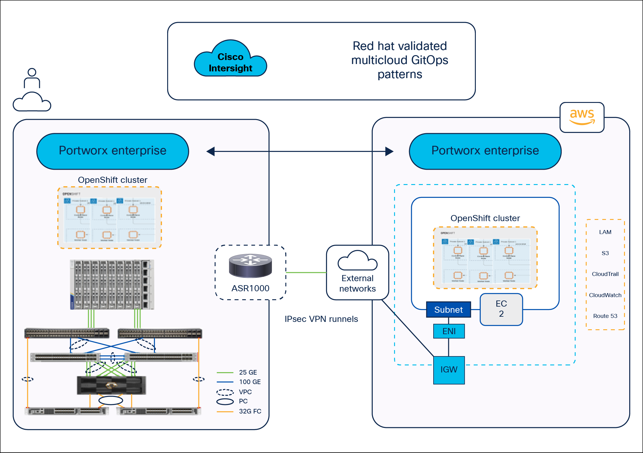
Solution topology
● Cisco UCS X-Series‒based FlashStack provides customers compute density, expandability, and all flash infrastructure in a single system. The Cisco UCS X210c M6 Compute Node allows customers to utilize the latest hardware innovations for running compute intensive workloads.
● Portworx provides data services across a hybrid-cloud. Portworx Container Storage Interface provides dynamic provisioning of persistent storage from FlashStack. Portworx is Red Hat‒certified and available for deployment on Red Hat’s operator hub.
● FlashStack and Cisco Intersight can quickly deliver a production ready continuous integration stack for virtualized and containerized workloads.
● Cisco Intersight simplifies operations by providing a comprehensive set of day 2 capabilities and tools.
● The Red Hat Validated Multicloud GitOps pattern is configured on the Red Hat OpenShift installed on the provisioned infrastructure.
On-premises infrastructure includes the FlashStack Data Center. This FlashStack design utilizes Cisco UCS X-Series servers connected through Cisco UCS fabric interconnects and managed with Cisco Intersight Infrastructure Manager (IMM).
FlashStack with Cisco UCS X-Series supports both IP based and Fibre Channel (FC)‒based storage access designs. For the IP based solution, an iSCSI configuration on Cisco UCS and Pure Storage FlashArray is utilized to set up storage access, including boot from SAN configurations for the compute nodes. For the Fibre Channel‒ based designs, Pure Storage FlashArray and Cisco UCS X-Series are connected using Cisco MDS 9132T switches, and storage access, including boot from SAN, is provided over the Fibre Channel network. The physical connectivity details for both IP and Fibre Channel designs are explained in the following sections.
IP-based storage access: iSCSI
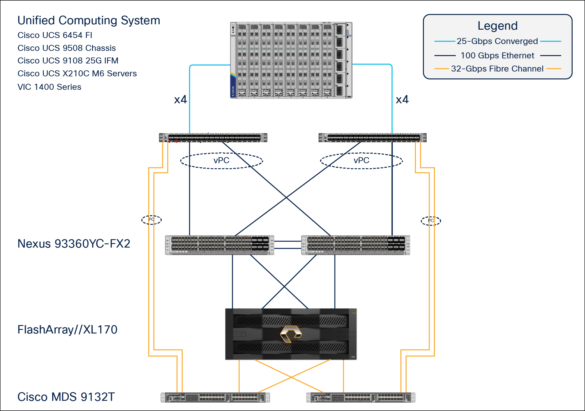
The physical topology for the IP based FlashStack is shown in Figure 31.
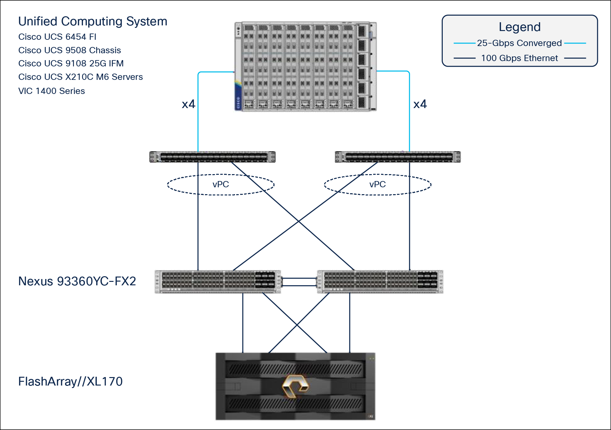
FlashStack ‒ physical topology for IP connectivity
To validate the IP based storage access in a FlashStack configuration, the components are set up as follows:
● Cisco UCS 6454 Fabric Interconnects provide the chassis and network connectivity.
● The Cisco UCS X9508 Chassis connects to fabric interconnects using Cisco UCSX 9108-25G Intelligent Fabric Modules (IFMs), where four 25 Gigabit Ethernet ports are used on each IFM to connect to the appropriate FI. If additional bandwidth is required, all eight 25G ports can be utilized.
● Cisco UCSX-210c M6 Compute Nodes contain fourth generation Cisco 14425 virtual interface cards.
● Cisco Nexus 93360YC-FX2 Switches in Cisco NX-OS mode provide the switching fabric.
● Cisco UCS 6454 Fabric Interconnect 100-Gigabit Ethernet uplink ports connect to Cisco Nexus 93360YC-FX2 Switches in a virtual Port Channel (vPC) configuration.
● The Pure Storage FlashArray//XL170 connects to the Cisco Nexus 93360YC-FX2 Switches using four 25-GE ports.
● VMware ESXi 8.0 is installed on Cisco UCSX-210c M6 Compute Nodes to validate the infrastructure.
● Red Hat OpenShift software is installed on a VMware vSphere 8.0 cluster.
Fibre Channel‒based storage access: Fibre Channel and FC-NVMe
The physical topology of the FlashStack for Fibre Channel connectivity is shown in Figure 32.
FlashStack ‒ physical topology for Fibre Channel connectivity
To validate the Fibre Channel‒based storage access in a FlashStack configuration, the components are set up as follows:
● Cisco UCS 6454 Fabric Interconnects provide the chassis and network connectivity.
● The Cisco UCS X9508 Chassis connects to fabric interconnects using Cisco UCSX 9108-25G Intelligent Fabric Modules (IFMs), where four 25 Gigabit Ethernet ports are used on each IFM to connect to the appropriate FI.
● Cisco UCS X210c M6 Compute Nodes contain fourth generation Cisco 14425 virtual interface cards.
● Cisco Nexus 93360YC-FX2 Switches in Cisco NX-OS mode provide the switching fabric.
● Cisco UCS 6454 Fabric Interconnect 100 Gigabit Ethernet uplink ports connect to Cisco Nexus 93360YC-FX2 Switches in a vPC configuration.
● Cisco UCS 6454 Fabric Interconnects are connected to the Cisco MDS 9132T switches using 32-Gbps Fibre Channel connections configured as a single port channel for SAN connectivity.
● The Pure Storage FlashArray//XL170 connects to the Cisco MDS 9132T switches using 32-Gbps Fibre Channel connections for SAN connectivity.
● VMware ESXi 8.0 is installed on Cisco UCS X210c M6 Compute Nodes to validate the infrastructure.
● Red Hat OpenShift software is installed on a VMware vSphere 8.0 cluster.
Table 3 lists the VLANs configured for setting up the FlashStack environment.
| VLAN ID |
Name |
Usage |
| 3 |
Native-VLAN |
Use VLAN 3 as native VLAN instead of default VLAN (1). |
| 1030 |
OOB-MGMT-VLAN |
Out-of-Band Management VLAN to connect the management ports for various devices. |
| 1031 |
IB-MGMT-VLAN |
In-Band Management VLAN utilized for all in-band management connectivity for example, ESXi hosts, VM management, and so on. |
| 1032 |
OCP-Data |
Data traffic VLAN from/to RH OCP Virtual Machines. |
| 3119 |
iSCSI-A* |
iSCSI-A path for supporting boot from san for both Cisco UCS B-Series and Cisco UCS C-Series servers. |
| 3219 |
iSCSI-B* |
iSCSI-B path for supporting boot from san for both Cisco UCS B-Series and Cisco UCS C-Series servers. |
| 3319 |
vMotion |
VMware vMotion traffic. |
| 3419 |
VM-Traffic |
VM data traffic VLAN. |
Some of the key highlights of VLAN usage are as follows:
● VLAN 1030 allows customers to manage and access out of band management interfaces of various devices and is brought into the infrastructure to allow CIMC access to the Cisco UCS servers; it is also available to infrastructure Virtual Machines (VMs). Interfaces in this VLAN are configured with MTU 1500.
● VLAN 1031 is used for in band management of VMs, hosts, and other infrastructure services. Interfaces in this VLAN are configured with MTU 1500.
● VLAN 1032 is the data traffic network for OCP cluster 1. Interfaces in this VLAN are configured with MTU 9000.
● A pair of iSCSI VLANs (3119 and 3219) is configured to provide access to boot LUNs for ESXi hosts and iSCSI datastores. These VLANs are not needed when configuring Fibre Channel connectivity. Interfaces in these VLANs are configured with MTU 9000.
In FlashStack deployments, each Cisco UCS server equipped with a Cisco® Virtual Interface Card (VIC) is configured for multiple Virtual Network Interfaces (vNICs), which appear to the OS as standards compliant PCIe endpoints. The end to end logical connectivity, including VLAN/VSAN usage between the server profile for an ESXi host and the storage configuration on Pure Storage FlashArray, is captured in the following sections.
Logical topology for IP based storage access
Figure 33 illustrates the end-to-end connectivity design for IP based storage access.
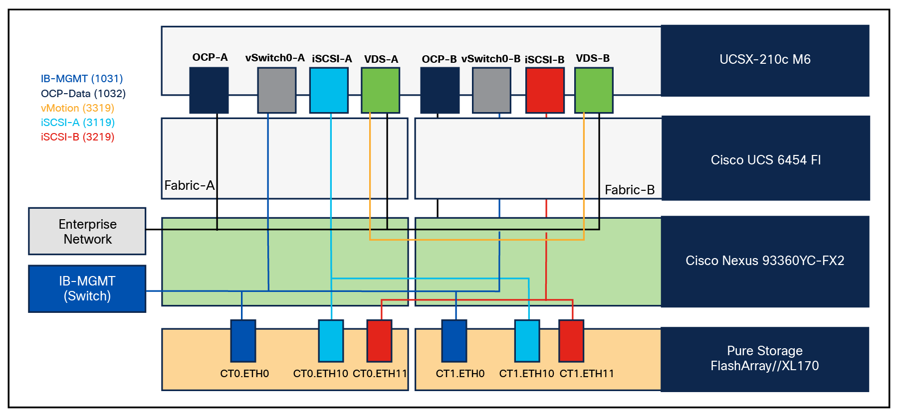
Logical end-to-end connectivity for iSCSI design
Each ESXi server profile supports:
● Managing the ESXi hosts using a common management segment
● Diskless SAN boot using iSCSI with persistent operating system installation for true stateless computing
● Eight vNICs where:
◦ Two redundant vNICs (vSwitch0-A and vSwitch0-B) carry management traffic. The maximum transmission unit (MTU) value for these vNICs is set to 1500.
◦ Two redundant vNICs (OCP-A and OCP-B) carry OCP data traffic. The MTU for the vNICs is set to Jum-bo MTU (9000).
◦ The vSphere Distributed Switch uses two redundant vNICs (VDS-A and VDS-B) to carry VMware vMotion traffic and customer application data traffic. The MTU for the vNICs is set to Jumbo MTU (9000).
◦ The iSCSI-A vSwitch uses one iSCSI-A vNIC to provide access to the iSCSI-A path. The MTU value for the vNIC is set to Jumbo MTU (9000).
◦ The iSCSI-B vSwitch uses one iSCSI-B vNIC to provide access to the iSCSI-B path. The MTU value for this vNIC is set to Jumbo MTU (9000).
● Each ESXi host (compute node) accesses datastores from Pure Storage FlashArray//XL170 using iSCSI to deploy virtual machines.
Logical topology for Fibre Channel‒based storage access
Figure 34 illustrates the end-to-end connectivity design for Fibre Channel‒based storage access.
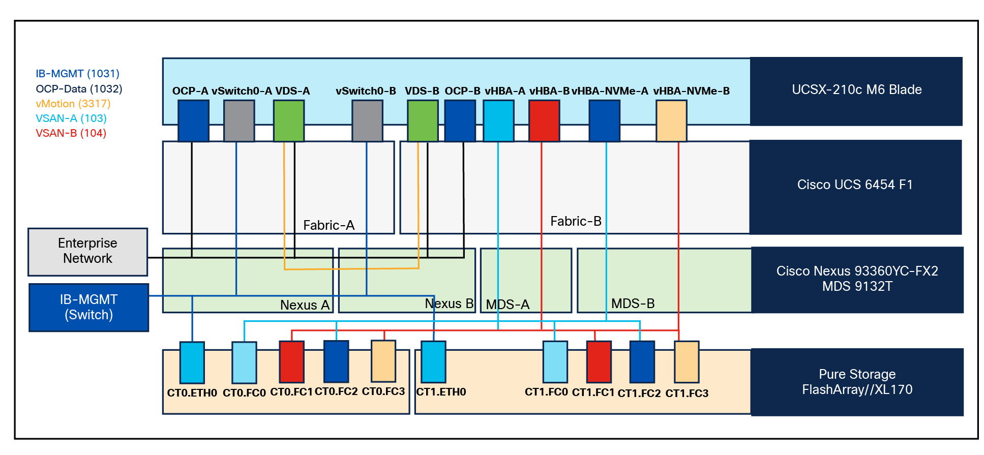
Logical end-to-end connectivity for Fibre Channel design
Each ESXi server profile supports:
● Managing the ESXi hosts using a common management segment
● Diskless SAN boot using Fibre Channel with persistent operating system installation for true stateless computing
● Six vNICs where:
◦ Two redundant vNICs (vSwitch0-A and vSwitch0-B) carry management traffic. The MTU value for these vNICs is set to 1500.
◦ Two redundant vNICs (OCP-A and OCP-B) carry OCP data traffic. The MTU for the vNICs is set to Jumbo MTU (9000).
◦ The vSphere Distributed Switch uses two redundant vNICs (VDS-A and VDS-B) to carry VMware vMotion traffic and customer application data traffic. The MTU for the vNICs is set to Jumbo MTU (9000).
● Four vHBAs where:
◦ One vHBA (vHBA-A) defined on Fabric A provides access to the SAN-A path (FC Initiator).
◦ One vHBA (vHBA-B) defined on Fabric B provides access to the SAN-B path (FC Initiator).
◦ One vHBA (vHBA-NVMe-A) defined on Fabric A provides access to the SAN-A path for NVMe over fabric traffic (FC-NVMe initiator).
◦ One vHBA (vHBA-NVMe-B) defined on Fabric B provides access to the SAN-B path for NVMe over fabric traffic (FC-NVMe initiator).
● Each ESXi host (compute node) accesses datastores from Pure Storage FlashArray using Fibre Channel to deploy virtual machines.
The Cisco UCS X9508 Chassis is equipped with Cisco UCSX 9108-25G Intelligent Fabric Modules (IFMs). The Cisco UCS X9508 Chassis connects to each Cisco UCS 6454 Fabric Interconnect using four 25GE ports, as shown in Figure 35. If you require more bandwidth, all eight ports on the IFMs can be connected to each FI.
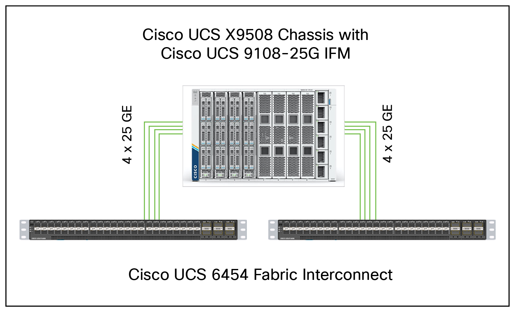
Cisco UCS X9508 Chassis connectivity to Cisco UCS fabric interconnects
Cisco Nexus Ethernet connectivity
The Cisco Nexus 93360YC-FX2 Switch configuration covers the core networking requirements for Layer-2 and Layer-3 communication. Some of the key Cisco NX-OS features implemented within the design are:
● Interface vlan: allows for VLAN IP interfaces to be configured within the switch as gateways.
● HSRP: allows for Hot Standby Routing Protocol configuration for high availability.
● LACP: allows for the utilization of Link Aggregation Control Protocol (802.3ad) by the port channels configured on the switch.
● Virtual Port Channel (vPC): presents the two Cisco Nexus switches as a single “logical” port channel to the connecting upstream or downstream device.
● Link Layer Discovery Protocol (LLDP): a vendor neutral device discovery protocol, allows the discovery of both Cisco devices and devices from other sources.
● NX-API: improves the accessibility of CLI by making it available outside of the switch by using HTTP/HTTPS. This feature helps with configuring the Cisco Nexus switch remotely using the automation framework.
● Uni Directional Link Detection (UDLD): enables unidirectional link detection for various interfaces.
Cisco UCS Fabric Interconnect 6454 Ethernet connectivity
Cisco UCS 6454 Fabric Interconnects (FIs) are connected to Cisco Nexus 93360YC-FX2 Switches using 100GE connections configured as virtual port channels. Each FI is connected to both Cisco Nexus switches using a 100G connection; additional links can easily be added to the port channel to increase the bandwidth as needed. Figure 36 illustrates the physical connectivity details.
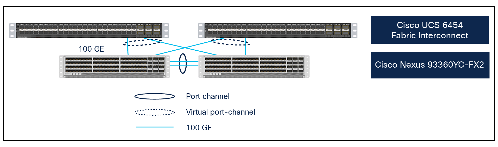
Cisco UCS 6454 FI Ethernet connectivity
Pure Storage FlashArray//XL170 Ethernet connectivity
Pure Storage FlashArray controllers are connected to Cisco Nexus 93360YC-FX2 Switches using redundant 100-GE. Figure 37. illustrates the physical connectivity details.
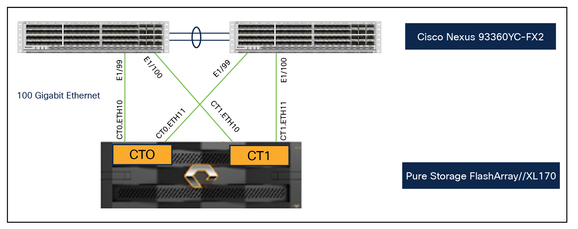
Pure Storage FlashArray//XL170 Ethernet connectivity
Cisco MDS SAN connectivity – Fibre Channel design
The Cisco MDS 9132T is the key design component bringing together the 32Gbps Fibre Channel (FC) capabilities to the FlashStack design. A redundant 32 Gbps Fibre Channel SAN configuration is deployed utilizing two Cisco MDS 9132Ts switches. Some of the key MDS features implemented within the design are:
● N port Identifier Virtualization (NPIV): provides a means to assign multiple FC IDs to a single N port.
● F-port channel trunk: allow for the fabric logins from the NPV switch to be virtualized over the port channel. This provides nondisruptive redundancy should individual member links fail.
● Smart Zoning: reduces the number of TCAM entries by identifying the initiators and targets in the environment.
Cisco UCS Fabric Interconnect 6454 SAN connectivity
For SAN connectivity, each Cisco UCS 6454 Fabric Interconnect is connected to a Cisco MDS 9132T SAN switch using 2 x 32G Fibre Channel port channel connections, as shown in Figure 38.
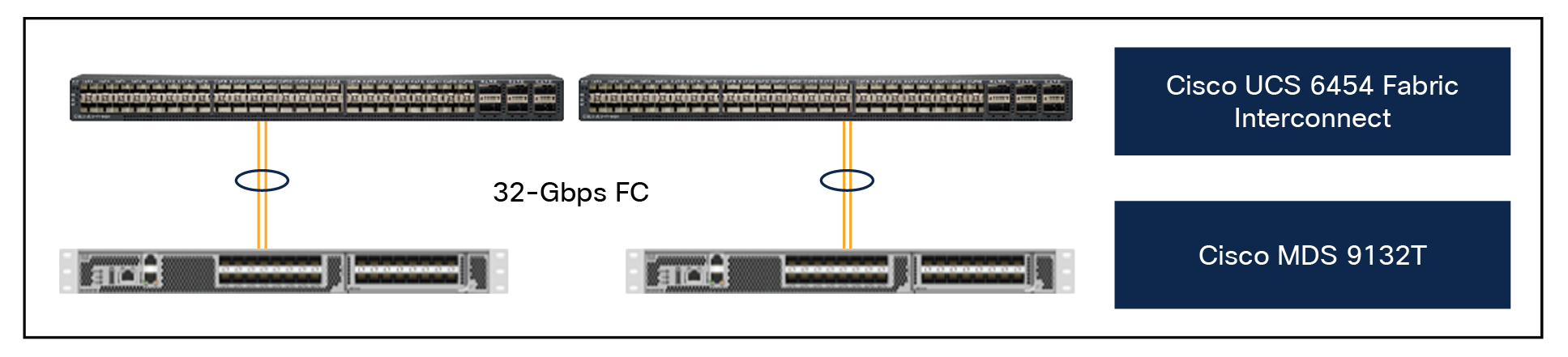
Cisco UCS 6454 Fabric Interconnect Fibre Channel (FC) connectivity
Pure Storage FlashArray//XL170 SAN connectivity
For SAN connectivity, each FlashArray controller is connected to both Cisco MDS 9132T SAN switches using 32G Fibre Channel connections, as shown in Figure 39.
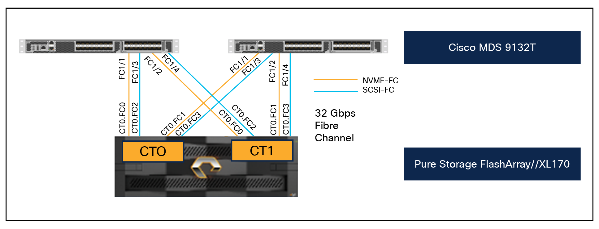
Pure Storage FlashArray Fibre Channel connectivity
Cisco UCS X-Series configuration ‒ Cisco Intersight Managed Mode
Cisco Intersight Managed Mode standardizes policy and operation management for Cisco UCS X-Series. The compute nodes in Cisco UCS X-Series are configured using server profiles defined in Cisco Intersight. These server profiles derive all the server characteristics from various policies and templates. At a high level, configuring Cisco UCS using Cisco Intersight Managed Mode consists of the steps shown in Figure 40.
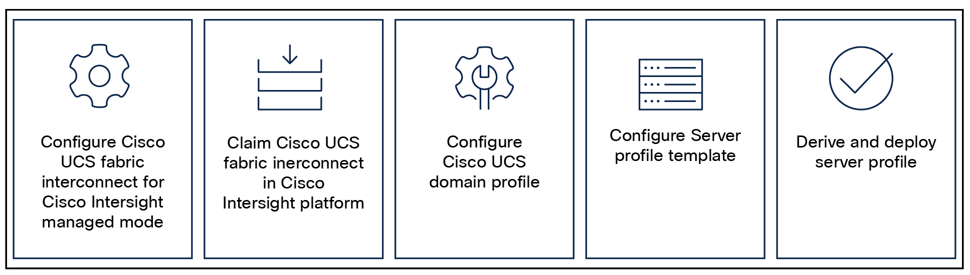
Configuration steps for Cisco Intersight Managed Mode
Set Up Cisco UCS fabric interconnect for Cisco Intersight Managed Mode
During the initial configuration, for the management mode, the configuration wizard enables customers to choose whether to manage the fabric interconnect through Cisco UCS Manager or the Cisco Intersight platform. Customers can switch the management mode for the fabric interconnects between Cisco Intersight and Cisco UCS Manager at any time; however, Cisco UCS fabric interconnects must be set up in Cisco Intersight Managed Mode (IMM) for configuring the Cisco UCS X-Series system. Figure 41 shows the dialog during initial configuration of Cisco UCS FIs for setting up IMM.
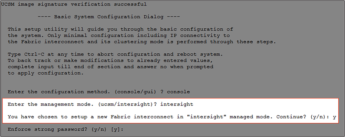
Fabric interconnect setup for Cisco Intersight Managed Mode
Claim a Cisco UCS fabric interconnect in the Cisco Intersight platform
After setting up the Cisco UCS 6454 Fabric Interconnect (FI) for Cisco Intersight Managed Mode, the FI can be claimed to a new or an existing Cisco Intersight account. When a Cisco UCS fabric interconnect is successfully added to Cisco Intersight, all future configuration steps are completed in the Cisco Intersight portal.
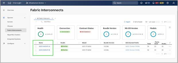
Cisco Intersight: adding fabric interconnects
You can verify whether a Cisco UCS fabric interconnect is in Cisco UCS Manager managed mode or Cisco Intersight Managed Mode by clicking on the fabric interconnect name and looking at the detailed information screen for the FI, as shown in Figure 43.
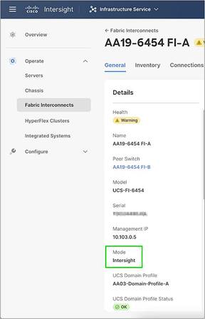
Cisco UCS fabric interconnect in Cisco Intersight Managed Mode
A Cisco UCS chassis profile configures and associates the chassis policy to a Cisco UCS chassis. The chassis profile feature is available in Cisco Intersight only if customers have installed the Cisco Intersight Essentials License. The chassis related policies can be attached to the profile either at the time of creation or later.
The chassis profile in a FlashStack is used to set the power policy for the chassis. By default, Cisco UCS X-Series power supplies are configured in GRID mode, but a power policy can be utilized to set the power supplies in nonredundant or N+1/N+2 redundant modes.
A Cisco UCS domain profile configures a fabric interconnect pair through reusable policies, allows configuration of the ports and port channels, and configures the VLANs and VSANs to be used in the network. It defines the characteristics of and configures the ports on the fabric interconnects. One Cisco UCS domain profile can be assigned to one fabric interconnect domain.
Some of the characteristics of the Cisco UCS domain profile in the FlashStack environment are:
● A single domain profile is created for the pair of Cisco UCS fabric interconnects.
● Unique port policies are defined for the two fabric interconnects.
● The VLAN configuration policy is common to the fabric interconnect pair because both fabric interconnects are configured for the same set of VLANs.
● The VSAN configuration policies (in the Fibre Channel connectivity option) are unique for the two fabric interconnects because the VSANs are unique.
● The Network Time Protocol (NTP), network connectivity, and system Quality-of-Service (QoS) policies are common to the fabric interconnect pair.
After the Cisco UCS domain profile has been successfully created and deployed, the policies (including the port policies) are pushed to Cisco UCS fabric interconnects. A Cisco UCS domain profile can easily be cloned to install additional Cisco UCS systems. When cloning the UCS domain profile, the new UCS domains utilize the existing policies for consistent deployment of additional Cisco UCS systems at scale.
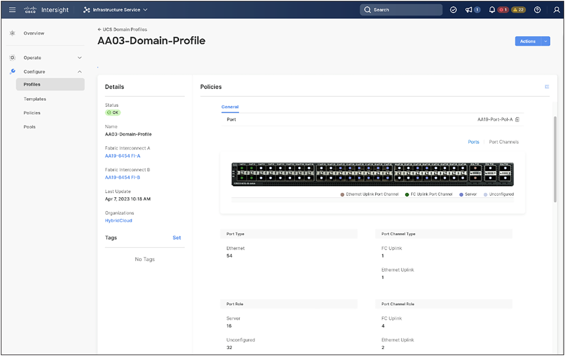
Cisco UCS domain profile
A Cisco UCS X9508 Chassis and Cisco UCS X210c M6 Compute Nodes are automatically discovered when the ports are successfully configured using the domain profile as shown in the following figures.
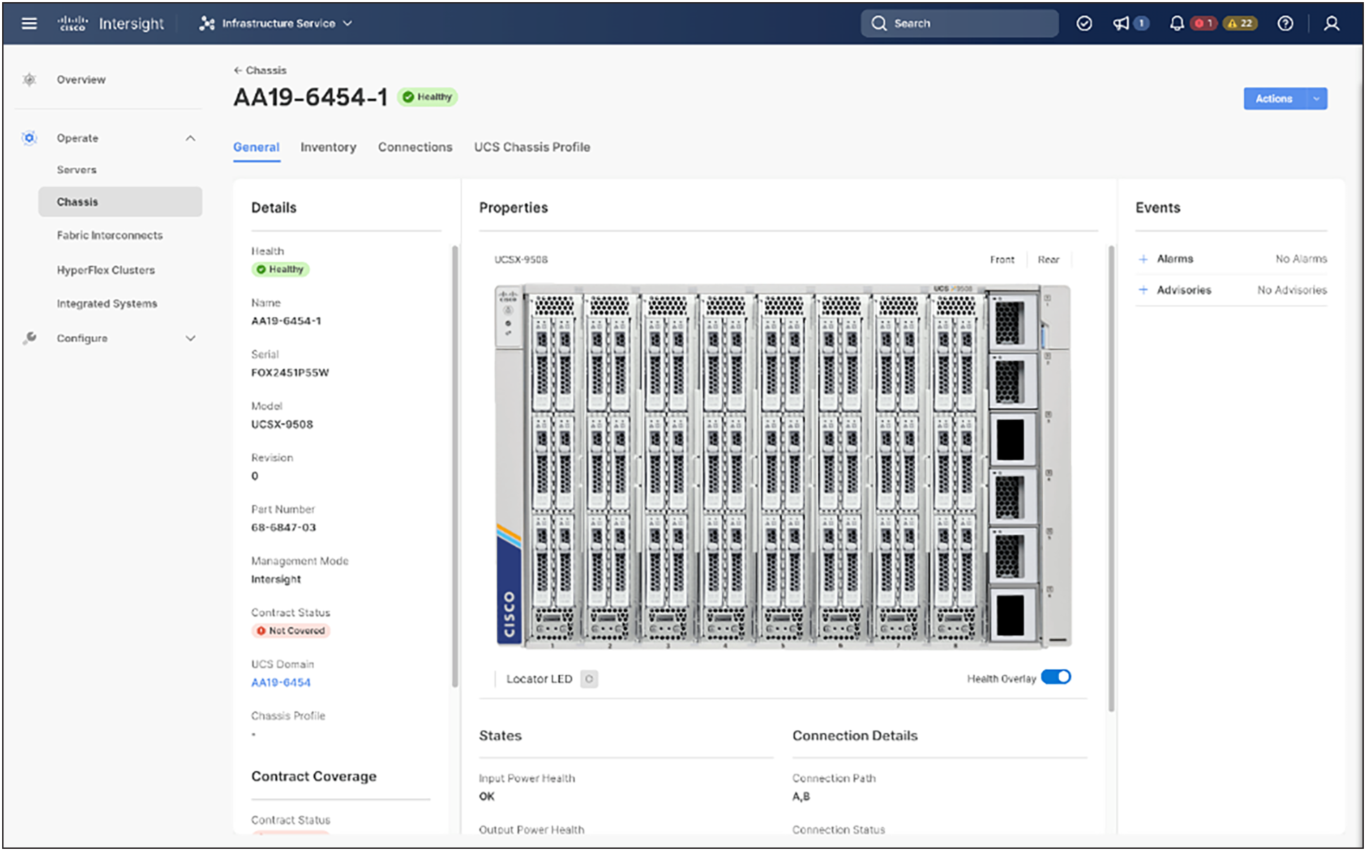
Cisco UCS X9508 Chassis front view
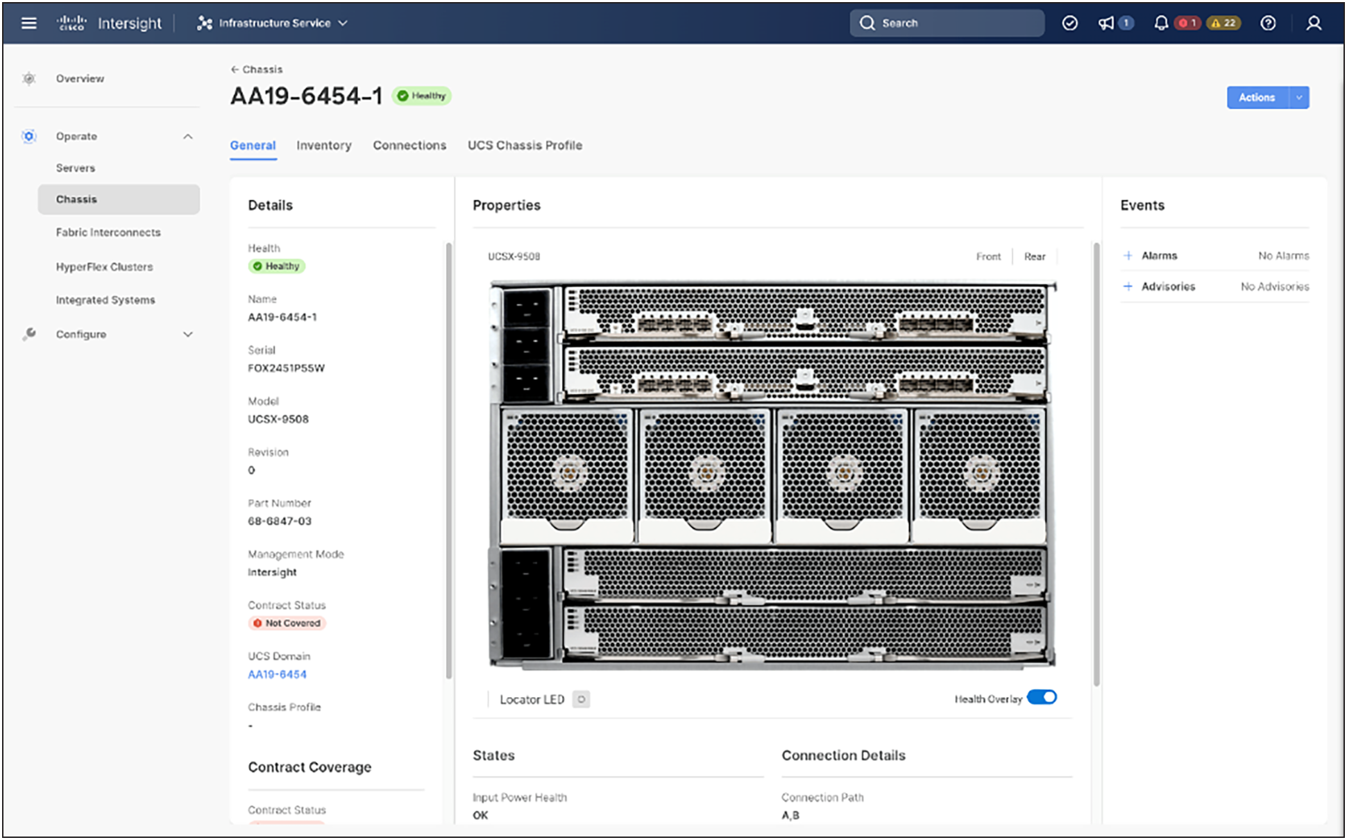
Cisco UCS X9508 Chassis rear view
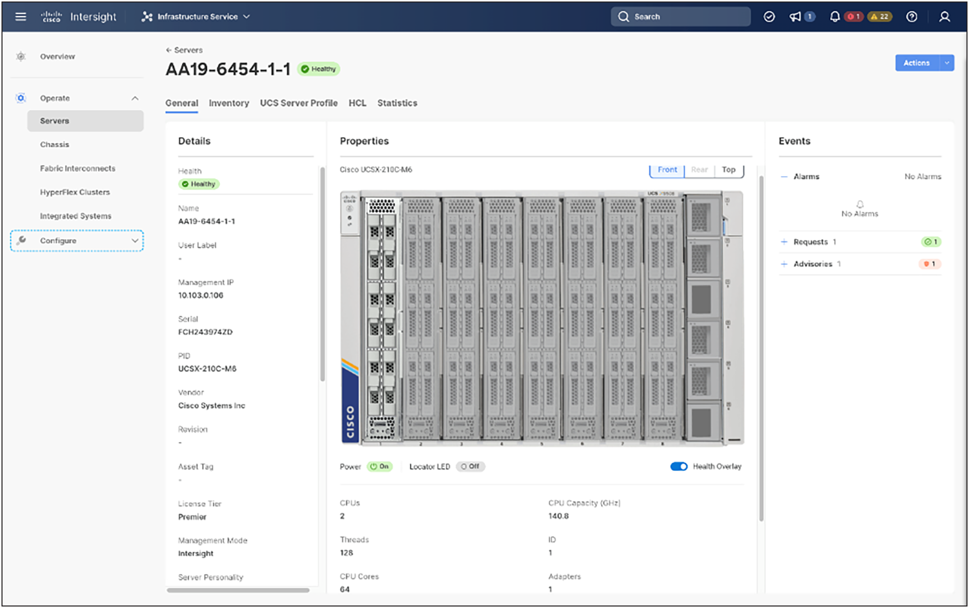
Cisco UCS X210c M6 Compute Nodes
A server profile template enables resource management by simplifying policy alignment and server configuration. A server profile template is created using the server profile template wizard. The server profile template wizard groups the server policies into the following four categories to provide a quick summary view of the policies that are attached to a profile:
● Compute policies: BIOS, boot order, and virtual media policies
● Network policies: Adapter configuration, LAN connectivity, and SAN connectivity policies
◦ The LAN connectivity policy requires you to create an Ethernet network policy, an Ethernet adapter policy, and an Ethernet QoS policy.
◦ The SAN connectivity policy requires you to create a Fibre Channel (FC) network policy, a Fibre Channel adapter policy, and a Fibre Channel QoS policy. A SAN connectivity policy is required only for the FC connectivity option.
● Storage policies configure local storage and are not used in FlashStack.
● Management policies: device connector, Intelligent Platform Management Interface (IPMI) over LAN, Lightweight Directory Access Protocol (LDAP), local user, network connectivity, Simple Mail Transfer Protocol (SMTP), Simple Network Management Protocol (SNMP), Secure Shell (SSH), Serial over LAN (SOL), syslog, and virtual Keyboard, Video, and Mouse (KVM) policies.
Some of the characteristics of the server profile template for FlashStack are the following:
● BIOS policy is created to specify various server parameters in accordance with FlashStack best practices.
● Boot order policy defines virtual media (KVM mapper DVD), all SAN paths for Pure Storage FlashArray (iSCSI or Fibre Channel interfaces), and UEFI Shell.
● IMC access policy defines the management IP address pool for KVM access.
● Local user policy is used to enable KVM-based user access.
● For the iSCSI boot from SAN configuration, a LAN connectivity policy is used to create eight virtual Network Interface Cards (vNICs) — two for management virtual switch (vSwitch0), two for OpenShift Container Platform data, two for application vSphere Distributed Switch (vDS), and one each for iSCSI A/B vSwitches. Various policies and pools are also created for the vNIC configuration.
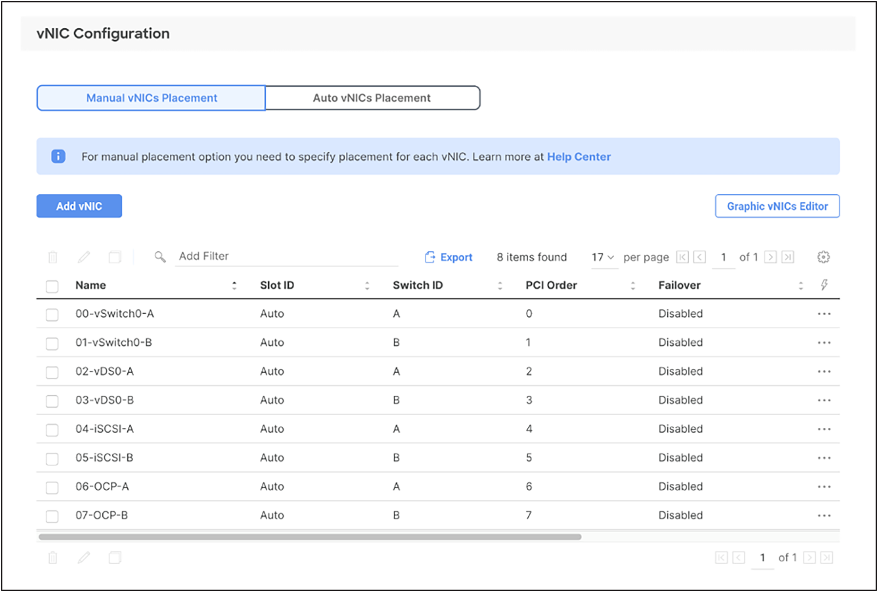
vNICs for iSCSI boot configuration
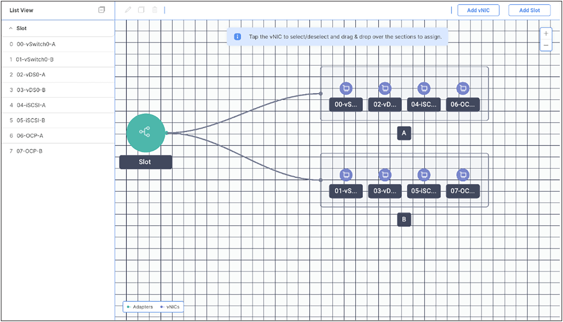
Graphical view of vNICs
● Fourth generation Cisco UCS VICs support up to 4096 receive and transmit ring sizes. Therefore, the Ethernet adapter policy can be configured accordingly while creating iSCSI vNICs for optimized performance.
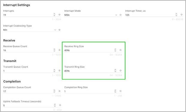
Graphical view of vNICs
● For the Fibre Channel boot from SAN configuration, a LAN connectivity policy is used to create six vNICs — two for management virtual switches (vSwitch0), two for OpenShift Container Platform data, and two for application VDSs — along with various policies and pools.
● For the Fibre Channel connectivity option, a SAN connectivity policy is used to create four virtual Host Bus Adapters (vHBAs) — along with various policies and pools. Two vHBAs (vHBA-A and vHBA-B) are of vHBA type “fc-initiator,” and two vHBAs (vHBA-NVMe-A and vHBA-NVMe-B) are of vHBA type “fc-nvme initiator.” The SAN connectivity policy is not required for iSCSI setup.
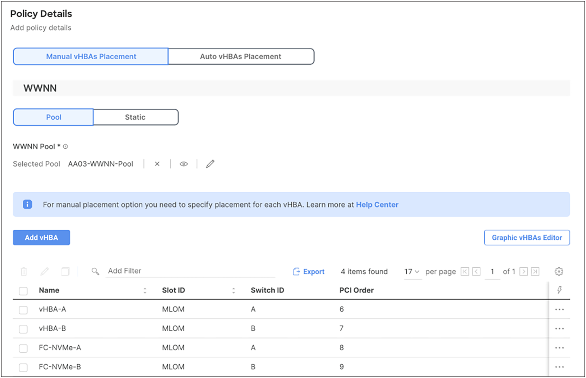
SAN connectivity policy
Figure 52 shows various policies associated with the server profile template.
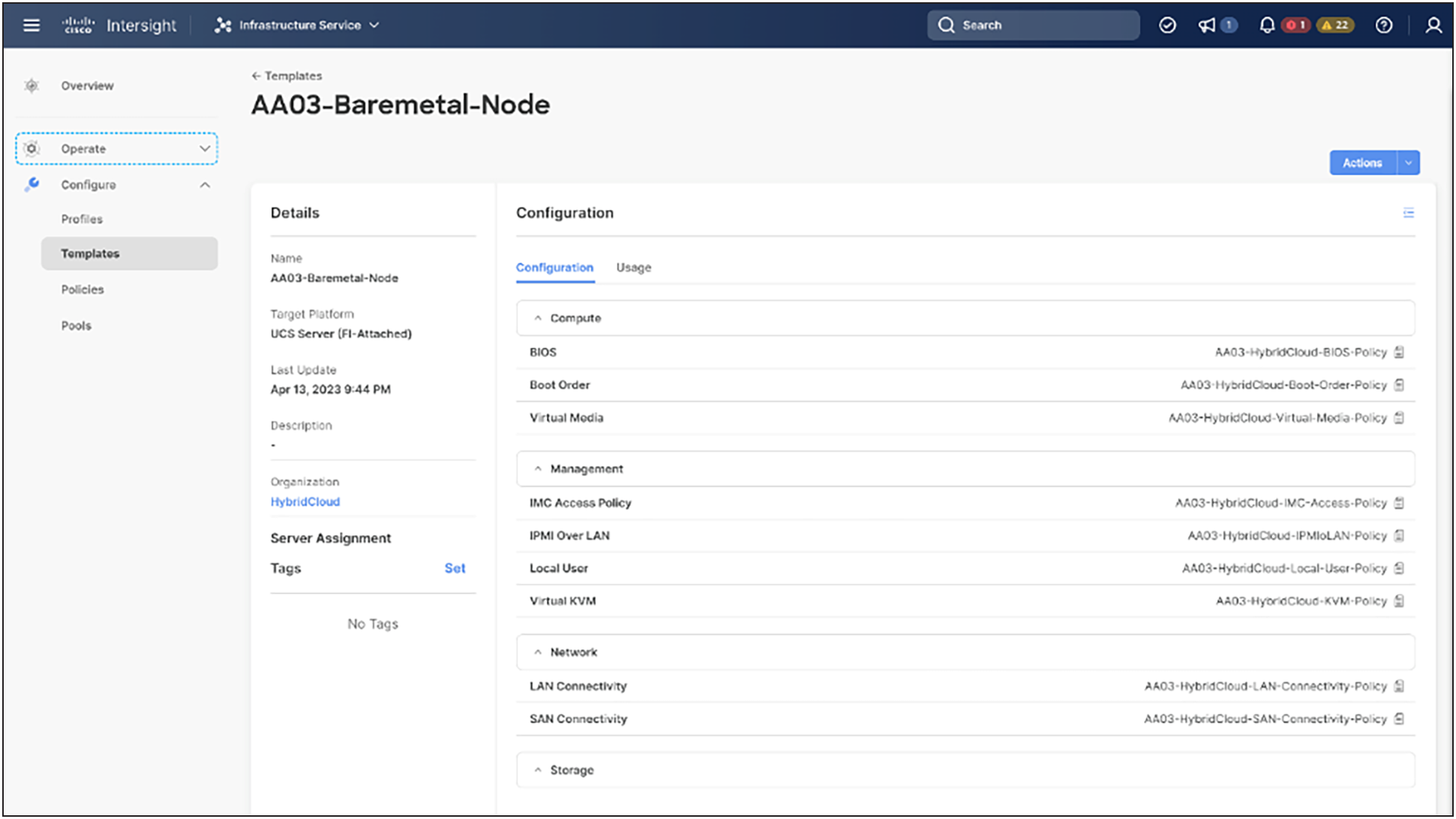
Server profile template for Fibre Channel boot from SAN
Multiple vNICs (and vHBAs) are created for the ESXi hosts using the Cisco Intersight server profile and are then assigned to specific virtual and distributed switches. The vNIC and (optional) vHBA distribution for the ESXi hosts is as follows:
● Two vNICs (one on each fabric) for vSwitch0 to support core services such as management traffic.
● Two vNICs (one on each fabric) for OCP Data vSwitch for OpenShift Container Platform data traffic.
● Two vNICs (one on each fabric) for vSphere Distributed Switch (vDS) to support customer data traffic and vMotion traffic.
● One vNIC each for Fabric A and Fabric B for iSCSI stateless boot. These vNICs are only required when an iSCSI boot from SAN configuration is desired.
● One vHBA each for Fabric A and Fabric B for Fibre Channel stateless boot. These vHBAs are only required when Fibre Channel connectivity is desired.
The following figures illustrate ESXi vNIC configurations in detail:
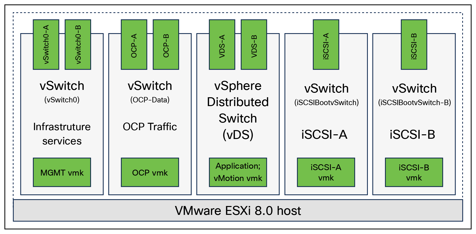
VMware vSphere – ESXi host networking for iSCSI boot from SAN
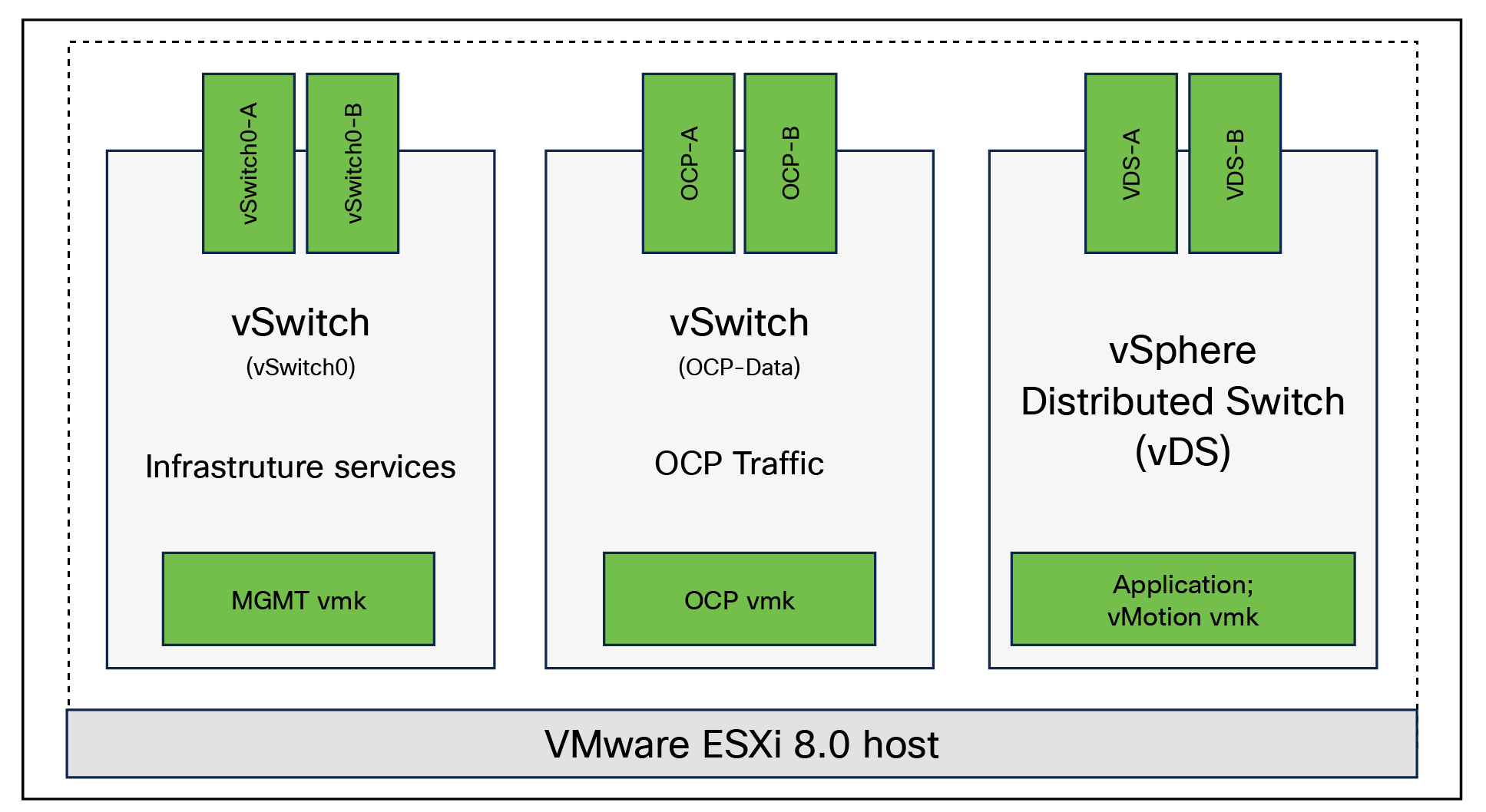
VMware vSphere – ESXi host networking for Fibre Channel foot from SAN
Pure Storage FlashArray – storage design
To set up Pure Storage FlashArray you must configure the following items:
● Volumes
◦ ESXi boot LUNs: these LUNs enable ESXi host boot from SAN functionality using iSCSI or Fibre Channel.
◦ The vSphere environment: vSphere uses the infrastructure datastore(s) to store the virtual machines.
● Hosts
◦ All FlashArray ESXi hosts are defined.
◦ Add every active initiator for a given ESXi host.
● Host groups
◦ All ESXi hosts in a VMware cluster are part of the host group.
◦ Host groups are used to mount VM infrastructure datastores in the VMware environment.
The volumes, interfaces, and VLAN/VSAN details are shown in the following figures for iSCSI and Fibre Channel connectivity, respectively.
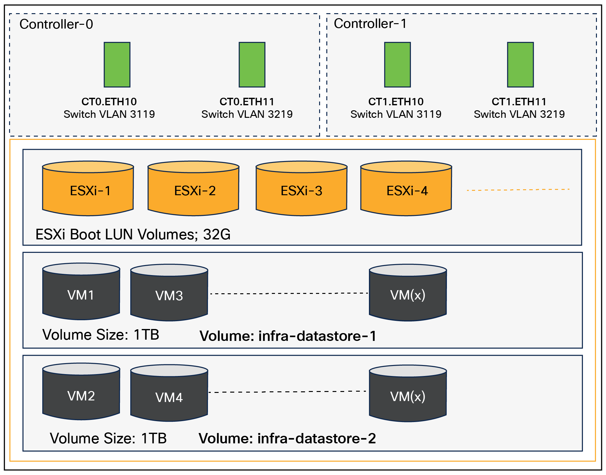
Pure Storage FlashArray volumes and interfaces – iSCSI configuration
Along with SCSI-FC, the solution also implements NVMe using the FC-NVMe protocol over a SAN built using Cisco MDS switches. NVMe initiators consisting of Cisco UCS X210C servers installed with Cisco VIC adapters can access Pure FlashArray NVMe targets over Fibre Channel.
Each port on the Pure Storage FlashArray can be configured as traditional SCSI-FC port or as an NVMe-FC port to support NVMe end-to-end through Fibre Channel from the host to the storage array. Note that a given Fibre Channel port is either going to be SCSI or NVMe, not on the FlashArray.
Two ports on each Pure Storage FlashArray controllers are configured as SCSI ports, and the other two are configured as NVMe ports in this design validation, as shown in Figure 56.
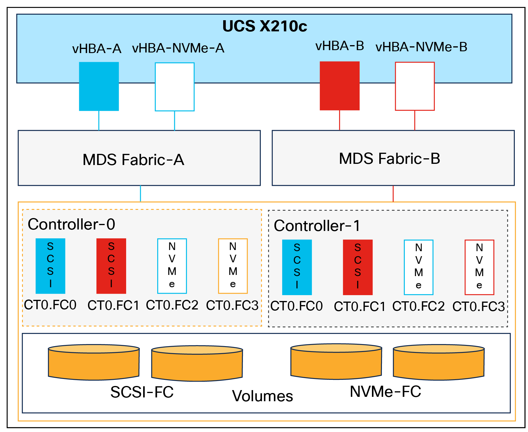
Pure Storage FlashArray volumes and interfaces – Fibre Channel configuration
Cisco UCS provides a unified fabric architecture that delivers flexibility, scalability, intelligence, and simplicity. This flexibility allows Cisco UCS to readily support new technologies, such as FC-NVMe, seamlessly. In a Cisco UCS service profile, both standard Fibre Channel and FC-NVMe vHBAs can be created.
Both Fibre Channel and FC-NVMe vHBAs can exist in a Cisco UCS service profile on a single server. In the lab validation for this document, four vHBAs (one FC-NVME initiator on each Fibre Channel fabric and one Fibre Channel initiator on each Fibre Channel fabric) were created in each service profile. Each vHBA, regardless of type, was automatically assigned a Worldwide Node Name (WWNN) and a Worldwide Port Name (WWPN). The Cisco UCS fabric interconnects were in Fibre Channel end host mode (NPV mode) and up linked through a SAN port channel to the Cisco MDS 9132T switches in NPV mode. Zoning in the Cisco MDS 9132T switches connected the vHBAs to storage targets for both FC-NVMe and Fibre Channel. Single initiator, multiple target zones were used for both FCP and FC-NVMe.
The ESXi automatically connects to Pure Storage FlashArray NVMe subsystem and discovers all shared NVMe storage devices that it can reach once the SAN zoning on MDS switches and configurations of host/host groups and volumes are completed on the FlashArray.
Pure Storage FlashArray considerations
Connectivity
● Each FlashArray controller should be connected to BOTH storage fabrics (A/B).
● Make sure to include I/O cards that support 25 GE are installed in the original FlashArray BOM.
● Pure Storage offers up to 32Gb Fibre Channel support on the FlashArray//X and 64Gb FC on the latest FlashArray//XL series arrays. Always make sure the correct number of HBAs and SFPs (with appropriate speed) are included in the original FlashArray BOM.
● For NVMe-FC, make sure to include the I/O controller interfaces with the service “NVMe-FC”.
Host groups and volumes
It is a best practice to map hosts to host groups and host groups to volumes in Pure Storage Purity. This ensures the volume is presented on the same LUN ID to all hosts and allows for simplified management of ESXi clusters across multiple nodes.
Size of the volume
Pure Storage Purity removes the complexities of aggregates and RAID groups. When managing storage, a volume should be created based on the size required, and Purity takes care of availability and performance through RAID-HD and Pure Storage DirectFlash software. Customers can create 1 10TB volume or 10 1TB volumes, and the performance and availability for these volumes will always be consistent. This feature allows customers to focus on recoverability, manageability, and administrative considerations of volumes instead of dwelling on availability or performance.
VMware vCenter deployment considerations
While hosting VMware vCenter on the same ESXi hosts that vCenter will manage is supported, it is a best practice to deploy vCenter on a separate management infrastructure. The ESXi hosts in this new FlashStack with Cisco UCS X-Series environment can also be added to an existing customer vCenter. The in band management VLAN will provide connectivity between vCenter and the ESXi hosts deployed in the new FlashStack environment.
Jumbo frames
An MTU of 9216 is configured at all network levels to allow jumbo frames as needed by the guest OS and application layer. The MTU value of 9000 is used on all the vSwitches and vSphere Distributed Switches (vDS) in the VMware environment.
Boot from SAN
When utilizing Cisco UCS server technology with shared storage, it is recommended to configure boot from SAN and to store the boot LUNs in remote storage. This enables architects and administrators to take full advantage of the stateless nature of Cisco UCS X-Series server profiles for hardware flexibility across the server hardware and for overall portability of server identities. Boot from SAN also removes the need to populate local server storage, thereby reducing cost and administrative overhead.
UEFI boot
This validation of FlashStack uses a Unified Extensible Firmware Interface (UEFI). UEFI is a specification that defines a software interface between an operating system and platform firmware.
NVMe over Fabrics (NVMe-oF) is an extension of the NVMe network protocol to Ethernet and Fibre Channel and delivers faster and more efficient connectivity between storage and servers, as well as a reduction in CPU utilization of application host servers. This validation of FlashStack supports NVMe over Fibre Channel (NVMe/FC) to provide the high performance and low latency benefits of NVMe across fabrics. In this solution, NVMe initiators consisting of Cisco UCS X210c Compute Nodes access Pure Storage FlashArray NVMe targets over Fibre Channel.
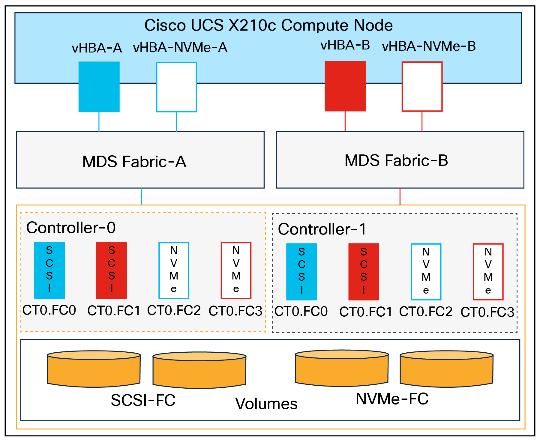
End-to-end NVMe over Fibre Channel connectivity
Each port on the Pure Storage FlashArray can be configured as a traditional SCSI-FC port or as an NVMe-FC port to support NVMe end-to-end through Fibre Channel from the host to the storage array. Two ports on each Pure Storage FlashArray controller are configured as SCSI ports, and two ports are configured as NVMe ports, as shown in Figure 57.
Note: A given Fibre Channel port on Pure Storage FlashArray can be configured as either an FC-SCSI or FC-NVMe port.
In a Cisco UCS server profile, both standard Fibre Channel and FC-NVMe vHBAs can be created. A default Fibre Channel adapter policy named fc-nvme-initiator is preconfigured in Cisco Intersight. This policy contains recommended adapter settings for FC-NVMe. Both Fibre Channel and FC-NVMe vHBAs can exist in a Cisco UCS server profile on a single server.
To support NVMe over Fabric, four vHBAs, two FC-NVME initiators and two Fibre Channel initiators (one on each Fibre Channel fabric), are created for each server profile. Cisco MDS 9132T switches are configured with appropriate zoning to connect the FC-NVMe and Fibre Channel vHBAs to appropriate storage targets. Single initiator, multiple target zones are used for both FCP and FC-NVMe. VMware ESXi automatically connects to the Pure Storage FlashArray NVMe subsystem and discovers all shared NVMe storage devices that it can reach once the SAN zoning on MDS switches and configurations of host/host groups and volumes are completed on the FlashArray.
Cisco Intersight integration with FlashStack
Cisco Intersight enhances the ability to provide complete visibility, orchestration, and optimization across all elements of FlashStack Data Center. This empowers customers to easily manage, make intelligent deployment decisions, optimize cost and performance, and maintain supported configurations for their infrastructure.
Cisco Intersight works with Pure Storage FlashArray, VMware vCenter using third party device connectors. Since third party infrastructure does not contain any built in Intersight device connector, Cisco Intersight Assist virtual appliance enables Cisco Intersight to communicate with these non Cisco devices. Also, Physical, and logical inventories of Ethernet and Storage area networks are available within Intersight.
Note: A single Cisco Intersight Assist virtual appliance can support both Pure Storage FlashArray and VMware vCenter.
Cisco Intersight integration with VMware vCenter, Pure Storage FlashArrays, and Cisco Nexus and Cisco MDS switches enables customers to perform the following tasks right from the Intersight dashboard:
● Monitor the virtualization of storage and network environments.
● Add various dashboard widgets to obtain useful at a glance information.
● Perform common virtual machine tasks such as power on/off, remote console, and so on.
● Orchestration of virtual, storage, and network environments to perform common configuration tasks.
● Extend optimization capabilities for the entire FlashStack Data Center
The following sections explain the details of these operations. Since Cisco Intersight is a SaaS platform, up dated monitoring and orchestration capabilities are constantly being added and delivered seamlessly from the cloud.
Note: The monitoring capabilities and orchestration tasks and workflows listed below provide an in time snapshot for your reference. For the most up to date list of capabilities and features, you should use the help and search capabilities in Cisco Intersight.
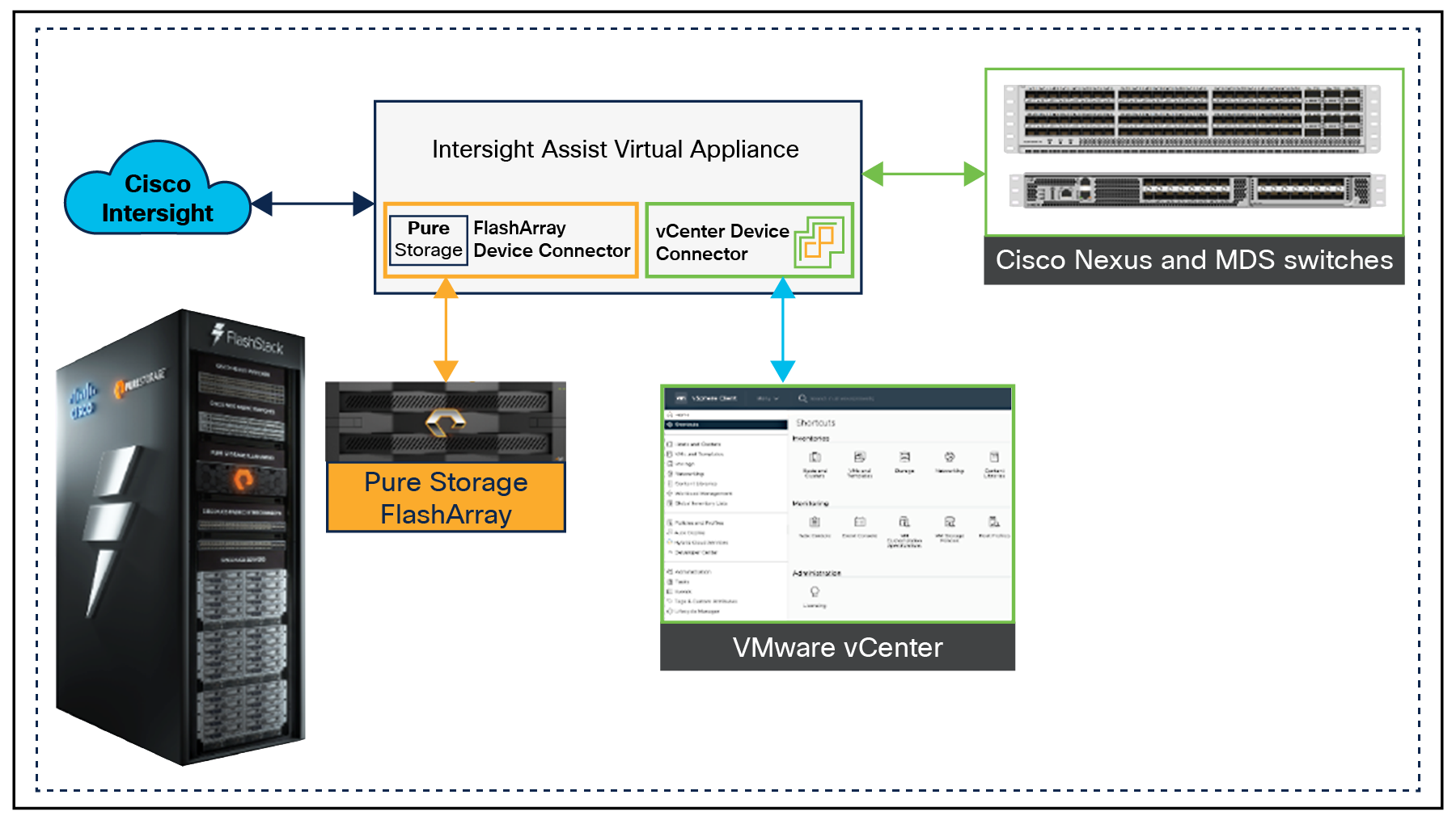
Managing Pure Storage FlashArray and VMware vCenter through Cisco Intersight using Intersight Assist
Integrate Cisco Intersight with Pure Storage FlashArray
To integrate Pure Storage FlashArray with the Cisco Intersight platform, you must deploy a Cisco Intersight Assist virtual appliance and claim Pure Storage FlashArray as a target in the Cisco Intersight application.
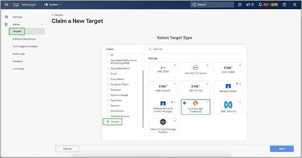
Claiming Pure Storage FlashArray as a target in Cisco Intersight
After successfully claiming Pure Storage FlashArray as a target, you can view storage level information in Cisco Intersight.
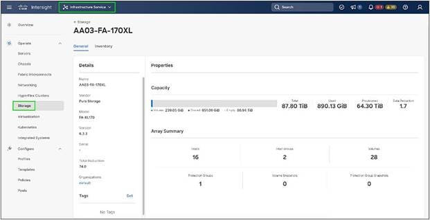
Pure Storage FlashArray information in Cisco Intersight
Cisco Intersight Cloud Orchestrator provides various workflows that can be used to automate storage provisioning. Some of the storage workflows available for Pure Storage FlashArray are listed in Figure 61.
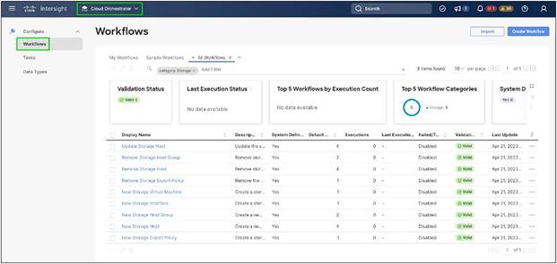
Storage workflows in Cisco Intersight Cloud Orchestrator
Integrate Cisco Intersight with VMware vCenter
To integrate VMware vCenter with Cisco Intersight, VMware vCenter can be claimed as a target using the Cisco Intersight Assist virtual appliance, as shown in Figure 62.
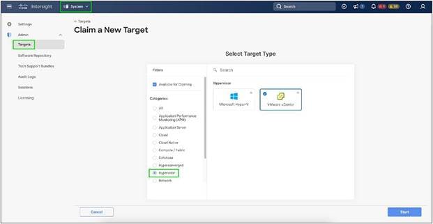
Claiming VMware vCenter target
After successfully claiming the VMware vCenter as a target, you can view hypervisor level information in Cisco Intersight, including hosts, VMs, clusters, datastores, and so on.
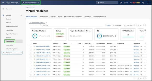
VMware vCenter information in Cisco Intersight
VMware vCenter integration with Cisco Intersight allows you to directly interact with the Virtual Machines (VMs) from the Cisco Intersight dashboard. In addition to obtaining in depth information about a VM, including the operating system, CPU, memory, host name, and IP addresses assigned to the virtual machines, you can use Intersight to perform various actions.
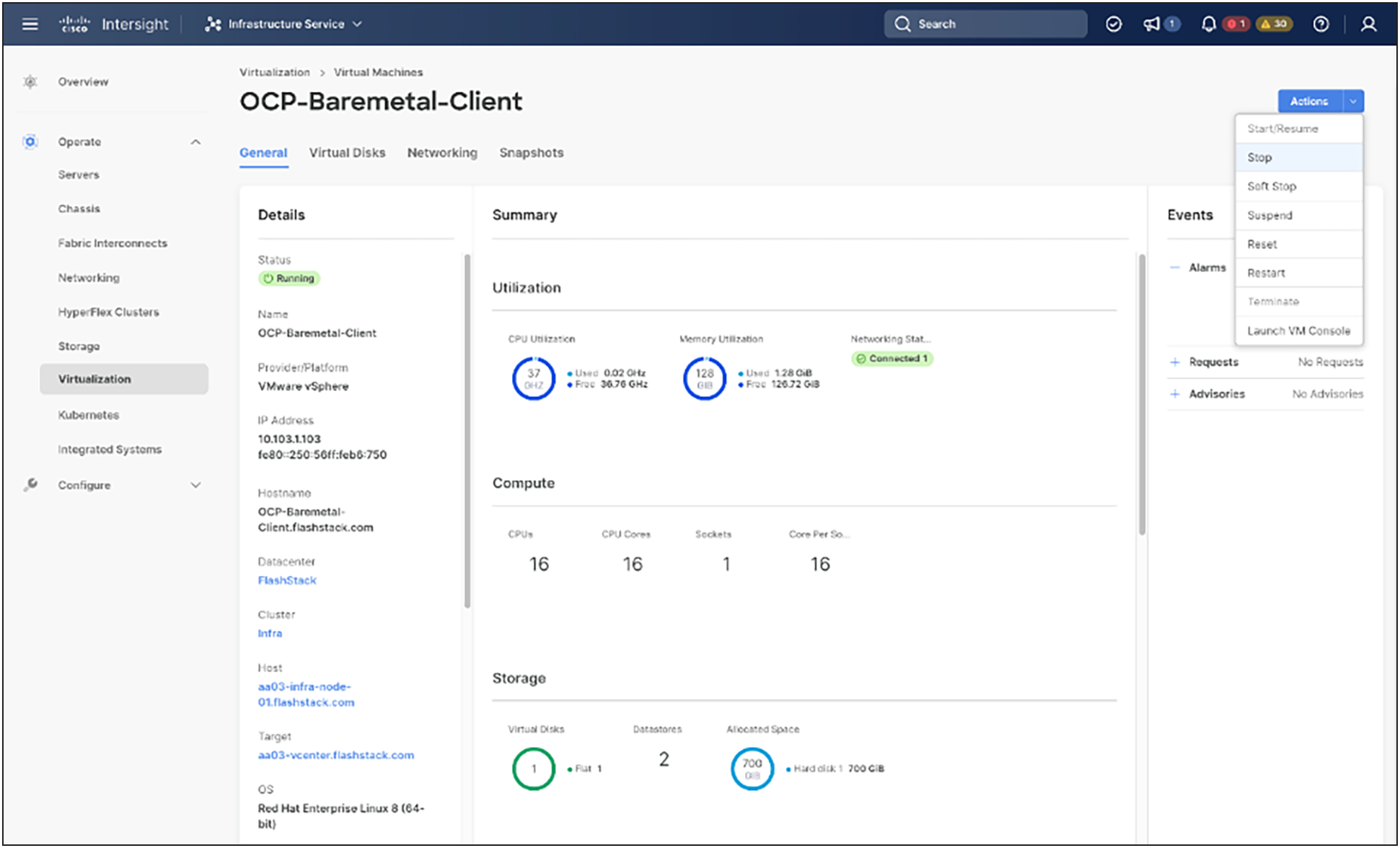
Virtual machine actions in Cisco Intersight
Cisco Intersight Cloud Orchestrator provides various workflows that can be used for VM and hypervisor provisioning.
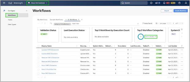
Virtualization workflows in Cisco Intersight Cloud Orchestrator
Integrate Cisco Intersight with Cisco Nexus and Cisco MDS switches
To integrate Cisco Nexus and Cisco MDS switches with Cisco Intersight, Nexus, and MDS switches can be claimed as targets using the Cisco Intersight Assist virtual appliance deployed earlier.
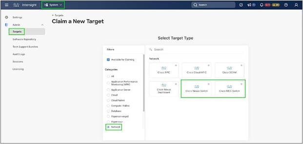
Claiming Cisco Nexus and Cisco MDS targets
After successfully claiming the Cisco Nexus and Cisco MDS switches as targets, you can view their Ethernet and SAN details, including physical and logical inventories, in Cisco Intersight.
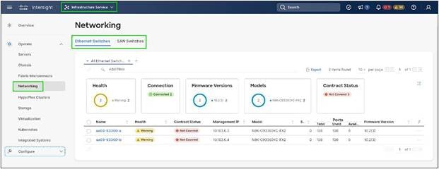
Networking information in Cisco Intersight
Red Hat OpenShift Container Platform on-premises
● OpenShift can run on-premises either on a virtualization layer or directly on bare metal. Integration with bare metal includes use of Redfish virtual media and/or IPMI to directly control local servers through their baseboard management controllers. OpenShift uses the Metal3 project for Kubernetes native bare metal management.
● A typical highly available OpenShift cluster will have three control plane nodes and two or more worker nodes. For a smaller HA footprint, three nodes can each act as part of the control plane and also accept workloads.
● OpenShift includes a rich set of observability features. Metrics, logs, and alerts can be viewed and consumed with built in features and tools, and they can also be published to a variety of third party systems.
● On-premises infrastructure is sometimes disconnected or air gapped for security purposes. OpenShift offers a complete first class experience for securely deploying clusters and delivering updates to all layers of the cluster infrastructure, including the operating system, core Kubernetes, additional Kubernetes related components (observability, storage, network management, developer workflows, and so on), management tooling, and optional Kubernetes operators.
● The systems underlying each node can be optimized using the OpenShift Node Tuning Operator. The Tuned daemon is used in a similar manner as with Red Hat Enterprise Linux; a performance profile is either created or selected from the list of built in profiles, and then the Tuned daemon uses that profile on each system to configure kernel features such as CPU assignments and the low latency and determinism of the real time kernel.
● Each OpenShift release includes a specific version of RHEL CoreOS and all of the OpenShift components. There is no need to provision and maintain a base operating system, because OpenShift includes the OS in its installation and ongoing management.
● OpenShift Virtualization is an add on to OpenShift Container Platform that enables virtual machines to be run and managed in pods alongside containerized workloads. Kubernetes native APIs enable virtual machines to be created, managed, imported, cloned, and live migrated to other nodes.
Red Hat OpenShift Service on AWS
● Red Hat OpenShift Service on AWS (ROSA) provides a fully managed application platform that is seamlessly integrated with AWS services and backed by a global team of SREs.
● ROSA is deployed and billed directly through an AWS account.
● A ROSA cluster can optionally be deployed across multiple availability zones, which enhances the opportunity for the cluster and its workloads to remain highly available through an infrastructure disruption. Best practices should still be followed for application high availability, such as the use of pod disruption budgets, which help keep a service running through voluntary or expected disruptions (such as nodes upgrading in place during a cluster upgrade).
● ROSA has a variety of industry standard security and control certifications, including HIPAA and PCI DSS. A complete list is available in the documentation.
● Auto scaling can be configured to add and remove compute nodes in a ROSA cluster based on pod scheduling pressure. A minimum and maximum number of compute nodes can be configured to ensure that a predictable footprint remains available.
● The ROSA-CLI is used to deploy Red Hat OpenShift on AWS to the AWS environment.
The OpenShift Container Platform cluster uses a virtualized network for pod and service networks. The OVN-Kubernetes Container Network Interface (CNI) plug in is a network provider for the default cluster network. A cluster that uses the OVN-Kubernetes network provider also runs Open vSwitch (OVS) on each node. OVN configures OVS on each node to implement the declared network configuration.
The OVN-Kubernetes default Container Network Interface (CNI) network provider implements the following features:
● Uses OVN (Open Virtual Network) to manage network traffic flows. OVN is a community developed, vendor agnostic network virtualization solution
● Implements Kubernetes network policy support, including ingress and egress rules
● Uses the Geneve (Generic Network Virtualization Encapsulation) protocol rather than VXLAN to create an overlay network between nodes
Internal and external OCP virtual networking designs are shown in Figure 68.
Control plane nodes and worker nodes connect to two networks, to OVN-Kubernetes that OpenShift manages, and then to the physical data center network.
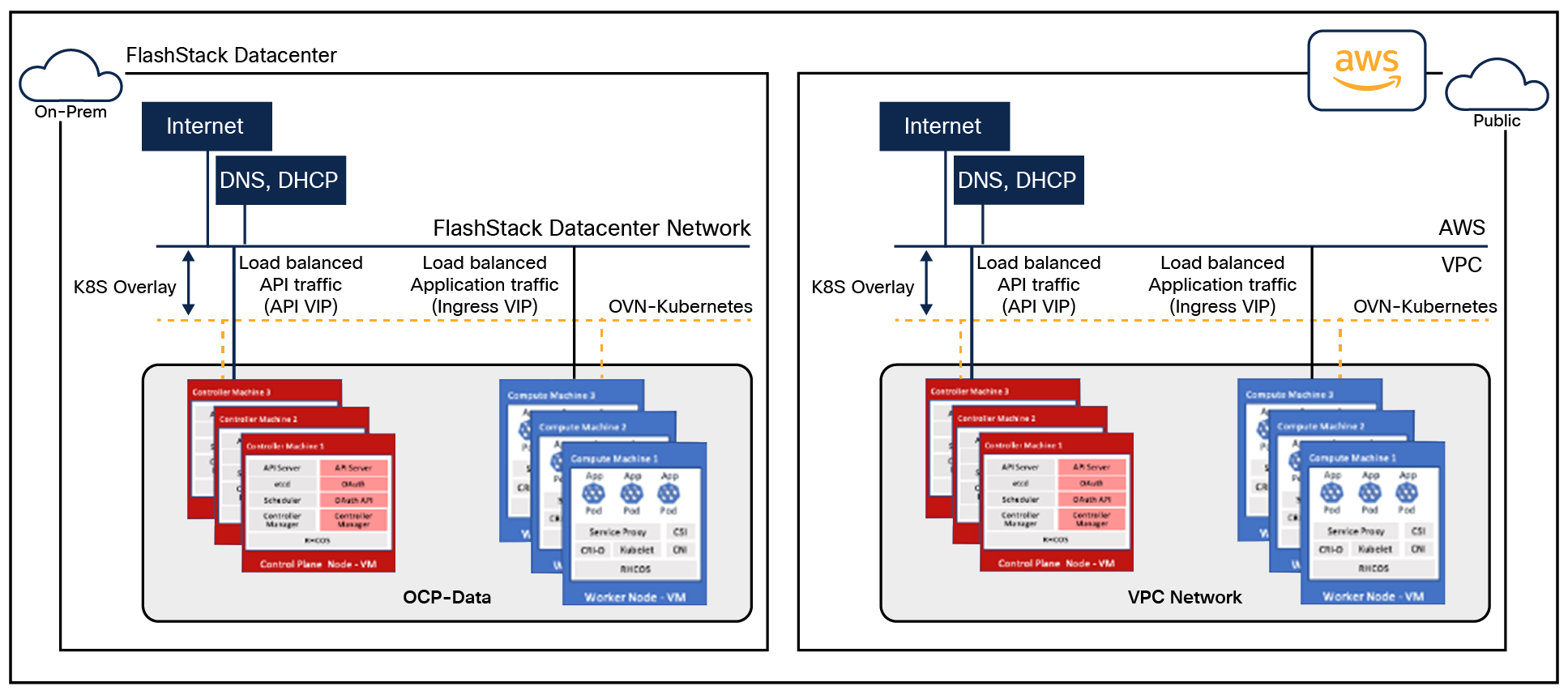
Virtual switching and connectivity diagram
By default, Kubernetes (and OCP) allocates each pod an internal cluster wide IP address that it can use for pod to pod communication. Within a pod, all containers behave as if they are on the same logical host and communicate with each other using localhost, using the ports assigned to the containers. All containers within a pod can communicate with each other using the pod network.
For communication outside the cluster, OCP provides services (node ports, load balancers) and API resources (ingress, route) to expose an application or a service outside cluster so that users can securely access the application or service running on the OCP cluster. API resources, ingress, and routes are used in this solution to expose the application deployed in the OCP cluster.
Portworx Enterprise Kubernetes Storage Platform design considerations
When sizing the disks, it is recommended to configure volumes with adequate capacity for any given work load to be deployed in the cluster. If an application requires 500 GB capacity, then configure more than 500 GB per node using the configuration wizard. This could be a quantity of four 150GB EBS volumes or one large 600GB volume.
Additionally, it is recommended to configure PX-Autopilot to protect applications from downtime related to filling the Persistent Volume Claims (PVCs) in use and the Portworx cluster.
Prerequisites for Portworx on VMware vSphere:
● VMware vSphere version 7.0 or newer.
● kubectl configured on the machine having access to the cluster.
● Portworx does not support the movement of VMDK files from the datastores on which they were created.
● Cluster must be running OpenShift 4 or higher and an infrastructure that meets the minimum requirements for Portworx.
● Virtual machines used for OpenShift nodes for Portworx must have secure boot disabled.
For more information, see: https://docs.portworx.com/install-portworx/prerequisites/
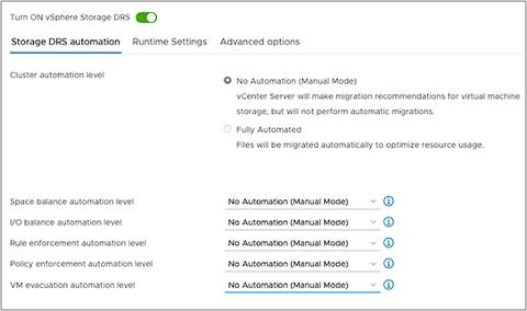
Storage DRS settings configuration on vSphere cluster
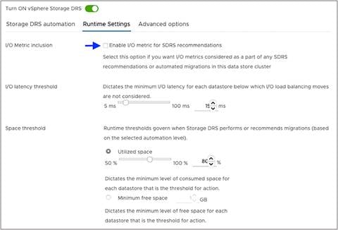
Clear the “Enable I/O metric for the SDRS recommendations” option
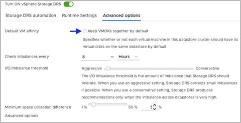
For “Advanced options,” clear “Keep VMDKs together by default”
vCenter environment variables and user privileges for Portworx:
● Create a Kubernetes secret with vCenter user and password.
● Generate specifications for vSphere environment variables such as hostname of vCenter, port number, datastore prefix, and other variables.
● Generate and apply a spec file.
● Administrator has to create a disk template that Portworx will use in the disk template as a reference for creating disks and virtual volumes for PVCs.
Table 4. vCenter user privileges
|
|
|
|
| Allocate space |
Local operations |
Change configuration |
| Browse datastore |
Reconfigure virtual machine |
Add existing disk |
| Low level file operations |
|
Add new disk |
| Remove file |
|
Add or remove device Advanced configuration Change settings Extend virtual disk Modify device settings Remove disk |
Note: If you create a custom role as shown above, make sure to select “Propagate to children” when as signing the user to the role.
Disk provisioning of Portworx on VMware vSphere
● Pure Storage FlashArray//XL provides block storage (vVOLs, FC, and iSCSI) to ESXi hypervisors.
● VMware vSphere datastores are created on the vCenter, and users can create a vSphere datastore cluster.
● vSphere datastore clusters are accessed by Portworx storage.
● Portworx runs on each Kubernetes worker node and, on each node, Portworx creates a disk on the configured shared datastores or datastore clusters.
● Portworx will aggregate all of the disks and form a single storage cluster. Administrators can carve PVCs (persistent volume claims), PVs (persistent volumes), and snapshots from this storage cluster.
● Portworx tracks and manages the disks that it creates. In a failure event, if a new VM spins up, then the new VM will be able to attach to the same disk that was previously created by the node on the failed VM.
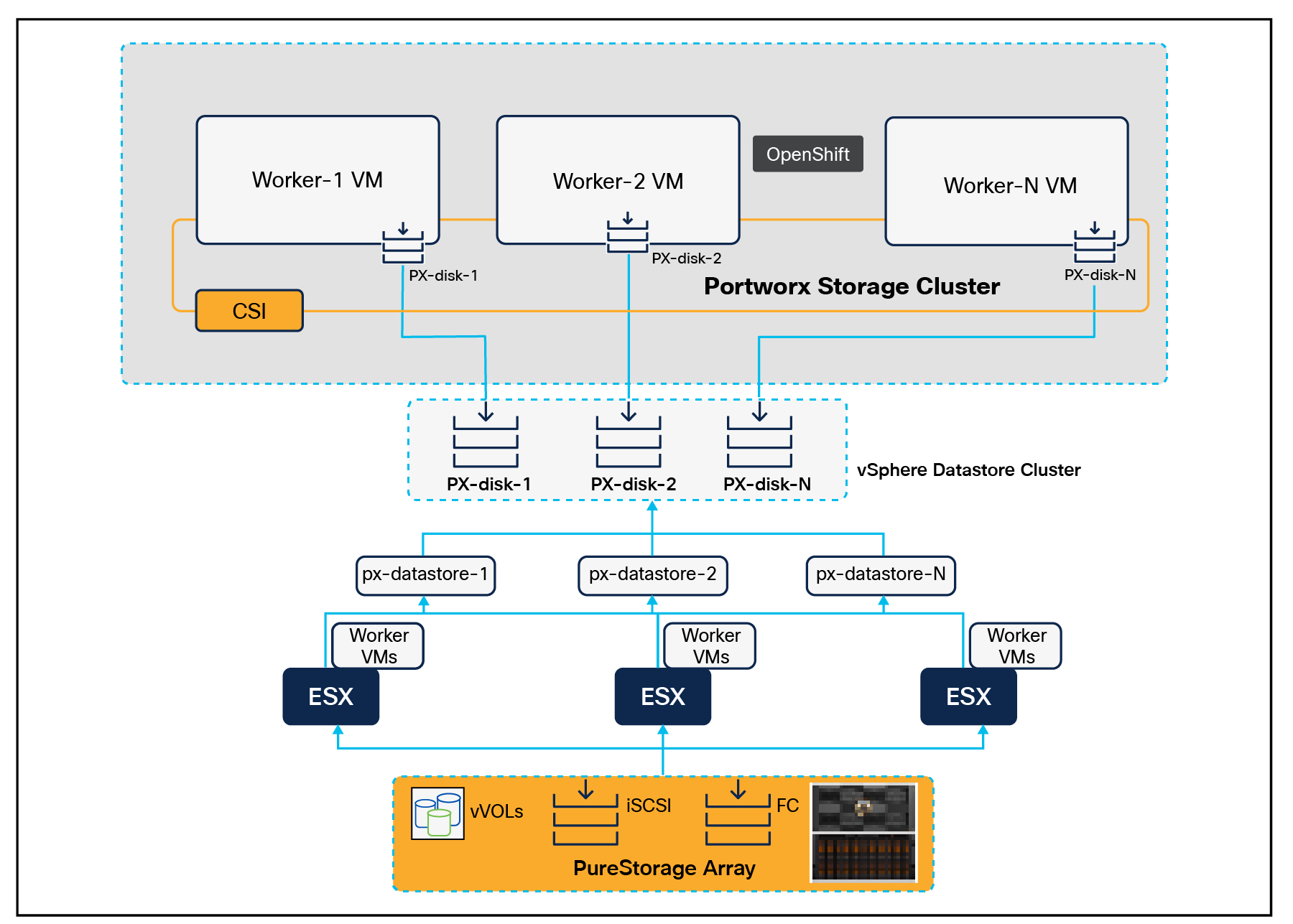
Disk provisioning of Portworx on VMware vSphere
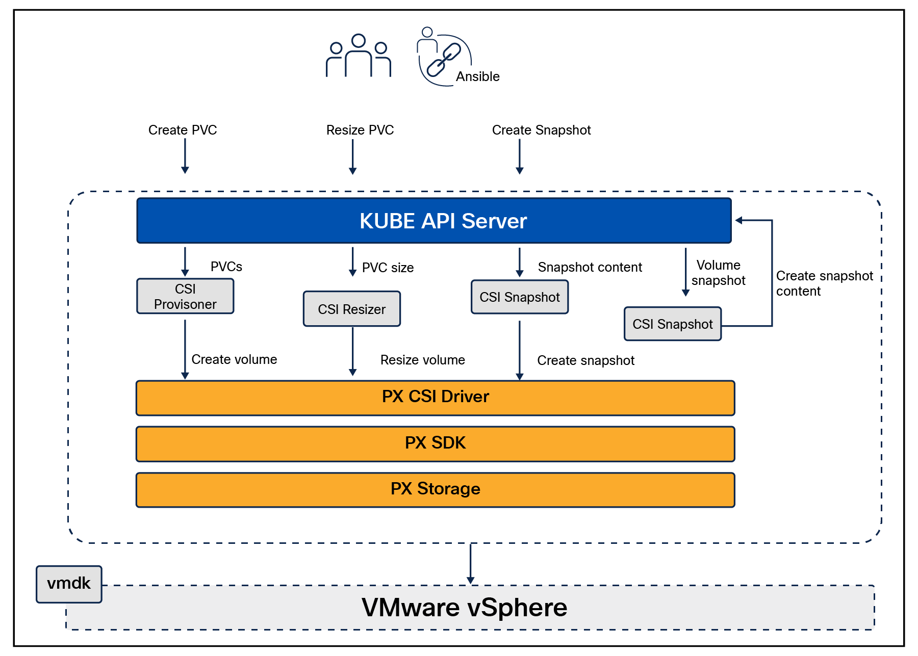
Portworx (PX) CSI architecture
● Portworx provides dynamic disk provisioning on the OpenShift Container Platform running on VMware vSphere.
● Portworx includes a number of default storage classes, which can reference with Persistent Volume Claims (PVCs).
● Portworx CSI driver is an API layer in between the Kubernetes and Portworx SDKs.
● Portworx SDK uses either the default gRPC port 9020 or the default REST gateway port 9021.
● OpenStorage SDK can be plugged into CSI Kubernetes and Docker volumes.
● PX Storage provides cloud native storage for application running in the cloud, on-premises, or on hybrid platforms.
● Here PX Storage communicates with the VMware vSphere virtual machine disk to process the requests.
● Portworx supports:
◦ Provisioning, attaching, and mounting volumes
◦ CSI snapshots
◦ Stork
◦ Volume expansion or resizing
Solution deployment and operations
Deployment hardware and software
This section describes the hardware and software used to deploy a hybrid-cloud infrastructure solution with specific focus on-premises FlashStack Data Center. It is important to note that the validated FlashStack solution explained in this document adheres to a Cisco, Pure Storage, and VMware interoperability matrix to determine support for various software and driver versions. You should use the same interoperability matrix to determine support for components that are different from the current validated design.
Click the following links for more information:
● Pure Storage Interoperability Matrix. Note, this interoperability list will require a support login from Pure:
https://support.purestorage.com/FlashArray/Getting_Started/Compatibility_Matrix.
● Pure Storage FlashStack Compatibility Matrix. Note, this interoperability list will require a support login from Pure:
https://support.purestorage.com/FlashStack/Product_Information/FlashStack_Compatibility_Matrix.
● Cisco UCS Hardware and Software Interoperability Tool:
https://www.cisco.com/web/techdoc/ucs/interoperability/matrix/matrix.html.
● VMware Compatibility Guide:
https://www.vmware.com/resources/compatibility/search.php.
Table 5 lists the required hardware components used to build the validated solution. You are encouraged to review your requirements and adjust the size or quantity of various components as needed.
Table 5. FlashStack Data center with Red Hat OCP hardware components
| Component |
Hardware |
Comments |
| Fabric Interconnects |
Two Cisco UCS Fabric Interconnects such as Cisco UCS 6454 FI |
FI generation dependent on the speed requirement. 4th Generation supports 25Gbps and 5th Generation supports 100Gbps end-to-end. |
| Pure Storage FlashArray |
Pure Storage FlashArray storage with appropriate capacity and network connectivity such as FlashArray //X50 R3, FlashArray//XL170 |
Customer requirements will determine the amount of storage. The FlashArray should support both 25Gbps or 100 Gbps ethernet and 32Gbps or 6416 Gbps FC connectivity. |
| Cisco Nexus Switches |
Two Cisco Nexus 93000 series switches such as Cisco Nexus 93360YC-FX2 |
The switch model is dependent on the number of ports and the port speed required for the planned installation. |
| Cisco MDS Switches |
Two Cisco MDS 9100 series switches, i.e. MDS 9132T |
The supported port speed of the selected MDS switch must match the port speed of the Fabric Interconnect and the FlashArray. |
Table 6 lists the software releases used in the solution. Device drivers, software tools, and Cisco Intersight Assist versions will be explained in the deployment guide.
Table 6. Software components and hardware
| Component |
Software Version |
|
| Network |
Cisco Nexus 9000 C93360YC-FX2 |
10.2(3) |
| Cisco MDS 9132T |
8.4(2c) |
|
| Compute |
Cisco UCS Fabric Interconnect 6454 |
4.2(3b) |
| Cisco UCS UCSX 9108-25G IFM |
4.2(3b) |
|
| Cisco UCS X210C Compute Nodes |
5.0(4a) |
|
| Cisco UCS VIC 14425 installed on X210c |
5.2(3c) |
|
| VMware ESXi |
8.0 |
|
| Storage |
Pure Storage FlashArray//XL170 |
6.3.3 |
| Pure Storage VASA Provider |
3.5 |
|
| Pure Storage Plugin |
5.0.0 |
|
| Kubernetes |
Red Hat OpenShift Container Platform |
4.12 |
| Portworx Enterprise Kubernetes Storage Platform |
2.13 |
|
Automated solution deployment of FlashStack Data Center
This section describes the automated solution deployment of on-premises FlashStack Data Center.
A repository is created in GitHub that Ansible playbooks to configure all the components of FlashStack, including:
● Cisco UCS in Intersight Managed Mode
● Cisco Nexus switches
● Cisco MDS switches
● Pure FlashArray
● VMware ESXi
● VMware vCenter
Figure 74 illustrates the FlashStack with Cisco UCS X-Series modular platform solution implementation workflow with Ansible.
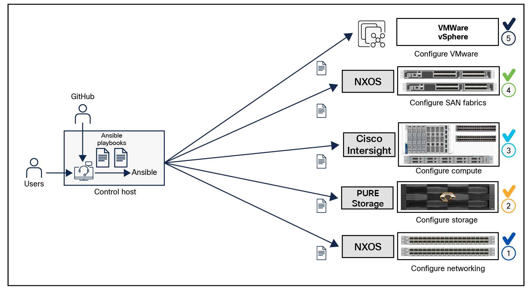
Ansible playbooks to configure the different sections of the solution invoke a set of roles and consume the associated variables that are required to set up the solution. The variables needed for this solution can be split into two categories – user input and defaults / best practices. Based on the installation environment, customers can choose to modify the variables to suit their requirements and then proceed with the automated installation.
Setting up the solution begins with a management workstation that has access to the internet and has a working installation of Ansible. The management workstation runs a variant of Linux or MacOS for ease of use with these command line based tools. Instructions for installing the workstation are not included in this document, but the basic installation and configuration of Ansible is explained. The following is a list of pre requisites:
● To use the Ansible playbooks demonstrated in this document, the management workstation must also have a working installation of Git and access to the GitHub repository. The Ansible playbooks used in this document are cloned from the public repositories, located here: https://github.com/ucs-compute-solutions/FlashStack_OCP_vSphere_Ansible
● The Cisco Nexus switches, Pure Storage, and Cisco UCS must be physically racked, cabled, powered, and configured with the management IP addresses before the Ansible based installation procedure can begin.
● Before running each Ansible playbook to set up the network, storage and Cisco Intersight, various variables must be updated based on the customers environment and specific implementations, with values such as the VLANs, pools, and ports on Cisco UCS, IP addresses for iSCSI interfaces, and values needed for the OCP installation.
For more information, see: Getting Started with Red Hat Ansible
Note: Installing Red Hat OCP and ROSA are performed using automated installers and therefore it will not have the Ansible playbook.
Multicloud GitOps pattern workflow
This section details the workflow of how products and configurations get deployed in the pattern. The diagram below shows what gets deployed in the hub cluster.
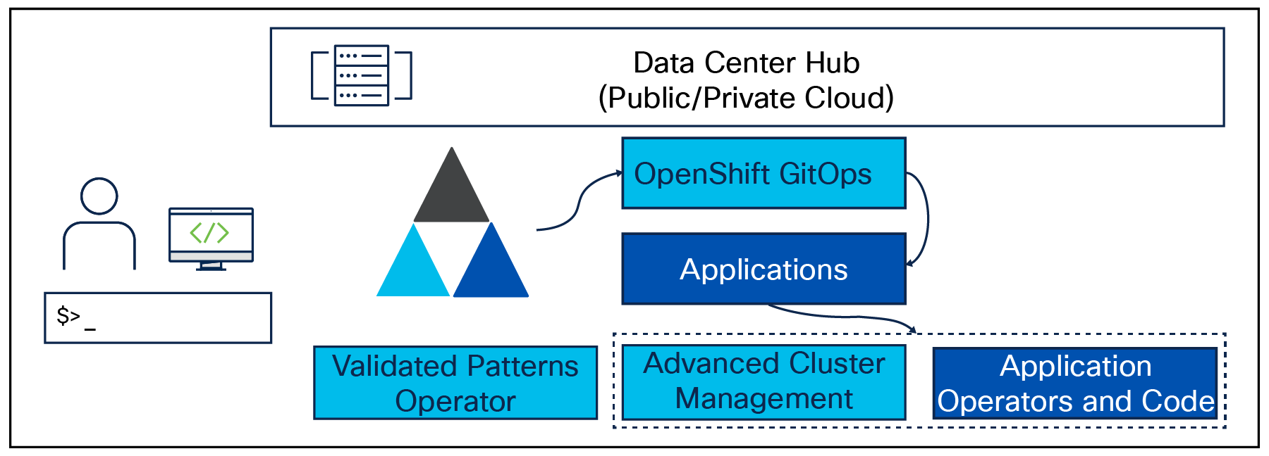
Hub cluster
● Once the operator is deployed, an operator called Validated Patterns Operator gets deployed. The operator contains the information for the Git repository and the branch that will be deployed.
● Validated Patterns Operator deploys OpenShift GitOps with that information.
● GitOps deploys the operators and then the ArgoCD applications defined in the values files.
● One of the applications is Red Hat Advanced Cluster Management (ACM), which is used to manage multiple clusters and policies.
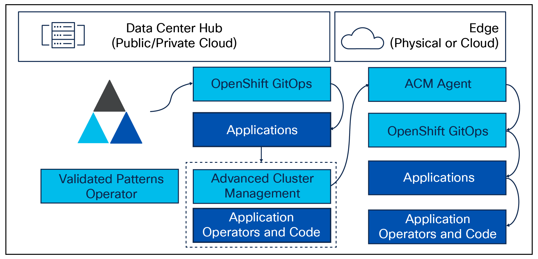
Managed cluster
● When a managed cluster is joined to ACM, or a new cluster is deployed with ACM, it should be assigned to at least one cluster group.
● ACM sees that this managed cluster is part of a cluster group, and after setting up the cluster (including the ACM agent on the managed cluster), it then deploys GitOps and provides it with the information about the cluster group.
● GitOps picks up the associated values file and deploys the operators and configurations/charts.
Deployment of a Multicloud GitOps validated pattern
The pattern can be deployed using the command line from a staging host configured to access the OpenShift hub cluster. Patterns deployment requires several tools. A validated patterns framework removes the need to install and maintain these tools. The pattern.sh script uses a container that includes the necessary tools. The use of that container is why you need to install Podman.
Check the values-*.yaml for changes that are needed before deployment. After changing the values-*.yaml files where needed and pushing them to your Git repository, you can run./pattern.sh make install from your local repository directory; this will deploy the data center / hub cluster for a pattern. Edge clusters are deployed by joining or importing them into ACM on the hub.
Below are the requirements.
1. Red Hat Enterprise Linux 8 or a host configured with OpenShift CLI
2. The same host installed with Git binary and Podman tool
3. An OpenShift cluster (hub cluster)
◦ To create an OpenShift cluster, go to the Red Hat Hybrid-cloud console.
◦ Select OpenShift -> Clusters -> Create cluster.
◦ The cluster must have a dynamic storage class to provision persistent volumes.
4. Optional: A second OpenShift cluster for multicloud demonstration
5. Patterns require cluster storage. Applications also require storage. Therefore, each cluster should have storage class configured with Portworx storage provisioner.
The use of this pattern depends on having at least one running Red Hat OpenShift cluster. However, consider creating a cluster for deploying the GitOps management hub assets and a separate cluster for the managed cluster.
Follow the steps listed below to deploy the Multicloud GitOps pattern.
1. On a Red Hat Enterprise Linux 8 host, install the required tools – Git and Podman.
2. Log in to your cluster. Optionally, set the KUBECONFIG variable for the kubeconfig file path.
oc login
export KUBECONFIG=~/<path_to_kubeconfig>
3. Fork the multicloud-gitops repository on GitHub - https://github.com/validatedpatterns/multicloud-gitops
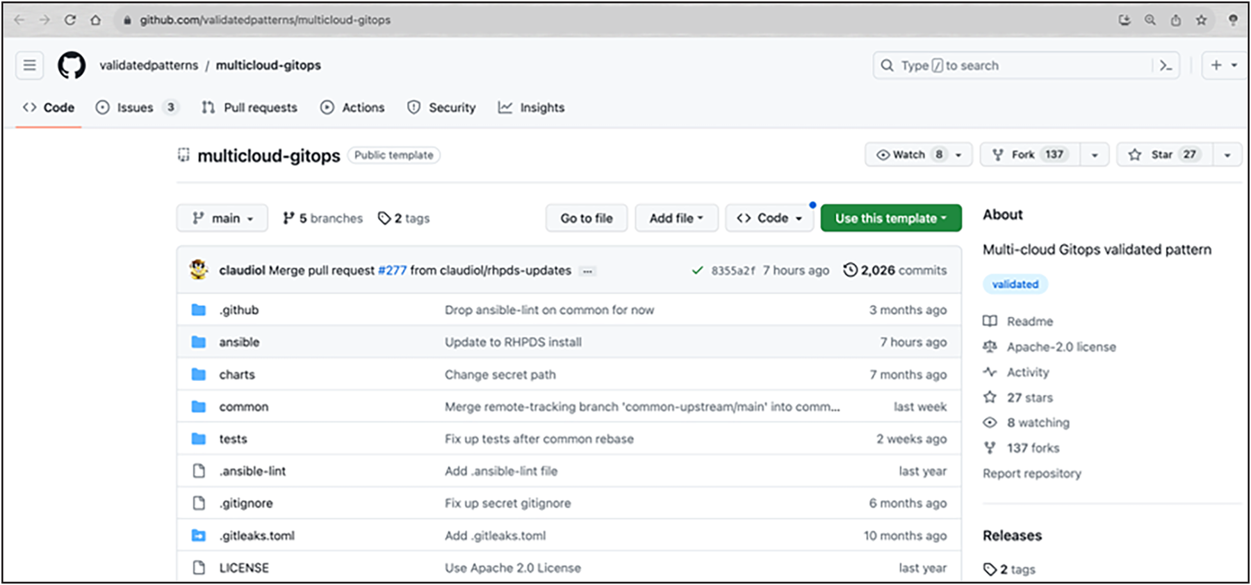
4. Clone the forked copy of this repository.
git clone git@github.com:your-username/multicloud-gitops.git
5. Create a local copy of the secret values file that can safely include credentials. Run the following commands:
cp values-secret.yaml.template ~/values-secret-multicloud-gitops.yaml
vi ~/values-secret-multicloud-gitops.yaml
6. Optionally, customize the deployment for your cluster if any. (Example: changing the name for hub cluster group reference)
Run the following command:
git checkout -b my-branch
vi values-global.yaml
git add values-global.yaml
git commit values-global.yaml
git push origin my-branch
7. Deploy the pattern to your cluster. Run the following command:
./pattern.sh make install
8. Verify that the operators have been installed.
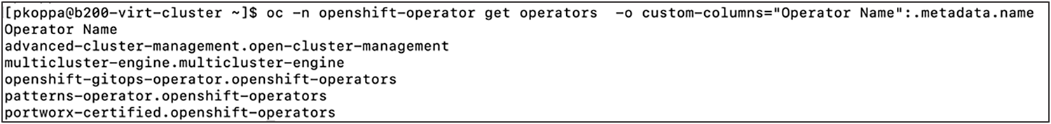
9. Access the GUI of the hub OpenShift cluster. Select Networking -> Routes. Choose multicloud-gitops-hub project. Click on the URL.
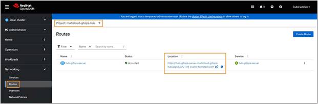
10. Verify that all applications are synchronized.
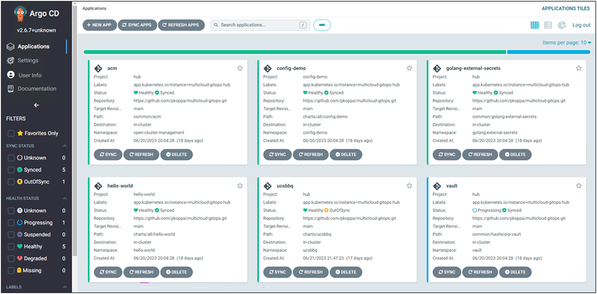
Importing cluster by using Red Hat Advanced Cluster Management (ACM)
Red Hat Advanced Cluster Management gets installed on the hub cluster as part of the pattern deployment. To import other clusters deployed across a hybrid-cloud, do the following steps.
1. In the left navigation panel of the web console, click local cluster. Select All Clusters.
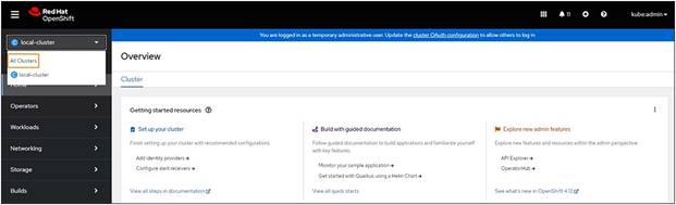
2. The ACM web console is displayed.
3. On the Managed clusters tab, click Import cluster.
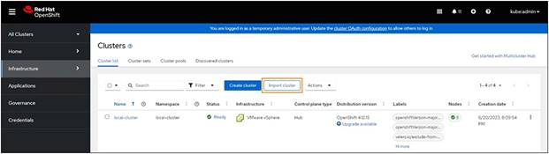
4. On the Import an existing cluster page, enter the cluster name and choose either KUBECONFIG as the "import mode" or provide the server URL and API token for an existing cluster.
5. Add the tag clusterGroup=<Cluster_Group_Name>.
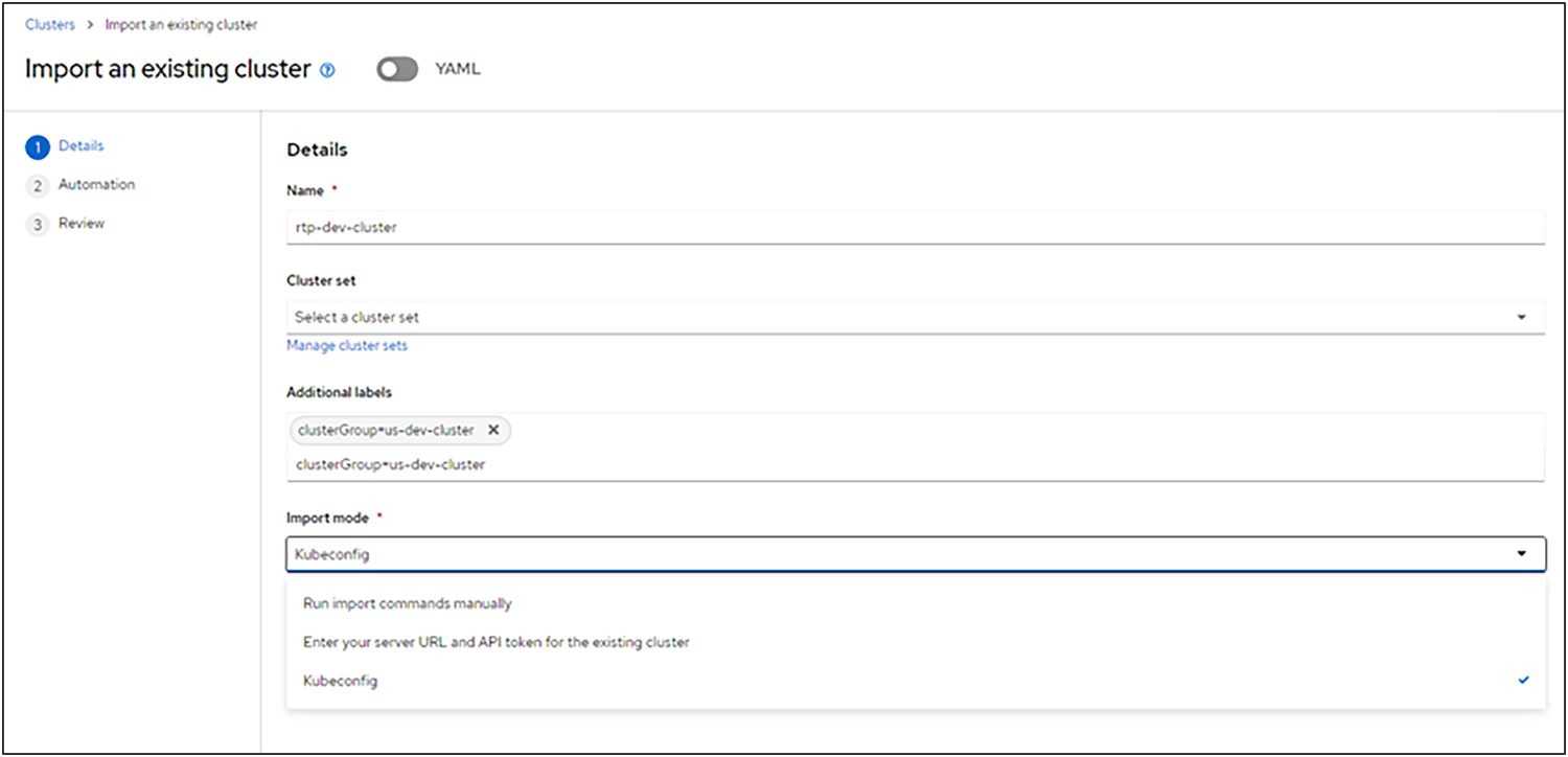
6. Click Import.
7. Repeat the steps for all clusters.
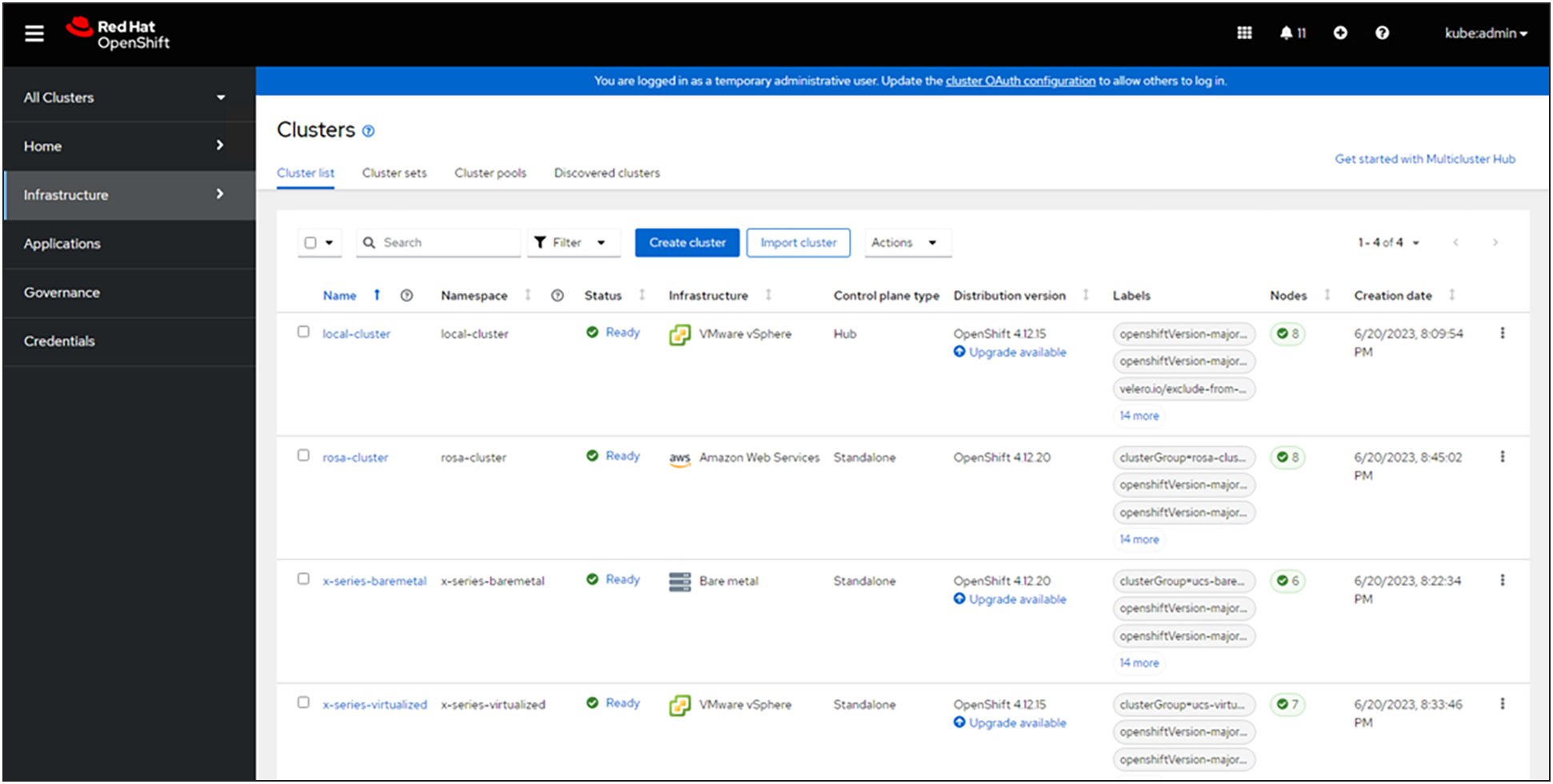
The figure above shows the different cluster deployments imported to ACM.
Customizing Pattern Values file
There are three different types of value files in the patter.
Values global
Used for setting values across all clusters in the pattern. The values are used by the Helm Charts.
values-<clustergroup>
Containing the bill of materials, this file is used to drive the product deployments and configurations of the pattern.
values-secret
Stored locally and not in Git repository. This file allows to set and load secrets (passwords, etc.) using Helm Charts.
Figure 77. shows a sample implementation.
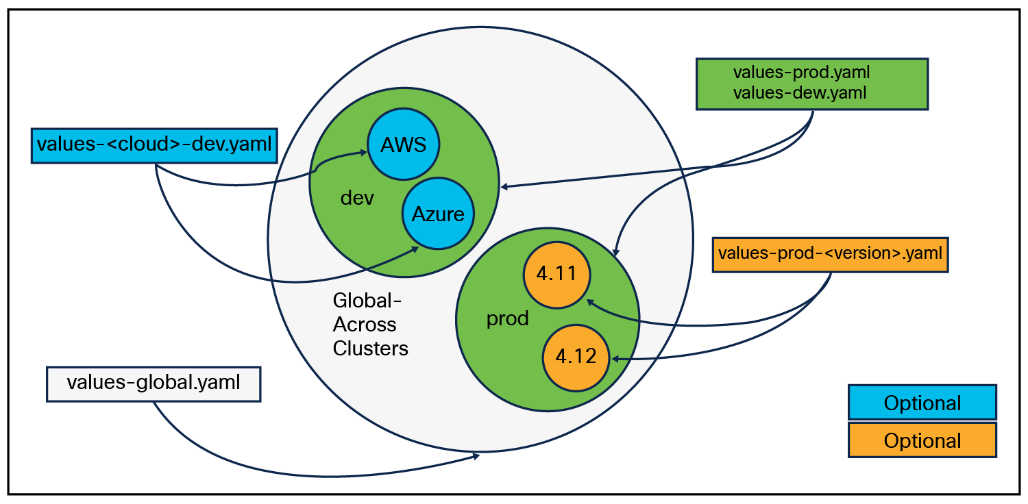
Customizing value files
values-<providerCloud>.yaml is across all cluster groups on that cloud provider, whereas values-AWS-dev.yaml defines values specific to cloud provider AWS on cluster group dev. If you require some specialization for a certain version of OCP or for a specific cloud, a version can be added after the cluster group (values-prod-4.12.yaml). This helps to enable some features in newer versions.
Sample deployment
Figure 78. shows the different sections of a value file.
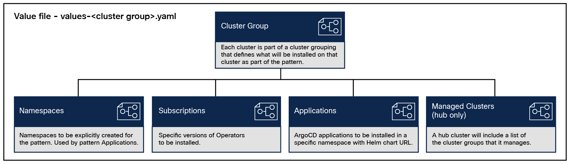
Example code used to deploy Multicloud GitOps patterns and a few applications is present in the GitHub.
Link: https://github.com/pkoppa/multicloud-gitops
values-global.yaml is the first file the framework reads; it defines the name of the main (hub) cluster group. A values-<hub_cluster_name>.yaml file needs to be defined. In the example, we gave the name “hub” to the hub cluster group, and so we called the file values-hub.yaml.
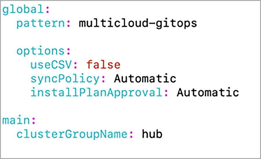
The first section in value-hub.yaml is the name of the hub cluster and a parameter to specify that this spec corresponds to the hub cluster.
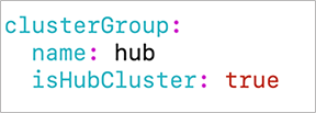
managedClusterGroups in value-hub.yaml defines different cluster groups in the hybrid- and multicloud environment. In the example below, we defined three different cluster group for OpenShift clusters deployed on Cisco UCS bare metal, Cisco UCS virtualized, and ROSA clusters.
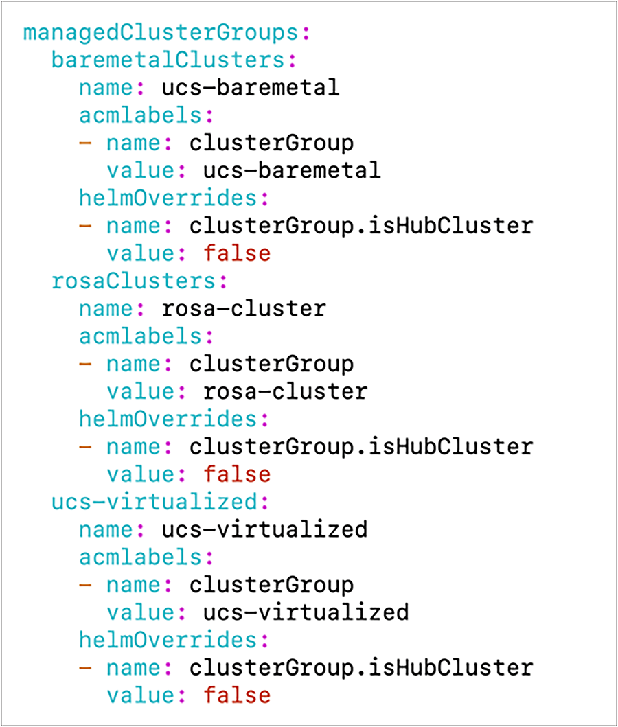
The next sections are common to all values-<clustergroup>.yaml files.
The namespaces section in values-<clustergroup>.yaml defines the namespaces that are expected to be created in the cluster. The pattern will apply these namespaces and create an operator group for each namespace. In the hub cluster, we needed the namespaces given below, and therefore it is defined in the values-hub.yaml
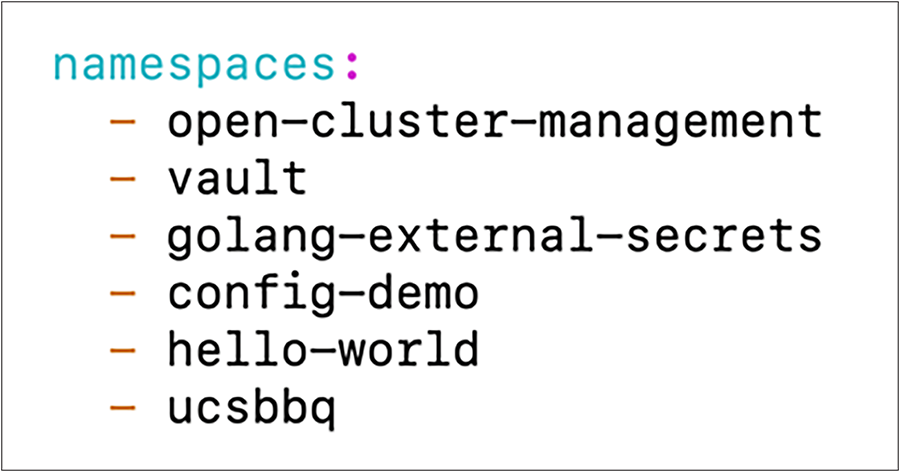
subscriptions define the Red Hat subscription to use.
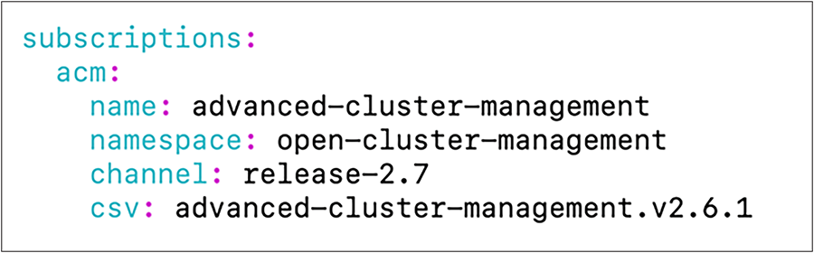
Applications to deploy across-clusters using patterns should have the Helm Chart defined for each application. Helm is the package manager for Kubernetes. Helm uses a packaging format called Charts. A chart is a collection of files that describe a related set of Kubernetes resources. Charts are created as files laid out in a particular directory tree that contains all required resources to deploy the application.
Refer to Helm documentation for creating Helm Charts for applications. Link: https://helm.sh/docs/
Sample applications are present in the “charts” directory in the Multicloud GitOps Git repository. Additional applications along with Helm Charts can be kept in the same directory. It can also be present in a different directory and configure the path with “path” parameter.
In the applications section of values-<clustergroup>.yaml, define all the applications to deploy in that cluster group. In the cluster group called ucs-baremetal, we wanted to deploy three applications, and hence we define the applications as given below in the file values-ucs-baremetal.yaml
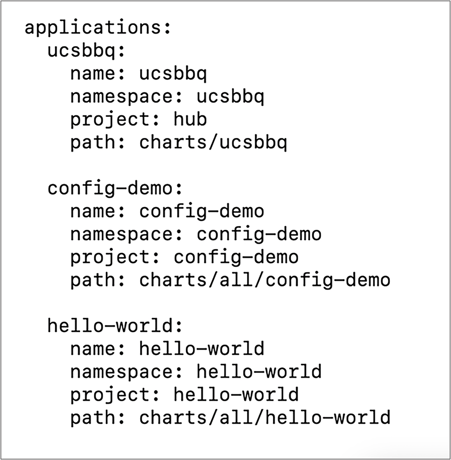
If the application is in a different Git repository, it can also be defined using “repoURL” option, as shown below.
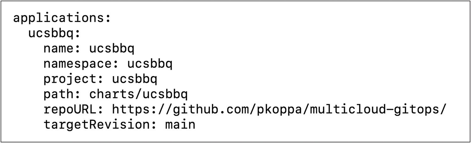
Once all the values files are updated, files can be pushed to the Git repository so that changes (application install/update/delete) are reflected in the corresponding cluster. Mark each cluster in the Red Hat ACM with a label mapped to the cluster group. clusterGroup=<Cluster_Group_Name>. In the example below, a cluster with the name x-series-virtualized is added with a label clusterGroup=ucs-virtualized.
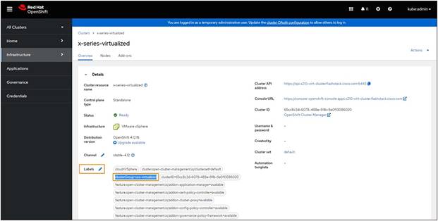
In the Git repository, an application called config demo is defined in the file values-ucs-virtualized.yaml. Hence this application gets installed on all clusters with cluster group ucs-virtualized. These clusters should have the label clusterGroup= ucs-virtualized.
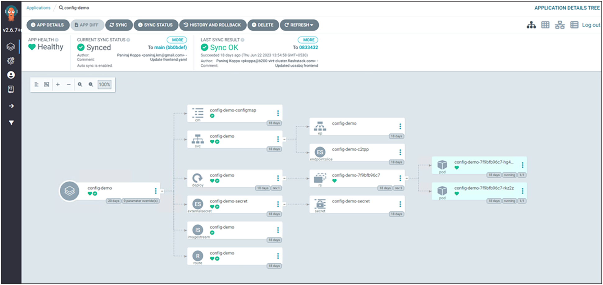
Red Hat validated patterns for Multicloud GitOps with Cisco UCS X-series‒based FlashStack Data center will enable you to use a GitOps approach to manage hybrid and multicloud deployments across on-premises and public cloud environments at scale with minimum effort. It is an ideal solution for organizations investing in hybrid-cloud infrastructure. The solution provides exceptional value for customers looking for predictable performance, high scalability, and reliability.
The solution is built on FlashStack based hybrid-cloud infrastructure validated by Cisco. The on-premises deployment is automated using Red Hat Ansible to provide Infrastructure as Code (IaC) that can be integrated into existing CI/CD pipelines or other forms of automation to accelerate deployments. With Portworx providing storage services, customers can expect persistent volume with low latency, backup restoration, disaster recovery, etc.
Some of the key advantages of integrating Cisco UCS X-Series and Cisco Intersight into the FlashStack infrastructure are:
● Enabling of end-to-end 25/40/100G Ethernet and 32/64G Fibre Channel.
● Simpler and programmable infrastructure.
● Power and cooling innovations and better airflow.
● Fabric innovations for heterogeneous compute and memory composability.
● Innovative cloud operations providing continuous feature delivery.
● Future ready design built for investment protection.
For more information on, refer to the following links:
● Demo video: https://www.youtube.com/watch?v=mTZQNWTH6YU.
● Cisco Validated design - FlashStack for Cloud Native with Cisco Intersight, Red Hat OpenShift, and Portworx Enterprise Design: https://www.cisco.com/c/en/us/td/docs/unified_computing/ucs/UCS_CVDs/flashstack_hc_xseries_ocp412_portworx_design.html.
● GitHub repository for solution deployment: https://github.com/ucs-compute-solutions/FlashStack_OCP_vSphere_Ansible.
● Validated Pattern Home: https://validatedpatterns.io/.
● Multicloud GitOps pattern: https://validatedpatterns.io/patterns/multicloud-gitops.
● Multicloud GitOps repository on GitHub: https://github.com/validatedpatterns/multicloud-gitops.
● Example with sample application: https://github.com/pkoppa/multicloud-gitops.
● Cisco UCS X-Series Modular System: https://www.cisco.com/c/en/us/products/collateral/servers-unified-computing/ucs-x-series-modular-system/solution-overview-c22-2432175.html?ccid=cc002456&oid=sowcsm025665.
● Pattern QuickStart: https://hybrid-cloud-patterns.io/learn/quickstart/.
● Portworx documentation: https://docs.portworx.com.
● Pure Storage Interoperability Matrix. Note, this interoperability list will require a support login form Pure: https://support.purestorage.com/FlashArray/Getting_Started/Compatibility_Matrix.
● Pure Storage FlashStack Compatibility Matrix. Note, this interoperability list will require a support login from Pure: https://support.purestorage.com/FlashStack/Product_Information/FlashStack_Compatibility_Matrix.
● Cisco UCS Hardware and Software Interoperability Tool: https://www.cisco.com/web/techdoc/ucs/interoperability/matrix/matrix.html.
● VMware Compatibility Guide: https://www.vmware.com/resources/compatibility/search.php.