Plan the Deployment
Planning Workflow
You must perform the following planning and information-gathering tasks before attempting to install, configure, and set up your Cisco DNA Center appliance. After you complete these tasks, you can continue by physically installing your appliance in the data center.
-
Review the recommended cabling and switching requirements for standalone and cluster installations. See Interface Cable Connections.
-
Gather the IP addressing, subnetting, and other IP traffic information that you will apply during appliance configuration. See Required IP Addresses and Subnets.
-
Prepare a solution for the required access to web-based resources. See Required Internet URLs and FQDNs and Provide Secure Access to the Internet.
-
Reconfigure your firewalls and security policies for Cisco DNA Center traffic. See Required Network Ports. If you are using Cisco DNA Center to manage a Cisco Software-Defined Access (SD-Access) network, see also Required SD-Access Ports and Protocols.
-
Gather the additional information used during appliance configuration and first-time setup. See Required Configuration Information and Required First-Time Setup Information.
Cisco DNA Center and Cisco Software-Defined Access
You can use Cisco DNA Center to manage any type of network, including networks that employ the Cisco SD-Access fabric architecture. Cisco SD-Access transforms conventional networks into intent-based networks, where business logic becomes a physical part of the network, making it easy to automate day-to-day tasks such as configuration, provisioning, and troubleshooting. The Cisco SD-Access solution reduces the time taken to adapt the network to business needs, improves issue resolutions, and reduces security-breach impacts.
A complete discussion of the Cisco SD-Access solution is outside the scope of this guide. Network architects and administrators planning to implement a Cisco SD-Access fabric architecture for use with Cisco DNA Center can find additional information and guidance from the following resources:
-
For more information on how Cisco DNA Center leverages Cisco SD-Access to automate solutions that are not possible with normal networking approaches and techniques, see Software Defined Access: Enabling Intent-Based Networking.
-
For guidance in using Cisco SD-Access access segmentation to enhance network security, see the Software-Defined Access Segmentation Design Guide.
-
For guidance on deploying SDA with Cisco DNA Center, see the Software-Defined Access Deployment Guide.
-
For more information on the digital network architecture that is the foundation of Cisco DNA Center and the Cisco SD-Access solution, and the roles that other Cisco and third-party products and solutions play in this innovative architecture, see the Cisco DNA Design Zone.
Interface Cable Connections
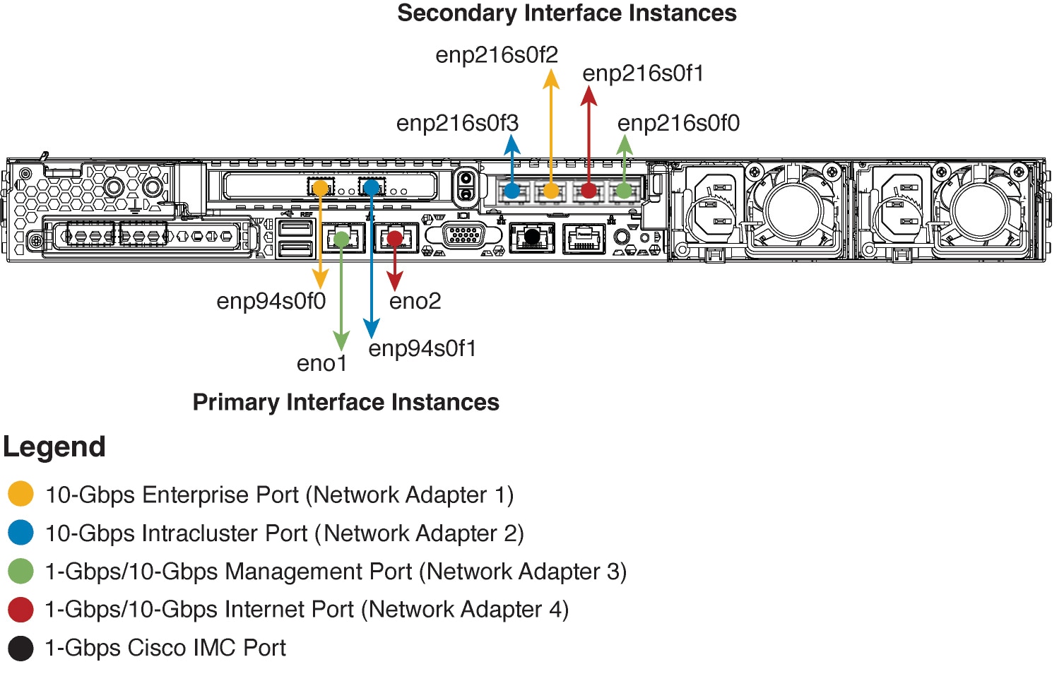
Connect the ports on the appliance to a switch that provides the following types of network access. At a minimum, you must configure the Enterprise and Intracluster port interfaces, as they are required for Cisco DNA Center functionality.
When NIC bonding is enabled on an appliance, a secondary instance of the Enterprise, Intracluster, Management, and Internet ports resides on the Intel X710-DA4 NIC. Connect these ports to a switch that's different from the one that you will connect the primary instance of these ports to (see NIC Bonding Overview).
 Note |
|
-
(Required) 10-Gbps Enterprise Port (Network Adapter 1): The purpose of this port is to enable Cisco DNA Center to communicate with and manage your network. Connect this port to a switch with connections to the enterprise network and configure one IP address with a subnet mask for the port.
Primary instance:
-
On the 44- and 56-core appliance, this is the left-hand port on the Intel X710-DA2 NIC that resides in PCIe slot 1.
-
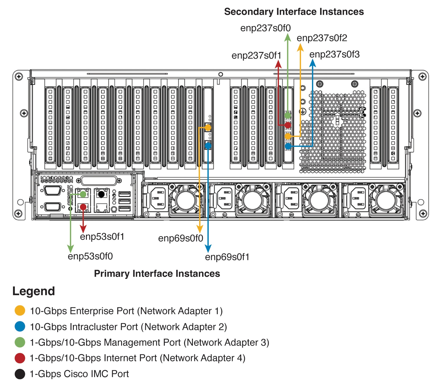
On the 112-core appliance, this is the top 10-Gbps port on the Intel X710-DA2 NIC that resides in PCIe slot 9.
Secondary instance:
-
On the 44- and 56-core appliance, this is the second port on the Intel X710-DA4 NIC that resides in PCIe slot 2.
-
On the 112-core appliance, this is the third 10-Gbps port from the top on the Intel X710-DA4 NIC that resides in PCIe slot 12.
-
-
(Required) 10-Gbps Intracluster Port (Network Adapter 2): The purpose of this port is to enable communications among the primary and secondary nodes in a cluster. Connect this port to a switch with connections to the other nodes in the cluster and configure one IP address with a subnet mask for the port.
Primary instance:
-
On the 44- and 56-core appliance, this is the right-hand port on the Intel X710-DA2 NIC that resides in PCIe slot 1.
-
On the 112-core appliance, this is the bottom 10-Gbps port on the Intel X710-DA2 NIC that resides in PCIe slot 9.
Secondary instance:
-
On the 44- and 56-core appliance, this is the first port on the Intel X710-DA4 NIC that resides in PCIe slot 2.
-
On the 112-core appliance, this is the bottom 10-Gbps port on the Intel X710-DA4 NIC that resides in PCIe slot 12.
-
-
(Optional) 1-Gbps/10-Gbps Management Port (Network Adapter 3): This port provides access to the Cisco DNA Center GUI, allowing users to use the software on the appliance. Connect this port to a switch with connections to your enterprise management network, and configure one IP address with a subnet mask for the port.
Primary instance: Labeled 1 on the appliance's rear panel.
Secondary instance:
-
On the 44- and 56-core appliance, this is the fourth port on the Intel X710-DA4 NIC that resides in PCIe slot 2.
-
On the 112-core appliance, this is the top 10-Gbps port on the Intel X710-DA4 NIC that resides in PCIe slot 12.
-
-
(Optional) 1-Gbps/10-Gbps Internet Port (Network Adapter 4): This port, labeled 2 on the rear panel, is optional. Use it only if you cannot connect the appliance to the Internet (including to your Internet proxy server) using the 10-Gbps Enterprise Port (Network Adapter 1). If you need to use this port, connect it to a switch with connections to your Internet proxy server and configure one IP address with a subnet mask for the port.
Primary instance: Labeled 2 on the appliance's rear panel.
Secondary instance:
-
On the 44- and 56-core appliance, this is the third port on the Intel X710-DA4 NIC that resides in PCIe slot 2.
-
On the 112-core appliance, this is the second 10-Gbps port from the top on the Intel X710-DA4 NIC that resides in PCIe slot 12.
-
-
(Optional, but strongly recommended) 1-Gbps Cisco IMC Port: This port provides browser access to the Cisco Integrated Management Controller (Cisco IMC) out-of-band appliance management interface and its GUI. Its purpose is to allow you to manage the appliance and its hardware. Connect this port to a switch with connections to your enterprise management network and configure an IP address with a subnet mask for the port.
The following figures show the recommended connections for a single-node Cisco DNA Center cluster, as well as the label that's assigned to each interface:
Note |
For both the Management and Internet interface, their primary instance has a bandwidth of 1 Gbps and their secondary instance 10 Gbps. |
Note |
For both the Management and Internet interface, their primary instance has a bandwidth of 1 Gbps and their secondary instance 10 Gbps. |
The connections for each node in a three-node Cisco DNA Center cluster are the same as those for a single-node cluster and use the same ports. Do the following when you cable a three-node cluster:
-
Connect the primary instance of each node's Enterprise, Intracluster, Management, and Internet Port, as well as the Cisco IMC port, to the primary switch.
-
Connect the secondary instance of each node's Enterprise, Intracluster, Management, and Internet Port to the secondary switch.
For more details on each of the ports, see the rear panel diagram and accompanying descriptions for your chassis in Front and Rear Panels.
Note |
Multinode cluster deployments require all the member nodes to be in the same network and at the same site. The appliance does not support distribution of nodes across multiple networks or sites. |
When cabling the 10-Gbps enterprise and cluster ports, note that the ports support only the following media types:
-
SFP-10G-SR-S (Short range, MMF)
-
SFP-10G-LR (Long range, SMF)
-
SFP-H10GB-CU1M (Twinax cable, passive, 1 Meter)
-
SFP-H10GB-CU3M (Twinax cable, passive, 3 Meters)
-
SFP-H10GB-CU5M (Twinax cable, passive, 5 Meters)
-
SFP-H10GB-ACU7M (Twinax cable, active, 7 Meters)
Required IP Addresses and Subnets
Before beginning the installation, you must ensure that your network has sufficient IP addresses available to assign to each of the appliance ports that you plan on using. Depending on whether you are installing the appliance as a single-node cluster or as a primary or secondary node in a three-node cluster, you will need the following appliance port (NIC) addresses:
-
Enterprise Port Address (Required): One IP address with a subnet mask.
-
Cluster Port Address (Required): One IP address with a subnet mask.
-
Management Port Address (Optional): One IP address with a subnet mask.
-
Internet Port Address (Optional): One IP address with a subnet mask. This is an optional port, used only when you cannot connect to the cloud using the Enterprise port. You do not need an IP address for the Internet port unless you must use it for this purpose.
-
CIMC Port Address (Optional, but strongly recommended): One IP address with a subnet mask.
Note |
All of the IP addresses called for in these requirements must be valid IPv4 addresses with valid IPv4 netmasks. Ensure that the addresses and their corresponding subnets do not overlap. Service communication issues can result if they do. |
You will also need the following additional IP addresses and dedicated IP subnets, which are prompted for and applied during configuration of the appliance:
-
Cluster Virtual IP Addresses: One virtual IP (VIP) address per configured network interface per cluster. This requirement applies to three-node clusters and single-node clusters that are likely to be converted into a three-node cluster in the future. You must supply a VIP for each network interface you configure. Each VIP should be from the same subnet as the IP address of the corresponding configured interface. There are four interfaces on each appliance: Enterprise, Cluster, Management, and Internet. At a minimum, you must configure the Enterprise and Cluster port interfaces, as they are required for Cisco DNA Center functionality. An interface is considered configured if you supply an IP address for that interface, along with a subnet mask and one or more associated gateways or static routes. If you skip an interface entirely during configuration, that interface is considered as not configured.
Note the following:
-
If you have a single-node setup and do not plan to convert it into a three-node cluster in the future, you are not required to specify a VIP address. However, if you decide to do so, you must specify a VIP address for every configured network interface (just as you would for a three-node cluster).
-
If the intracluster link for a single-node cluster goes down, the VIP addresses associated with the Management and Enterprise interfaces also go down. When this happens, Cisco DNA Center is unusable until the intracluster link is restored (because the Software Image Management [SWIM] and Cisco Identity Services Engine [ISE] integration is not operational and Cisco DNA Assurance data is not displayed because information cannot be gathered from Network Data Platform [NDP] collectors).
-
Do not use a link-local or nonroutable IP address for the Enterprise or Management interface.
-
-
Default Gateway IP Address: The IP address for your network's preferred default gateway. If no other routes match the traffic, traffic will be routed through this IP address. Typically, you should assign the default gateway to the interface in your network configuration that accesses the internet. For information on security considerations to keep in mind when deploying Cisco DNA Center, see the Cisco Digital Network Architecture Center Security Best Practices Guide.
-
DNS Server IP Addresses: The IP address for one or more of your network's preferred Domain Name System (DNS) servers. During configuration, you can specify multiple DNS server IP addresses by entering them as a space-separated list.
-
(Optional) Static Route Addresses: The IP addresses, subnet masks, and gateways for one or more static routes. During configuration, you can specify multiple static-route IP addresses, netmasks, and gateways by entering them as a space-separated list.
You can set one or more static routes for an interface on the appliance. You should supply static routes when you want to route traffic in a specific direction other than the default gateway. Each of the interfaces with static routes will be set as the device the traffic will be routed through in the IP route command table. For this reason, it is important to match the static route directions with the interface though which the traffic will be sent.
Static routes are not recommended in network device routing tables such as those used by switches and routers. Dynamic routing protocols are better for this. However, you should add static routes where needed, to allow the appliance access to particular parts of the network that can be reached no other way.
-
NTP Server IP Addresses: The DNS-resolvable hostname or IP address for at least one Network Time Protocol (NTP) server.
During configuration, you can specify multiple NTP server IP addresses/masks or hostnames by entering them as a space-separated list. For a production deployment, we recommend that you configure a minimum of three NTP servers.
Specify these NTP servers during preflight hardware synchronization, and again during the configuration of the software on each appliance in the cluster. Time synchronization is critical to the accuracy of data and the coordination of processing across a multihost cluster. Before deploying the appliance in a production environment, make sure that the time on the appliance system clock is current and that the NTP servers you specified are keeping accurate time. If you are planning to integrate the appliance with ISE, you should also ensure that ISE is synchronizing with the same NTP servers as the appliance.
-
Container Subnet: Identifies one dedicated IP subnet for the appliance to use in managing and getting IP addresses for communications among its internal application services, such as Assurance, inventory collection, and so on. By default, Cisco DNA Center configures a link-local subnet (169.254.32.0/20) for this parameter, and we recommend that you use this subnet. If you choose to enter another subnet, ensure that it does not conflict with or overlap any other subnet used by Cisco DNA Center's internal network or any external network. Also ensure that the minimum size of the subnet is 21 bits. The subnet you specify must conform with the IETF RFC 1918 and RFC 6598 specifications for private networks, which support the following address ranges:
-
10.0.0.0/8
-
172.16.0.0/12
-
192.168.0.0/16
-
100.64.0.0/10
For details, see RFC 1918, Address Allocation for Private Internets, and RFC 6598, IANA-Reserved IPv4 Prefix for Shared Address Space.
Important
-
Ensure that you specify a valid CIDR subnet. Otherwise, incorrect bits will be present in the 172.17.1.0/20 and 172.17.61.0/20 subnets.
-
After configuration of your Cisco DNA Center appliance is completed, you cannot assign a different subnet without first reimaging the appliance (see Reimage the Appliance).
-
-
Cluster Subnet: Identifies one dedicated IP subnet for the appliance to use in managing and getting IPs for communications among its infrastructure services, such as database access, the message bus, and so on. By default, Cisco DNA Center configures a link-local subnet (169.254.48.0/20) for this parameter, and we recommend that you use this subnet. If you choose to enter another subnet, ensure that it does not conflict with or overlap any other subnet used by Cisco DNA Center's internal network or any external network. Also ensure that the minimum size of the subnet is 21 bits. The subnet you specify must conform with the IETF RFC 1918 and RFC 6598 specifications for private networks, which support the following address ranges:
-
10.0.0.0/8
-
172.16.0.0/12
-
192.168.0.0/16
-
100.64.0.0/10
For details, see RFC 1918, Address Allocation for Private Internets, and RFC 6598, IANA-Reserved IPv4 Prefix for Shared Address Space.)
If you were to specify 10.10.10.0/21 as your Container subnet, you could also specify a Cluster subnet of 10.0.8.0/21 since these two subnets do not overlap. Also note that the configuration wizard detects overlaps (if any) between these subnets and prompts you to correct the overlap.
Important
-
Ensure that you specify a valid CIDR subnet. Otherwise, incorrect bits will be present in the 172.17.1.0/20 and 172.17.61.0/20 subnets.
-
After configuration of your Cisco DNA Center appliance is completed, you cannot assign a different subnet without first reimaging the appliance (see Reimage the Appliance).
-
When entering an IP address for the Cluster port, container subnet, or cluster subnet, don't specify an address that falls within the 169.254.0.0/23 subnet.
-
The recommended total IP address space for the two Container and Cluster subnets contains 4,096 addresses, broken down into two /21 subnets of 2,048 addresses each. The two /21 subnets must not overlap. The Cisco DNA Center internal services require a dedicated set of IP addresses to operate (a Cisco DNA Center microservice architecture requirement). To accommodate this requirement, you must allocate two dedicated subnets for each Cisco DNA Center system.
One reason the appliance requires this amount of address space is to maintain system performance. Because it uses internal routing and tunneling technologies for east-west (inter-node) communications, using overlapping address spaces forces the appliance to run Virtual Routing and Forwarding (VRF) FIBs internally. This leads to multiple encaps and decaps for packets going from one service to another, causing high internal latency at a very low level, with cascading impacts at higher layers.
Another reason is the Cisco DNA Center Kubernetes-based service containerization architecture. Each appliance uses the IP addresses in this space for each Kubernetes K8 node. Multiple nodes can make up a single service. Currently, Cisco DNA Center supports more than 100 services, each requiring several IP addresses, and new features and corresponding services are being added all the time. The address space requirement is purposely kept large at the start to ensure that Cisco can add new services and features without running out of IP addresses or requiring customers to reallocate contiguous address spaces simply to upgrade their systems.
The services supported over these subnets are also enabled at Layer 3. The Cluster space, in particular, carries data between application and infrastructure services, and is heavily used.
The RFC 1918 and RFC 6598 requirement is because of the requirement by Cisco DNA Center to download packages and updates from the cloud. If the selected IP address ranges do not conform with RFC 1918 and RFC 6598, this can quickly lead to problems with public IP address overlaps.
Required Internet URLs and Fully Qualified Domain Names
The appliance requires secure access to the following table of URLs and Fully Qualified Domain Names (FQDNs).
The table describes the features that make use of each URL and FQDN. You must configure either your network firewall or a proxy server so that IP traffic can travel to and from the appliance and these resources. If you cannot provide this access for any listed URL and FQDN, the associated features will be impaired or inoperable.
For more on requirements for proxy access to the internet, see Provide Secure Access to the Internet.
| In order to... | ...Cisco DNA Center must access these URLs and FQDNs | ||
|---|---|---|---|
|
Download updates to the system and application package software; submit user feedback to the product team. |
Recommended: *.ciscoconnectdna.com:4431 Customers who want to avoid wildcards can specify these URLs instead:
|
||
|
Cisco DNA Center update package. |
|
||
|
Smart Account and SWIM software downloads. |
|||
|
Authenticate with the cloud domain. |
|||
|
Integrate with ThousandEyes. |
|
||
|
Manage Cisco Enterprise Network Function Virtualization Infrastructure Software (NFVIS) devices. |
*.amazonaws.com |
||
|
Allow API calls to enable access to Cisco CX Cloud Success Tracks. Otherwise, the enhancements made to extended configuration-based scanning for the Security Advisories, Bug Identifier, and EOX features that Machine Reasoning Engine (MRE) supports will not operate as expected. |
|||
|
Integrate with Webex. |
|
||
|
User feedback. |
|||
|
Integrate with Cisco Meraki. |
Recommended: *.meraki.com:443 Customers who want to avoid wildcards can specify these URLs instead:
|
||
|
Check SSL/TLS certificate revocation status using OCSP/CRL. |
|
||
|
Allow Cisco authorized specialists to collect troubleshooting data when Cisco DNA Center Remote Support functionality is enabled. |
wss://prod.radkit-cloud.cisco.com:443 |
||
|
Integrate with cisco.com and Cisco Smart Licensing. |
*.cisco.com:443 Customers who want to avoid wildcards can specify these URLs instead:
|
||
|
Connect to the Network-Based Application Recognition (NBAR) cloud. |
prod.sdavc-cloud-api.com:443 |
||
|
Enable the Rogue Management application to detect rogue vendor names. |
|||
|
Render accurate information in site and location maps. |
|
||
|
For Cisco AI Network Analytics data collection, configure your network or HTTP proxy to allow outbound HTTPS (TCP 443) access to the cloud hosts. |
|
||
|
Access a menu of interactive help flows that let you complete specific tasks from the GUI. |
|||
|
Access the licensing service. |
|||
|
Integrate with Cisco Spaces. |
Provide Secure Access to the Internet
By default, the appliance is configured to access the internet in order to download software updates, licenses, and device software, as well as provide up-to-date map information, user feedback, and so on. Providing internet connections for these purposes is a mandatory requirement.
Using an HTTPS proxy server is a reliable way to access remote URLs securely. We recommend that you use an HTTPS proxy server to provide the appliance with the access it needs to the URLs listed in Required Internet URLs and Fully Qualified Domain Names. During appliance installation, you are prompted to enter the URL and port number of the proxy server you want to use for this purpose, along with the proxy's login credentials (if the proxy requires them).
As of this release, the appliance supports communication with proxy servers over HTTP only. You can place the HTTPS proxy server anywhere within your network. The proxy server communicates with the internet using HTTPS, while the appliance communicates with the proxy server via HTTP. Therefore, we recommend that you specify the proxy's HTTP port when configuring the proxy during appliance configuration.
If you need to change the proxy setting after configuration, you can do so using the GUI.
Required Network Ports
The following tables list the well-known network service ports that the appliance uses. You must ensure that these ports are open for traffic flows to and from the appliance, whether you open them using firewall settings or a proxy gateway.
Additional ports, protocols, and types of traffic must be accommodated if you are deploying the appliance in a network that employs SDA infrastructure. For details, see Required SD-Access Ports and Protocols.
Note |
For information on security considerations when deploying Cisco DNA Center, see the Cisco DNA Center Security Best Practices Guide. |
| Port Number | Permitted Traffic | Protocol (TCP or UDP) | ||
|---|---|---|---|---|
|
22 |
SSH |
TCP |
||
|
67 |
BOOTP |
UDP |
||
|
80 |
HTTP |
TCP |
||
|
111 |
NFS (used for Assurance backups) |
TCP and UDP |
||
|
123 |
NTP |
UDP |
||
|
162 |
SNMP |
UDP |
||
|
443 |
HTTPS |
TCP |
||
|
514 |
Syslog |
UDP |
||
|
2049 |
NFS (used for Assurance backups) |
TCP and UDP |
||
|
2068 |
HTTPS |
TCP
|
||
|
2222 |
SSH |
TCP |
||
|
9991 |
Multicast Domain Name System (mDNS) |
TCP |
||
|
20048 |
NFS (used for Assurance backups) |
TCP and UDP |
||
|
21730 |
Application Visibility Service (used for CBAR device communication) |
UDP |
||
|
32767 |
NFS (used for Assurance backups) |
TCP and UDP |
| Port Number | Permitted Traffic | Protocol (TCP or UDP) |
|---|---|---|
|
22 |
SSH (to network devices) |
TCP |
|
23 |
Telnet (to network devices) |
TCP |
|
53 |
DNS |
UDP |
|
80 |
Port 80 can be used for an outgoing proxy configuration. Other common ports (such as 8080) can also be used when a proxy is configured using the Configuration wizard (if a proxy is already in use for your network). To access Cisco-supported certificates and trust pools, configure your network to allow outgoing IP traffic from the appliance to the Cisco addresses listed at: |
TCP |
|
123 |
NTP |
UDP |
|
161 |
SNMP agent |
UDP |
|
443 |
HTTPS |
TCP |
|
5222, 8910 |
Cisco ISE XMP for PxGrid |
TCP |
|
9060 |
Cisco ISE ERS API traffic |
TCP |
Note |
Additionally, you can configure your network to allow outgoing IP traffic from the appliance to the Cisco addresses at: https://www.cisco.com/security/pki/. The appliance uses the IP addresses listed at the above URL to access Cisco-supported certificates and trust pools. |
Required Ports and Protocols for Cisco Software-Defined Access
This topic details the ports, protocols, and types of traffic native to a typical Cisco SD-Access fabric deployment that is similar to the one shown in the following figure.
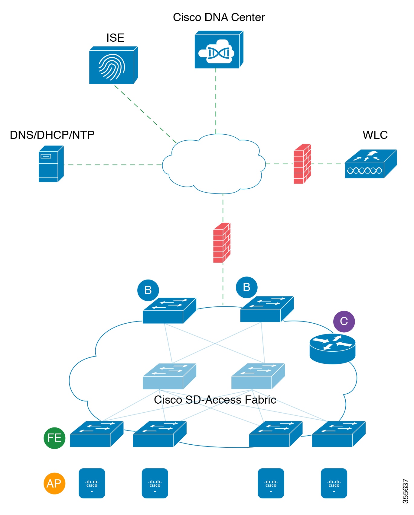
If you have implemented Cisco SD-Access in your network, use the information in the following tables to plan firewall and security policies that secure your Cisco SD-Access infrastructure properly while providing Cisco DNA Center with the access it requires to automate your network management.
| Source Port2 | Source | Destination Port | Destination | Description |
|
Any |
Cisco DNA Center |
UDP 53 |
DNS Server |
From Cisco DNA Center to DNS server |
|
Any |
Cisco DNA Center |
TCP 22 |
Fabric underlay |
From Cisco DNA Center to fabric switches' loopbacks for SSH |
|
Any |
Cisco DNA Center |
TCP 23 |
Fabric underlay |
From Cisco DNA Center to fabric switches' loopbacks for TELNET |
|
Any |
Cisco DNA Center |
UDP 161 |
Fabric underlay |
From Cisco DNA Center to fabric switches' loopbacks for SNMP device discovery |
|
ICMP |
Cisco DNA Center |
ICMP |
Fabric underlay |
From Cisco DNA Center to fabric switches' loopbacks for SNMP device discovery |
|
Any |
Cisco DNA Center |
TCP 443 |
Fabric underlay |
App hosting for switches and NFVIS |
|
Any |
Cisco DNA Center |
UDP 6007 |
Switches and routers |
From Cisco DNA Center to switches and routers for NetFlow |
|
Any |
Cisco DNA Center |
TCP 830 |
Fabric underlay |
From Cisco DNA Center to fabric switches for Netconf (Cisco SD-Access embedded wireless) |
|
UDP 123 |
Cisco DNA Center |
UDP 123 |
Fabric underlay |
From Cisco DNA Center to fabric switches for the initial period during LAN automation |
|
Any |
Cisco DNA Center |
UDP 123 |
NTP Server |
From Cisco DNA Center to NTP server |
|
Any |
Cisco DNA Center |
TCP 22, UDP 161 |
Cisco Wireless Controller |
From Cisco DNA Center to Cisco Wireless Controller |
|
ICMP |
Cisco DNA Center |
ICMP |
Cisco Wireless Controller |
From Cisco DNA Center to Cisco Wireless Controller |
| Any | AP | TCP 32626 | Cisco DNA Center | Used for receiving traffic statistics and packet capture data used by the Cisco DNA Assurance Intelligent Capture (gRPC) feature. |
| Source Port | Source | Destination Port | Destination | Description |
| Any | Cisco DNA Center | TCP 443 | registry.ciscoconnectdna.com | Download Cisco DNA Center package updates |
| Any | Cisco DNA Center | TCP 443 | www.ciscoconnectdna.com | Download Cisco DNA Center package updates |
| Any | Cisco DNA Center | TCP 443 | registry-cdn.ciscoconnectdna.com | Download Cisco DNA Center package updates |
| Any | Cisco DNA Center | TCP 443 | cdn.ciscoconnectdna.com | Download Cisco DNA Center package updates |
| Any | Cisco DNA Center | TCP 443 | software.cisco.com | Download device software |
| Any | Cisco DNA Center | TCP 443 | cloudsso.cisco.com | Validate Cisco.com and Smart Account credentials |
| Any | Cisco DNA Center | TCP 443 | cloudsso1.cisco.com | Validate Cisco.com and Smart Account credentials |
| Any | Cisco DNA Center | TCP 443 | cloudsso2.cisco.com | Validate Cisco.com and Smart Account credentials |
| Any | Cisco DNA Center | TCP 443 | apiconsole.cisco.com | CSSM Smart Licensing API |
| Any | Cisco DNA Center | TCP 443 | sso.cisco.com | Cisco.com credentials and Smart Licensing |
| Any | Cisco DNA Center | TCP 443 | api.cisco.com | Cisco.com credentials and Smart Licensing |
| Any | Cisco DNA Center | TCP 443 | apx.cisco.com | Cisco.com credentials and Smart Licensing |
| Any | Cisco DNA Center | TCP 443 | dashboard.meraki.com | Meraki integration |
| Any | Cisco DNA Center | TCP 443 | api.meraki.com | Meraki integration |
| Any | Cisco DNA Center | TCP 443 | n63.meraki.com | Meraki integration |
| Any | Cisco DNA Center | TCP 443 | dnacenter.uservoice.com | User feedback submission |
| Any | Cisco DNA Center Admin Client | TCP 443 | *.tiles.mapbox.com | Render maps in the browser (for access through proxy; the destination is *.tiles.mapbox.com/*) |
| Any | Cisco DNA Center | TCP 443 | www.mapbox.com | Maps and Cisco Wireless Controller country code identification |
| Any | Cisco DNA Center Admin Client | TCP 443 | data.pendo.io | Collect product telemetry. |
| Source Port3 | Source | Destination Port | Destination | Description |
| UDP 68 | Fabric underlay | UDP 67 | DHCP server | From fabric switches and routers to the DHCP server for DHCP Relay packets initiated by the fabric edge nodes. |
| Any | Fabric underlay | TCP 80 | Cisco DNA Center | From fabric switch and router loopback IPs to Cisco DNA Center for PnP |
| Any | Fabric underlay | TCP 443 | Cisco DNA Center | From fabric switch and router loopback IPs to Cisco DNA Center for image upgrade |
| Any | Fabric underlay | UDP 162 | Cisco DNA Center | From fabric switch and router loopback IPs to Cisco DNA Center for SNMP Traps |
| Any | Fabric underlay | UDP 514 | Cisco DNA Center | From fabric switches and routers to Cisco DNA Assurance |
| Any | Fabric underlay | UDP 6007 | Cisco DNA Center | From fabric switches and routers to Cisco DNA Center for NetFlow |
| Any | Fabric underlay | UDP 123 | Cisco DNA Center | From fabric switches to Cisco DNA Center; used when doing LAN automation |
| ICMP | Fabric underlay | ICMP | Cisco DNA Center | From fabric switch and router loopbacks to Cisco DNA Center for SNMP: device discovery |
| UDP 161 | Fabric underlay | Any | Cisco DNA Center | From fabric switch and router loopbacks to Cisco DNA Center for SNMP: Device Discovery |
| Any | Fabric underlay | UDP 53 | DNS Server | From fabric switches and routers to DNS server for name resolution |
| TCP and UDP 4342 | Fabric underlay, control plane | Any | Fabric routers, switches, and Cisco Wireless Controller |
|
| TCP and UDP 4342 | Fabric underlay, control plane | TCP and UDP 4342 | Fabric routers, switches, and Cisco Wireless Controller |
|
| Any | Fabric underlay | UDP 4789 | Fabric Routers and Switches | Fabric-encapsulated data packets (VXLAN-GPO) |
| Any | Fabric underlay | UDP 1645/1646/1812/1813 | ISE | From fabric switch and router loopback IPs to ISE for RADIUS |
| ICMP | Fabric underlay | ICMP | ISE | From fabric switches and routers to ISE for troubleshooting |
| UDP 1700/3799 | Fabric underlay | Any | ISE | From fabric switches to ISE for care-of address (CoA) |
| Any | Fabric underlay | UDP 123 | NTP Server | From fabric switch and router loopback IPs to the NTP server |
| Any | Control plane | UDP and TCP 4342/4343 | Fabric routers, switches, and Cisco Wireless Controller |
|
| UDP and TCP 4342/4343 | Control plane | Any | Fabric routers, switches, and Cisco Wireless Controller |
|
| Source Port | Source | Destination Port | Destination | Description |
| UDP 5246/5247/5248 | Cisco Wireless Controller | Any | AP IP Address Pool | From Cisco Wireless Controller to an AP subnet for CAPWAP |
| ICMP | Cisco Wireless Controller | ICMP | AP IP Address Pool | From Cisco Wireless Controller to APs allowing ping for troubleshooting |
| Any | Cisco Wireless Controller |
|
Cisco DNA Center | From Cisco Wireless Controller to Cisco DNA Center for Assurance |
| Any | Cisco Wireless Controller | UDP 69/5246/5247 TCP 22 | AP IP Address Pool | From Cisco Wireless Controller to an AP subnet for CAPWAP |
| Any | Cisco Wireless Controller | UDP and TCP 4342/4343 | Control plane | From Cisco Wireless Controller to control-plane loopback IP address |
| Any | Cisco Wireless Controller | TCP 22 | Cisco DNA Center | From Cisco Wireless Controller to Cisco DNA Center for device discovery |
| UDP 161 | Cisco Wireless Controller | Any | Cisco DNA Center | From Cisco Wireless Controller to Cisco DNA Center for SNMP |
| Any | Cisco Wireless Controller | UDP 162 | Cisco DNA Center | From Cisco Wireless Controller to Cisco DNA Center for SNMP traps |
|
Any |
Cisco Wireless Controller |
TCP 16113 |
Cisco Mobility Services Engine (MSE) and Cisco Spectrum Expert |
From Cisco Wireless Controller to Cisco MSE and Spectrum Expert for NMSP |
|
Any |
Cisco Wireless Controller |
UDP 6007 |
Cisco DNA Center |
From wireless controllers to Cisco DNA Center for NetFlow network telemetry |
| ICMP | Cisco Wireless Controller | ICMP | Cisco DNA Center | From Cisco Wireless Controller to allow ping for troubleshooting |
|
Any |
Cisco Wireless Controller and various syslog servers |
UDP 514 |
Cisco Wireless Controller |
Syslog (optional) |
| Any | Cisco Wireless Controller | UDP 53 | DNS Server | From Cisco Wireless Controller to DNS server |
| Any | Cisco Wireless Controller | TCP 443 | ISE | From Cisco Wireless Controller to ISE for Guest SSID web authorization |
| Any | Cisco Wireless Controller | UDP 1645,1812 | ISE | From Cisco Wireless Controller to ISE for RADIUS authentication |
| Any | Cisco Wireless Controller | UDP 1646, 1813 | ISE | From Cisco Wireless Controller to ISE for RADIUS accounting |
| Any | Cisco Wireless Controller | UDP 1700, 3799 | ISE | From Cisco Wireless Controller to ISE for RADIUS CoA |
| ICMP | Cisco Wireless Controller | ICMP | ISE | From Cisco Wireless Controller to ISE ICMP for troubleshooting |
| Any | Cisco Wireless Controller | UDP 123 | NTP server | From Cisco Wireless Controller to NTP server |
| Source Port | Source | Destination Port | Destination | Description |
| UDP 68 | AP IP Address Pool | UDP 67 | DHCP server | From an AP IP Address pool to DHCP server. |
| ICMP | AP IP Address Pool | ICMP | DHCP server | From an AP IP Address pool to ICMP for troubleshooting. |
|
Any |
AP IP Address Pool |
514 |
Various |
Syslog—Destination configurable. Default is 255.255.255.255. |
| Any | AP IP Address Pool | UDP 69/5246/5247/5248 | Cisco Wireless Controller | From an AP IP Address pool to Cisco Wireless Controller for CAPWAP. |
| ICMP | AP IP Address Pool | ICMP | Cisco Wireless Controller | From an AP IP Address pool to Cisco Wireless Controller, allowing ping for troubleshooting. |
| Source Port4 | Source | Destination Port | Destination | Description |
| Any | ISE | TCP 64999 | Border | From ISE to border node for SGT Exchange Protocol (SXP) |
| Any | ISE | UDP 514 | Cisco DNA Center | From ISE to syslog server (Cisco DNA Center) |
| UDP 1645/1646/1812/1813 | ISE | Any | Fabric underlay | From ISE to fabric switches and routers for RADIUS and authorization |
| Any | ISE | UDP 1700/3799 | Fabric underlay, Cisco Wireless Controller |
From ISE to fabric switch and router loopback IP addresses for RADIUS Change of Authorization (CoA). UDP port 3799 must also be open from ISE to the wireless controller for CoA. |
| ICMP | ISE | ICMP | Fabric underlay | From ISE to fabric switches for troubleshooting |
| Any | ISE | UDP 123 | NTP Server | From ISE to NTP server |
| UDP 1812/1645/1813/1646 | ISE | Any | Cisco Wireless Controller | From ISE to Cisco Wireless Controller for RADIUS |
| ICMP | ISE | ICMP | Cisco Wireless Controller | From ISE to Cisco Wireless Controller for troubleshooting |
| Source Port | Source | Destination Port | Destination | Description |
| UDP 67 | DHCP server | UDP 68 | AP IP Address Pool | From DHCP server to fabric APs |
| ICMP | DHCP server | ICMP | AP IP Address Pool | ICMP for troubleshooting: Fabric to DHCP |
| UDP 67 | DHCP server | UDP 68 | Fabric underlay | From DHCP to fabric switches and routers |
| ICMP | DHCP server | ICMP | Fabric underlay | ICMP for troubleshooting: Fabric to DHCP |
| UDP 67 | DHCP server | UDP 68 | User IP Address Pool | From DHCP server to fabric switches and routers |
| ICMP | DHCP server | ICMP | User IP Address Pool | ICMP for troubleshooting: User to DHCP |
| Source Port | Source | Destination Port | Destination | Description |
| UDP 123 | NTP Server | Any | ISE | From NTP server to ISE |
| UDP 123 | NTP Server | Any | Cisco DNA Center | From NTP server to Cisco DNA Center |
| UDP 123 | NTP Server | Any | Fabric underlay | From NTP server to fabric switch and router loopback |
| UDP 123 | NTP Server | Any | Cisco Wireless Controller | From NTP server to Cisco Wireless Controller |
| Source Port | Source | Destination Port | Destination | Description |
| UDP 53 | DNS Server | Any | Fabric underlay | From DNS server to fabric switches |
| UDP 53 | DNS Server | Any | Cisco Wireless Controller | From DNS server to Cisco Wireless Controller |
Required Configuration Information
During appliance configuration, you will be prompted for the following information, in addition to the Required IP Addresses and Subnets:
-
Linux User Name: This is maglev. This user name is the same on all the appliances in a cluster, including the primary node and secondary nodes, and cannot be changed.
-
Linux Password: Identifies the password for the Linux user name maglev. This password ensures secure access to each appliance using the Linux command line. If required, you can assign a different Linux password for each maglev Linux user name on each appliance in a cluster.
You must create the Linux password because there is no default. The password must meet the following requirements:
-
Minimum length of eight characters.
-
Cannot contain a tab or a line break.
-
Contains characters from at least three of the following categories:
-
Uppercase letters (A–Z)
-
Lowercase letters (a–z)
-
Numbers (0–9)
-
Special characters (for example, ! or #)
-
The Linux password is encrypted and hashed in the Cisco DNA Center database. If you are deploying a multinode cluster, you will also be prompted to enter the primary node's Linux password on each of the secondary nodes.
-
-
Password Generation Seed (Optional): Instead of creating a Linux password, you can enter a seed phrase and click Generate Password. The Maglev Configuration wizard generates a random and secure password using this seed phrase. You can further edit the generated password by using the Auto Generated Password field.
-
Administrator Passphrase: Identifies the password used for web access to Cisco DNA Center in a cluster. This is the password for the superuser account admin, which you use to log in to Cisco DNA Center for the first time (see Complete the Quick Start Workflow). You are prompted to change this password when you log in for the first time.
You must create this password because there is no default. The Administrator Passphrase must meet the same requirements as the Linux password, described earlier.
-
Cisco IMC User Password: Identifies the password used for access to the Cisco IMC GUI. The factory default is password, but you are prompted to change it when you first set up Cisco IMC for access using a web browser (see Enable Browser Access to Cisco Integrated Management Controller).
The Cisco IMC user password must meet the same requirements as the Linux password described earlier. It can be changed back to password only by a reset to factory defaults.
-
Primary Node IP Address: Required only when you are installing secondary nodes in a cluster. This is the IP address of the cluster port on the primary node (see Interface Cable Connections).
Required First-Time Setup Information
After you have configured your appliances, log in to Cisco DNA Center and complete the essential setup tasks. During this first-time setup, you should have the following information:
-
New Admin Superuser Password: You will be prompted to enter a new password for the Cisco DNA Center admin super user. Resetting the super user password enhances operational security. This is especially important if, for example, the enterprise staff who installed and configured the Cisco DNA Center appliance is not a Cisco DNA Center user or administrator.
-
Cisco.com Credentials: The Cisco.com user ID and password that your organization uses to register software downloads and receive system communications through email.
-
Cisco Smart Account Credentials: The Cisco.com Smart Account user ID and password your organization uses for managing your device and software licenses.
-
IP Address Manager URL and Credentials: The host name, URL, admin user name, and admin password of the third-party IP address manager (IPAM) server you plan to use with Cisco DNA Center. This release supports InfoBlox and Bluecat.
-
Proxy URL, Port, and Credentials: The URL (host name or IP address), port number, user name, and user password of the proxy server you plan to use with Cisco DNA Center in order to get updates to the Cisco DNA Center software, manage device licenses, and retrieve other downloadable content.
-
Cisco DNA Center Users: User names, passwords, and privilege settings for the new Cisco DNA Center users you will be creating. We recommend that you always use one of these new user accounts for all your normal Cisco DNA Center operations. Avoid using the admin super user account for activities, except reconfiguring Cisco DNA Center and operations where super user privileges are explicitly required.
For details about how to launch and respond to the first-time setup wizard that prompts you for this information, see Complete the Quick Start Workflow.
You will also need the following information to complete the remaining setup tasks, which can be done after your first login:
-
ISE Server IP and Credentials: You will need the Cisco ISE server IP address and credentials, administrative user name, and password. These are needed to log in to and configure your organization's ISE server to share data with Cisco DNA Center, as explained in Integrate Cisco ISE With Cisco DNA Center.
Installation of or upgrade to Cisco DNA Center checks to see if Cisco ISE is configured as an authentication and policy (AAA) server. If the correct version of Cisco ISE is already configured, you can start migrating group policy data from Cisco ISE to Cisco DNA Center.
If Cisco ISE is not configured, or if the required version of Cisco ISE is not present, Cisco DNA Center installs, but Group Based Policy is disabled. You must install or upgrade Cisco ISE and connect it to Cisco DNA Center. You can then start the data migration.
Cisco DNA Center data present in the previous version is preserved when you upgrade. The data migration operation merges data from Cisco DNA Center and Cisco ISE. If the migration encounters a conflict, preference is given to data from Cisco ISE.
If Cisco DNA Center becomes unavailable, and it is imperative to manage policies before Cisco DNA Center becomes available once more, there is an option in Cisco ISE to override the Read-Only setting. This allows you to make policy changes directly in Cisco ISE. After Cisco DNA Center is available again, you must disable the Read-Only override on Cisco ISE, and re-synchronize the policy data on Cisco DNA Center Group Based Access Control Settings page. Only use this option when absolutely necessary, since changes made directly in Cisco ISE are not propagated to Cisco DNA Center.
-
Authorization and Policy Server Information: If you are using Cisco ISE as your authentication and policy server, you will need the same information listed in the previous bullet, plus the ISE CLI user name, CLI password, server FQDN, a subscriber name (such as cdnac ), the ISE SSH key (optional), the protocol choice (RADIUS or TACACS), the authentication port, the accounting port, and retry and timeout settings.
If you are using an authorization and policy server that is not Cisco ISE, you will need the server's IP address, protocol choice (RADIUS or TACACS), authentication port, accounting port, and retry and timeout settings.
This information is required to integrate Cisco DNA Center with your chosen authentication and policy server, as explained in Configure Authentication and Policy Servers.
-
SNMP Retry and Timeout Values: This is required to set up device polling and monitoring, as explained in Configure SNMP Properties.