Review the Cisco DNA Center Appliance Features
Appliance Hardware Specifications
Cisco supplies Cisco Digital Network Architecture (DNA) Center in the form of a rack-mountable, physical appliance. The second-generation Cisco DNA Center appliance consists of either a Cisco Unified Computing System (UCS) C220 M5 small form-factor (SFF) chassis or Cisco UCS C480 M5 chassis, both with the addition of one Intel X710-DA2 network interface card (NIC) and one Intel X710-DA4 NIC. Six versions of the second-generation appliance are available:
-
44-core appliance: Cisco part number DN2-HW-APL
-
44-core promotional appliance: Cisco part number DN2-HW-APL-U
-
56-core appliance: Cisco part number DN2-HW-APL-L
-
56-core promotional appliance: Cisco part number DN2-HW-APL-L-U
-
112-core appliance: Cisco part number DN2-HW-APL-XL
-
112-core promotional appliance: Cisco part number DN2-HW-APL-XL-U
The following tables summarize the appliance's hardware specifications.
| Feature | Description | ||
|---|---|---|---|
|
Chassis |
One rack-unit (1RU) chassis. |
||
|
Processors |
Two 22-core Intel 6238 2.1 GHz processors |
||
|
Memory |
Eight 32 GB DDR4 2933 MHz registered DIMMs (RDIMMs) |
||
|
Storage |
|
||
|
Disk Management (RAID) |
|
||
|
Network and Management I/O |
Supported connectors:
The following connectors are available but not typically used in the day-to-day operation of Cisco DNA Center:
|
||
|
Power |
Two 770 W AC power supplies. Redundant as 1+1. |
||
|
Cooling |
Seven hot-swappable fan modules for front-to-rear cooling. |
||
|
Video |
Video Graphics Array (VGA) video resolution up to 1920 x 1200, 16 bpp at 60 Hz, and up to 512 MB of video memory (8 MB is allocated by default). |
| Feature | Description | ||
|---|---|---|---|
|
Chassis |
One rack-unit (1RU) chassis. |
||
|
Processors |
Two 28-core Intel 8280 2.7 GHz processors |
||
|
Memory |
Twelve 32 GB DDR4 2933 MHz RDIMMs |
||
|
Storage |
|
||
|
Disk Management (RAID) |
|
||
|
Network and Management I/O |
Supported connectors:
The following connectors are available but not typically used in the day-to-day operation of Cisco DNA Center:
|
||
|
Power |
Two 770 W AC power supplies. Redundant as 1+1. |
||
|
Cooling |
Seven hot-swappable fan modules for front-to-rear cooling. |
||
|
Video |
Video Graphics Array (VGA) video resolution up to 1920 x 1200, 16 bpp at 60 Hz, and up to 512 MB of video memory (8 MB is allocated by default). |
| Feature | Description | ||
|---|---|---|---|
|
Chassis |
Four rack-unit (4RU) chassis. |
||
|
Processors |
Two CPU modules, each with two 28-core Intel 8276 2.2 GHz processors |
||
|
Memory |
Twenty-four 32 GB DDR4 2933 MHz RDIMMs |
||
|
Storage |
|
||
|
Disk Management (RAID) |
|
||
|
Network and Management I/O |
Supported connectors:
The following connectors are available but not typically used in the day-to-day operation of Cisco DNA Center:
|
||
|
Power |
Four 1600 W AC power supplies. Redundant as 3+1 (must be configured via the Cisco Integrated Management Controller). |
||
|
Cooling |
Four hot-swappable fan modules with two fans in each for front-to-rear cooling. |
||
|
Video |
VGA video resolution up to 1600 x1200, 16 bpp at 60 Hz, and up to 256 MB of video memory. |
Front and Rear Panels
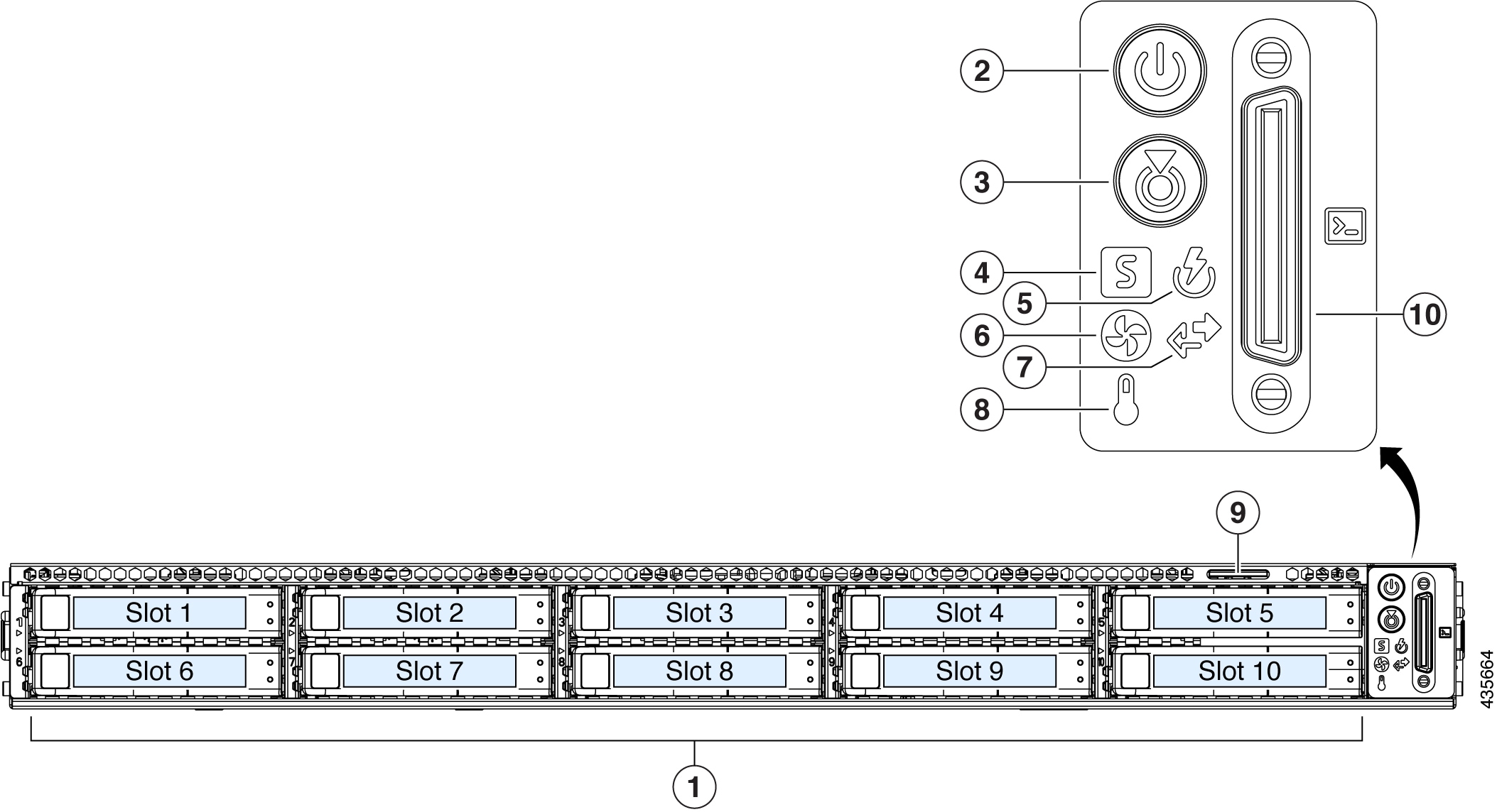
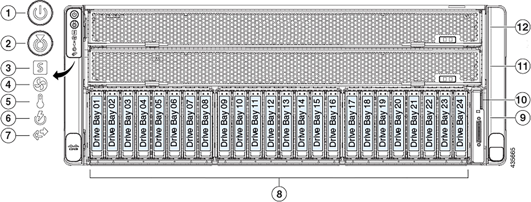
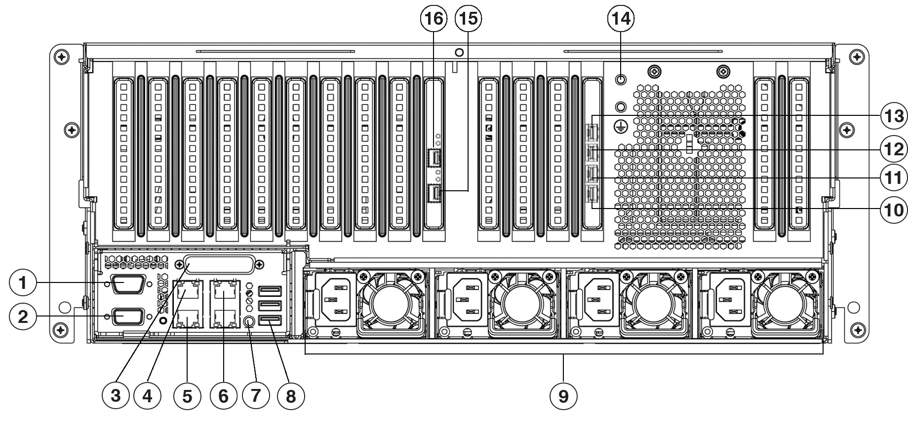
The following figures and tables describe the front and rear panels of the Cisco DNA Center appliance.
 Note |
If you are viewing this guide on cisco.com, click any of its figures to view a full-sized version. |

| Component | Description |
|---|---|
|
1 |
A total of 10 drives are available on the appliance:
Each installed drive has a fault LED and an activity LED. When the drive fault LED is:
When the drive activity LED is:
|
|
2 |
Power button/power status LED. When the LED is:
|
|
3 |
Unit identification button and LED. When the LED is:
|
|
4 |
System status LED. When the LED is:
|
|
5 |
Power supply status LED. When the LED is:
|
|
6 |
Fan status LED. When the LED is:
|
|
7 |
Network link activity LED. When the LED is:
|
|
8 |
Temperature status LED. When the LED is:
|
|
9 |
Pull-out asset tag. |
|
10 |
KVM connector. Used with a KVM cable that provides two USB 2.0, one VGA, and one serial connector. |

| Component | Description | ||
|---|---|---|---|
|
1 |
Power button/power status LED. When the LED is:
|
||
|
2 |
Unit identification button and LED. When the LED is:
|
||
|
3 |
System status LED. When the LED is:
|
||
|
4 |
Fan status LED. When the LED is:
|
||
|
5 |
Temperature status LED. When the LED is:
|
||
|
6 |
Power supply status LED. When the LED is:
|
||
|
7 |
Network link activity LED. When the LED is:
|
||
|
8 |
A total of 20 drives are available on the appliance:
Each installed drive has a fault LED and an activity LED. When the drive fault LED is:
When the drive activity LED is:
|
||
|
9 |
KVM connector. Used with a KVM cable that provides two USB 2.0, one VGA, and one serial connector. |
||
|
10 |
Pull-out asset tag. |
||
|
11 |
CPU module bay 1. |
||
|
12 |
CPU module bay 2. |

 Note |
If NIC bonding has been enabled on your Cisco DNA Center appliance, two instances of the Enterprise, Intracluster, Management, and Internet port are available to configure and use. See NIC Bonding Overview for more information. |
| Callout | Description | ||
|---|---|---|---|
|
1 |
Modular LAN-on-motherboard (mLOM) card bay (x16 PCIe lane) |
||
|
2 |
Two USB 3.0 ports |
||
|
3, 10 |
1-Gbps/10-Gbps Management Port (Network Adapter 3): This Ethernet port can support 1 Gbps and 10 Gbps, depending on the link partner capability. It is identified as Network Adapter 3 in the Maglev Configuration wizard. Connect this port to a switch that provides access to your enterprise management network.
This port has a link status LED and a link speed LED. When the status LED is:
When the speed LED is:
|
||
|
4, 11 |
1-Gbps/10-Gbps Internet Port (Network Adapter 4): This Ethernet port can support 1 Gbps and 10 Gbps, depending on the link partner capability. It is identified as Network Adapter 4 in the Maglev Configuration wizard. This port is optional and is used for connecting to the Internet when it is not possible to do so via the 10-Gbps Enterprise port. Connect to the Internet or a proxy server that has connections to the Internet.
This port has a link status LED and a link speed LED. When the link status LED is:
When the speed LED is:
|
||
|
5 |
VGA video port (DB-15). |
||
|
6 |
1-Gbps Cisco IMC Port: This is the embedded port to the right of the VGA video port and to the left of the RJ45 serial port. It is assigned an IP address when you enable browser access to the appliance's Cisco IMC GUI (see Enable Browser Access to Cisco Integrated Management Controller). This port is reserved for out-of-band management of the appliance chassis and software. Connect this port to a switch that provides access to your enterprise management network. This port has a link status LED and a link speed LED. When the link status LED is:
When the speed LED is:
|
||
|
7 |
Serial port (RJ-45 connector) |
||
|
8 |
Rear unit identification button and LED |
||
|
9 |
Power supplies (up to two: redundant as 1+1). Each power supply has a power supply fault LED and an AC power LED. When the fault LED is:
When the AC Power LED is:
For more details, see Power Specifications. |
||
|
12, 15 |
10-Gbps Enterprise Port (Network Adapter 1): This port is identified as Network Adapter 1 in the Maglev Configuration wizard. Connect it to a switch with connections to the Enterprise network.
This port has a link status (ACT) LED and a link speed (LINK) LED. When the link status LED is:
When the speed LED is:
|
||
|
13, 14 |
10-Gbps Intracluster Port (Network Adapter 2): This port is identified as Network Adapter 2 in the Maglev Configuration wizard. Connect this port to a switch with connections to the other nodes in the cluster.
This port is located on the Intel X710-DA4 NIC, which is located in the appliance's PCIe riser 2/slot 2. This port has a link status (ACT) LED and a link speed (LINK) LED. When the link status LED is:
When the link speed LED is:
|
||
|
16 |
Threaded holes for dual-hole grounding lug. |


 Note |
If NIC bonding has enabled on your Cisco DNA Center appliance, two instances of the Enterprise, Intracluster, Management, and Internet port are available to configure and use. See NIC Bonding Overview for more information. |
| Callout | Description | ||
|---|---|---|---|
|
1 |
Serial port COM 1 (DB-9 connector) |
||
|
2 |
VGA video port (DB-15 connector) |
||
|
3 |
Not used at this time |
||
|
4, 13 |
1-Gbps/10-Gbps Management Port (Network Adapter 3): This Ethernet port can support 1 Gbps and 10 Gbps, depending on the link partner capability. It is identified as Network Adapter 3 in the Maglev Configuration wizard. Connect this port to a switch that provides access to your enterprise management network.
This port has a link status LED and a link speed LED. When the status LED is:
When the speed LED is:
|
||
|
5, 12 |
1-Gbps/10-Gbps Internet Port (Network Adapter 4): This Ethernet port can support 1 Gbps and 10 Gbps, depending on the link partner capability. It is identified as Network Adapter 4 in the Maglev Configuration wizard. This port is optional and is used for connecting to the Internet when it is not possible to do so via the 10-Gbps Enterprise port. Connect to the Internet or a proxy server that has connections to the Internet.
This port has a link status LED and a link speed LED. When the link status LED is:
When the speed LED is:
|
||
|
6 |
1-Gbps Cisco IMC Port: This is the 10/100/1000 Ethernet dedicated management port (Base-T), which is located to the right of the Management port. It is identified as 3 on the rear panel. This port is assigned an IP address when you enable browser access to the appliance's Cisco IMC GUI (see Enable Browser Access to Cisco Integrated Management Controller). It is reserved for out-of-band management of the appliance chassis and software. Connect this port to a switch that provides access to your enterprise management network. This port has a link status LED and a link speed LED. When the link status LED is:
When the speed LED is:
|
||
|
7 |
Rear identification button/LED |
||
|
8 |
Three USB 3.0 ports |
||
|
9 |
Power supplies 1 – 4: hot-swappable and redundant as 3+1 (configured in Cisco IMC). See Power Specifications for more information. |
||
|
10, 15 |
10-Gbps Intracluster Port (Network Adapter 2): This port is identified as Network Adapter 2 in the Maglev Configuration wizard. Connect this port to a switch with connections to the other nodes in the cluster.
This port has a link status (ACT) LED and a link speed (LINK) LED. When the link status LED is:
When the link speed LED is:
|
||
|
11, 16 |
10-Gbps Enterprise Port (Network Adapter 1): This port is identified as Network Adapter 1 in the Maglev Configuration wizard. If NIC bonding is enabled on your appliance, connect this port to a switch with connections to the enterprise network.
This port has a link status (ACT) LED and a link speed (LINK) LED. When the link status LED is:
When the speed LED is:
|
||
|
14 |
Threaded holes for dual-hole grounding lug. |
Physical Specifications
The following table lists the physical specifications for the appliance. Unless indicated, the specifications apply to the 44-, 56-, and 112-core appliances.
| Description | Specification |
|---|---|
|
Height |
44- and 56-core appliance: 1.7 in. (4.32 cm) 112-core appliance: 6.9 in. (17.6 cm) |
|
Width |
44- and 56-core appliance:
112-core appliance: 19.0 in. (48.3 cm) |
|
Depth (length) |
44- and 56-core appliance:
112-core appliance: 32.7 in. (83.1 cm) |
|
Front Clearance |
3 in. (76 mm) |
|
Side Clearance |
1 in. (25 mm) |
|
Rear Clearance |
6 in. (152 mm) |
|
Maximum weight (fully loaded chassis) |
44- and 56-core appliance: 37.5 lb. (17.0 kg) 112-core appliance: 146 lb. (66.2 kg) |
Environmental Specifications
The following table lists the environmental specifications for the Cisco DNA Center appliance. Unless indicated, the specifications apply to the 44-, 56-, and 112-core appliances.
| Description | Specification |
|---|---|
|
Temperature, operating |
41 to 95°F (5 to 35°C) Derate the maximum temperature by 1°C for every 1000 ft. (305 meters) of altitude above sea level. |
|
Temperature, nonoperating (when the appliance is stored or transported) |
–40 to 149°F (–40 to 65°C) |
|
Humidity (RH), operating |
10 to 90%, noncondensing at 82°F (28°C) |
|
Humidity (RH), nonoperating (when the appliance is stored or transported) |
5 to 93% at 82°F (28°C) |
|
Altitude, operating |
0 to 10,000 ft. (0 to 3,048 m) |
|
Altitude, nonoperating (when the appliance is stored or transported) |
0 to 40,000 ft. (0 to 12,192 m) |
|
Sound power level, measure A-weighted per ISO7779 LwAd (Bels), operation at 73°F (23°C) |
44 and 56-core appliance: 5.5 112-core appliance:
|
|
Sound pressure level, measure A-weighted per ISO7779 LpAm (dBA), Operation at 73°F (23°C) |
44 and 56-core appliance: 40 112-core appliance:
|
Power Specifications
The specifications for the power supplies provided with the Cisco DNA Center appliance are listed in the following table. The 44- and 56-core appliance ships with two 770 W power supplies (Cisco part number UCSC-PSU1-770W). The 112-core appliance ships with four 1600 W AC power supplies (Cisco part number UCSC-PSU1-1600W). Unless indicated, the specifications apply to both power supplies.
| Description | Specification |
|---|---|
|
AC input voltage |
770 W:
1600 W:
|
|
AC input frequency |
Nominal range: 50 to 60 Hz (Range: 47–63 Hz) |
|
Maximum AC input current |
770 W:
1600 W: 9.5 A at 200 VAC |
|
Maximum input volt-amperes |
770 W: 950 VA at 100 VAC 1600 W: 1250 VA at 200 VAC |
|
Maximum output power per PSU |
770 W: 100–120 VAC 1600 W: 200–240 VAC |
|
Maximum inrush current |
770 W: 15 A at 35° C 1600 W: 30 A at 35° C |
|
Maximum hold-up time |
770 W: 12 ms 1600 W: 80 ms |
|
Power supply output voltage |
12 VDC |
|
Power supply standby voltage |
12 VDC |
|
Efficiency rating |
Climate Savers Platinum Efficiency (80Plus Platinum certified) |
|
Form factor |
RSP2 |
|
Input connector |
IEC320 C14 |
 Note |
You can get specific power information for the exact configuration of your appliance by using the Cisco UCS Power Calculator: http://ucspowercalc.cisco.com. |