Understand GRE Tunnel Keepalives
Available Languages
Contents
Introduction
This document describes what Generic Routing Encapsulation (GRE) keepalives are and how they work.
GRE Tunnels
A GRE tunnel is a logical interface on a router that provides a way to encapsulate network protocol packets inside a transport protocol. It is a mechanism to provide transport for network traffic over a point-to-point encapsulation scheme.
GRE tunnels are designed to be completely stateless. This means that each tunnel endpoint does not keep any information about the state or availability of the remote tunnel endpoint. A consequence of this is that the local tunnel endpoint router does not have the ability to bring the line protocol of the GRE Tunnel interface down if the remote end of the tunnel is unreachable. The ability to mark an interface as down when the remote end of the link is not available is used in order to remove any routes (specifically static routes) in the routing table that use that interface as the outbound interface. Specifically, if the line protocol for an interface is changed to down, then any static routes that point out that interface are removed from the routing table. This allows for the installation of an alternate (floating) static route or for Policy Based Routing (PBR) in order to select an alternate next-hop or interface.
Normally, a GRE Tunnel interface comes up as soon as it is configured and it stays up as long as there is a valid tunnel source address or a tunnel source interface which is in an up state. The tunnel destination IP address must also be routable. This is true even if the other side of the tunnel has not been configured. This means that a static route or PBR forwarding of packets via the GRE tunnel interface remains in effect even though the GRE tunnel packets can not reach the other end of the tunnel.
Before GRE keepalives were implemented, there were only ways to bring down a tunnel interface due to local issues on the router, and not due to problems in the transport network. For example, the case in which the GRE tunneled packets are successfully forwarded, but are lost before they reach the other end of the tunnel. Such scenarios would cause data packets that go through the GRE tunnel to be "black holed", even though an alternate route that uses PBR or a floating static route via another interface is available. Keepalives on the GRE tunnel interface are used in order to solve this issue in the same way as keepalives are used on physical interfaces.
How Tunnel Keepalives Work
The GRE tunnel keepalive mechanism is similar to PPP keepalives in that it gives the ability for one side to originate and receive keepalive packets to and from a remote router even if the remote router does not support GRE keepalives. Since GRE is a packet tunneling mechanism for tunneling IP inside IP, a GRE IP tunnel packet can be built inside another GRE IP tunnel packet. For GRE keepalives, the sender prebuilds the keepalive response packet inside the original keepalive request packet so that the remote end only needs to do standard GRE decapsulation of the outer GRE IP header and then revert the inner IP GRE packet to the sender. These packets illustrate the IP tunneling concepts where GRE is the encapsulation protocol and IP is the transport protocol. The passenger protocol is also IP (although it can be another protocol like NHRP ).
Normal Packet:
| IP Header |
TCP Header |
Telnet |
Tunneled Packet:
| GRE IP Header |
GRE |
|
- IP is the transport protocol.
- GRE is the encapsulation protocol.
- IP is the passenger protocol.
Here is an example of a keepalive packet that originates from Router A and is destined for Router B. The keepalive response that Router B returns to Router A is already inside the Inner IP Header. Router B simply decapsulates the keepalive packet and sends it back out the physical interface (S2). It processes the GRE keepalive packet just like any other GRE IP data packet.
GRE Keepalives:
| GRE IP Header |
GRE |
|
|||||||
| Source A | Destination B | PT=IP | |||||||
This mechanism causes the keepalive response to be forwarded out the physical interface rather than the tunnel interface. This means that the GRE keepalive response packet is not affected by any output features on the tunnel interface, such as "tunnel protection ..." QoS, Virtual Routing and Forwarding (VRF), and so forth.
Another attribute of GRE tunnel keepalives is that the keepalive timers on each side are independent and do not have to match, similar to PPP keepalives.
GRE Tunnel Keepalives
With Cisco IOS® Software Release 12.2(8)T, it is possible to configure keepalives on a point-to-point GRE tunnel interface. With this change, the tunnel interface dynamically shuts down if the keepalives fail for a certain period of time.
For more information on how other forms of keepalives work, refer to Overview of Keepalive Mechanisms on Cisco IOS.
This output shows the commands you use in order to configure keepalives on GRE tunnels.
Router#configure terminal
Router(config)#interface tunnel0
Router(config-if)#keepalive 5 4

!--- The syntax of this command is keepalive [seconds [retries]].

!--- Keepalives are sent every 5 seconds and 4 retries.
!--- Keepalives must be missed before the tunnel is shut down.
!--- The default values are 10 seconds for the interval and 3 retries.
In order to better understand how the tunnel keepalive mechanism works, consider this example tunnel topology and configuration:
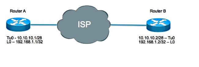
Router A:
interface loopback 0
  ip address 192.168.1.1 255.255.255.255
!
interface tunnel 0
  ip address 10.10.10.1 255.255.255.252
  tunnel source loopback0
  tunnel destination 192.168.1.2
  keepalive 5 4
Router B:
interface loopback 0
  ip address 192.168.1.2 255.255.255.255
!
interface tunnel 0
  ip address 10.10.10.2 255.255.255.252
  tunnel source loopback0
  tunnel destination 192.168.1.1
  keepalive 5 4
In this scenario, Router A performs these steps:
-
- The source is set as the local the tunnel destination, which is 192.168.1.2
- The destination is set as the local tunnel source, which is 192.168.1.1, and
- Constructs the inner IP header every five seconds where a GRE header is added with a Protocol Type (PT) of 0.
Packet generated by Router A but not sent:
IP Header
GRE
Source:192.168.1.2 Destination:192.168.1.1 PT=0
Sends that packet out of its tunnel interface, which results in the encapsulation of the packet with the outer IP header where:
- The source is set as the local the tunnel source, which is 192.168.1.1
- The destination is set as the local tunnel destination, which is 192.168.1.2, and
- A GRE header is added with PT = IP.
Packet sent from Router A to Router B:
| GRE IP Header |
GRE |
|
|||||||
| Source: 192.168.1.1 | Destination: 192.168.1.2 | PT=IP | |||||||
- Increments the tunnel keepalive counter by one.
- With the assumption that there is a way to reach the far end tunnel endpoint and the tunnel line protocol is not down due to other reasons, the packet arrives on Router B. It is then matched against Tunnel 0, becomes decapsulated, and is forwarded to the destination IP which is the tunnel source IP address on Router A.
Sent from Router B to Router A:
IP Header
GRE
Source:192.168.1.2 Destination:192.168.1.1 PT=0 - Upon arrival on Router A, the packet becomes decapsulated and the check of the PT results in 0. This signifies that this is a keepalive packet. The tunnel keepalive counter is then reset to 0 and the packet is discarded.
If Router B is unreachable, Router A continues to construct and send keepalive packets as well as normal traffic. If the keepalives do not come back, the tunnel line protocol stays up as long as the tunnel keepalive counter is less than the number of retries, which in this case is four. If that condition is not true, then the next time Router A attempts to send a keepalive to Router B, the line protocol is brought down.
In order to see keepalives in action, enable debug tunnel and debug tunnel keepalive.
Sample debugs from Router A:
debug tunnel keepalive
        Tunnel keepalive debugging is on
        01:19:16.019: Tunnel0: sending keepalive, 192.168.1.1->192.168.1.2
        (len=24 ttl=0), counter=15
        01:19:21.019: Tunnel0: sending keepalive, 192.168.1.1->192.168.1.2
        (len=24 ttl=0), counter=16
        01:19:26.019: Tunnel0: sending keepalive, 192.168.1.1->192.168.1.2
        (len=24 ttl=0), counter=17
GRE Keepalives and Unicast Reverse Path Forwarding
Unicast RPF (Unicast Reverse Path Forwarding) is a security feature that helps detect and drop spoofed IP traffic with a validation of the packet source address against the routing table. When Unicast RPF is run in strict mode (ip verify unicast source reachable-via rx), the packet must be received on the interface that the router would use in order to forward the return packet. If strict mode or loose mode Unicast RPF is enabled on the tunnel interface of the router that receives the GRE keepalive packets, then the keepalives packets are dropped by RPF after tunnel decapsulation since the route to the source address of the packet (router own tunnel source address) is not through the tunnel interface. RPF packet drops can be observed in the show ip traffic output as follows:
Router#show ip traffic | section Drop
 Drop: 0 encapsulation failed, 0 unresolved, 0 no adjacency
 0 no route, 156 unicast RPF, 0 forced drop
 0 options denied
As a result, the initiator of the tunnel keepalives brings down the tunnel due to missed keepalives return packets. So Unicast RPF must not be configured in strict or loose mode for GRE tunnel keepalives to work. For more information about Unicast RPF, refer to Understanding Unicast Reverse Path Forwarding.
IPsec and GRE Keepalives
GRE Tunnels with IPsec
GRE tunnels are sometimes combined with IPsec because IPsec does not support IP multicast packets. Because of this, dynamic routing protocols cannot run successfully over an IPsec VPN network. Since GRE tunnels do support IP multicast, a dynamic routing protocol can be run over a GRE tunnel. The GRE IP unicast packets that result can be encrypted by IPsec.
There are two different ways that IPsec can encrypt GRE packets:
- One way is with the use of a crypto map. When a crypto map is used, it is applied to the outbound physical interface(s) for the GRE tunnel packets. In this case, the sequence of steps is as follows:
- Encrypted packet reaches the physical interface.
- Packet is decrypted and forwarded to the tunnel interface.
- Packet is decapsulated and then forwarded to the IP destination in clear text.
- The other way is to use tunnel protection. When tunnel protection is used, it is configured on the GRE tunnel interface. The tunnel protection command became available in Cisco IOS Software Release 12.2(13)T. In this case, the sequence of steps is as follows:
- Encrypted packet reaches physical interface.
- Packet is forwarded to the tunnel interface.
- Packet is decrypted and decapsulated and then forwarded to the IP destination in clear text.
Both methods specify that IPsec encryption is performed after the addition of the GRE encapsulation. There are two key differences between when you use a crypto map and when you use tunnel protection:
- The IPsec crypto map is tied to the physical interface and is checked as packets are forwarded out the physical interface. The GRE tunnel has already GRE encapsulated the packet by this point.
- Tunnel protection ties the encryption functionality to the GRE tunnel and is checked after the packet is GRE encapsulated but before the packet is handed to the physical interface.
Problems with Keepalives When You Combine IPsec and GRE
Given the two ways to add encryption to GRE tunnels, there are three distinct ways to set up an encrypted GRE tunnel:
- Peer A has tunnel protection configured on the tunnel interface while Peer B has crypto map configured on the physical interface.
- Peer A has crypto map configured on the physical interface while Peer B has tunnel protection configured on the tunnel interface.
- Both Peers have tunnel protection configured on the tunnel interface.
The configuration described in Scenarios 1 and 2 are often done in a hub-and-spoke design. Tunnel protection is configured on the hub router in order to reduce the size of the configuration and a static crypto map is used on each spoke.
Consider each of these scenarios with GRE keepalives enabled on Peer B(spoke) and where tunnel mode is used for encryption.
Scenario 1
Configuration:
- Peer A uses Tunnel Protection.
- Peer B uses Crypto Maps.
- Keepalives are enabled on Peer B.
- IPsec encryption is done in tunnel mode.
In this scenario, since the GRE keepalives are configured on Peer B, the sequence events when a keepalive is generated are as follows:
- Peer B generates a keepalive packet which is GRE encapsulated and then forwarded to the phyiscal interface where it is encrypted and sent on to the tunnel destination, Peer A.
Packet sent from Peer B to Peer A:
IP Header
ESP Header
GRE IP Header
GRE Header
IP Header
GRE
SourceA DestinationB PT=0 ESP trailer
SourceB DestinationA SourceB DestinationA PT=IP - At Peer A, the GRE keepalive is received decrypted:
GRE IP Header
GRE
IP Header
GRE
SourceA DestinationB PT=0 SourceB DestinationA PT=IP
decapsulated:
IP Header
GRE
SourceA DestinationB PT=0
Then, the inner GRE keepalive response packet is routed based on its destination address which is Peer B. That means on Peer A, the packet is immediately routed back out the physical interface to Peer B. Since Peer A uses tunnel protection on the tunnel interface, the keepalive packet is not encrypted.
Therefore, packet sent from Peer A to Peer B:
IP Header
GRE
SourceA DestinationB PT=0
- Peer B now recieves a GRE keepalive response which is not encrypted on its physical interface, but because of the crypto map configured on the physical interface, it expects an encrypted packet and so drops it.
Therefore, even though the Peer A responds to the keepailves and router Peer B receives the responses, it never process them and eventually changes the line protocol of the tunnel interface to down state.
Result:
Keepalives enabled on Peer B cause the tunnel state on Peer B to change to up/down.
Scenario 2
Configuration:
- Peer A uses Crypto Maps.
- Peer B uses Tunnel Protection.
- Keepalives are enabled on Peer B.
- IPsec encryption is done in tunnel mode.
In this scenario, since the GRE keepalives are configured on Peer B, the sequence events when a keepalive is generated are as follows:
- Peer B generates a keepalive packet which is GRE encapsulated and then encrypted by the tunnel protection on the tunnel interface and then forwarded to the physical interface.
Packet sent from Peer B to Peer A:
IP Header
ESP Header
GRE IP Header
GRE Header
IP Header
GRE
SourceA DestinationB PT=0 ESP trailer
SourceB DestinationA SourceB DestinationA PT=IP - At Peer A, the GRE keepalive is received decrypted:
GRE IP Header
GRE
IP Header
GRE
SourceA DestinationB PT=0 SourceB DestinationA PT=IP
decapsulated:
IP Header
GRE
SourceA DestinationB PT=0
Then, the inner GRE keepalive response packet is routed based on its destination address which is Peer B. That means on Peer A, the packet is immediately routed back out the physical interface to Peer B. Since Peer A uses crypto maps on the physical interface, it first encrypt this packet before it forwards it on.
Therefore, packet sent from Peer A to Peer B:
IP Header
ESP Header
IP Header
GRE
SourceA DestinationB PT=0 ESP trailer
SourceB DestinationA
- Peer B now receives an encrypted GRE keepalive response whose destination is forwarded to the tunnel interface where it is decrypted:
IP Header
GRE
SourceA DestinationB PT=0
Since Protocal Type is set to 0, Peer B knows this is a keepalive response and processes it as such.
Result:
Keepalives enabled on Peer B successfully determine what the tunnel state can be based on the availability of the tunnel destination.
Scenario 3
Configuration:
- Both Peers use Tunnel Protection.
- Keepalives are enabled on Peer B.
- IPsec encryption is done in tunnel mode.
This scenario is similar to Scenario 1 in that when Peer A receives the encrypted keepalive, it decrypts and decapsulates it. However, when the response is forwarded back out, it is not encrypted since Peer A uses tunnel protection on the tunnel interface. Thus, Peer B drops the unencrypted keepalive response and does not process it.
Result:
Keepalives enabled on Peer B cause the tunnel state on Peer B to change to up/down.
Workaround
In such situations where the GRE packets must be encrypted, there are three possible solutions:
- Use a crypto map on Peer A, tunnel protection on Peer B, and enable keepalives on Peer B.
Since this type of configuration is mostly used in hub-and-spoke setups and because in such setups it is more important for the spoke to be aware of the hubs reachability, the solution is to use a dynamic crypto map on the hub (Peer A) and tunnel protection on the spoke (Peer B) and enable GRE keepalives on the spoke. This way, although the GRE tunnel interface on the hub remains up, the routing neighbor and the routes through the tunnel are lost and the alternate route can be established. On the spoke, the fact that the tunnel interface went down can trigger it to bring up a dialer interface and call back to the hub (or another router at the hub), then establish a new connection. - Use something other than GRE keepalives in order to determine peer reachability.
If both routers are configured with tunnel protection, then GRE tunnel keeaplives cannot be used in either direction. In this case, the only option is to use the routing protocol or other mechanism, such as the Service Assurance Agent, in order to discover if the peer is reachable or not. - Use crypto maps on Peer A and Peer B.
If both the routers are configured with crypto maps, the tunnel keepalives can get through in both directions and the GRE tunnel interfaces can shut down in either or both directions and trigger a backup connection to be made. This is the most flexible option.
Related Information
Revision History
| Revision | Publish Date | Comments |
|---|---|---|
4.0 |
15-Jun-2026
|
Recertification |
3.0 |
18-Apr-2025
|
Updated formatting and corrected some grammar and spelling errors. |
2.0 |
19-Dec-2022
|
Added Alt Text.
Updated Introduction, gerunds, style requirements and formatting. |
1.0 |
31-Oct-2014
|
Initial Release |
 Feedback