Introduction
This document describes how to configure Virtual LANs (VLANs) on Wireless LAN controllers (WLCs).
Prerequisites
Requirements
This procedure assumes that there is a functional DHCP server to provide IP addresses to the access points (APs) that are registered to the controller.
Components Used
The information in this document was created from the devices in a specific lab environment. All of the devices used in this document started with a cleared (default) configuration. If your network is live, ensure that you understand the potential impact of any command.
Conventions
Refer to Cisco Technical Tips Conventions for more information on document conventions.
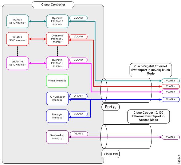
Dynamic Interfaces on WLCs
Dynamic interfaces, also known as VLAN interfaces, are created by users and designed to be analogous to VLANs for wireless LAN clients.
A controller can support up to 512 dynamic interfaces (VLANs). Each dynamic interface is individually configured and allows separate communication streams to exist on any or all of a controller’s distribution system ports. Each dynamic interface controls VLANs and other communications between controllers and all other network devices, and each acts as a DHCP relay for wireless clients associated to Wireless LANs (WLANs) mapped to the interface.
It is possible to assign dynamic interfaces to distribution system ports, WLANs, the Layer 2 management interface, and the Layer 3 ap-manager interface. It is also possible to map the dynamic interface to a backup port.
Configure zero, one, or multiple dynamic interfaces on a distribution system port. However, all dynamic interfaces must be on a different VLAN or IP subnet from all other interfaces configured on the port. If the port is untagged, all dynamic interfaces must be on a different IP subnet from any other interface configured on the port.
For information about maximum number of VLANs supported on a Cisco WLC platform, see the respective Cisco WLC platform datasheet. Cisco recommends the use of tagged VLANs for dynamic interfaces.
VLANs with WLAN controllers use this model:
Prerequisites for Configuration of Dynamic Interfaces
To configure the dynamic interface of thecontroller, use tagged VLANs for dynamic interfaces.
Restrictions on Configuration Dynamic Interfaces
These restrictions apply for the configuration of dynamic interfaces on the controller:
- Wired clients cannot access management interface of the Cisco 2504 WLC with the IP address of the AP Manager interface.
- For SNMP requests that come from a subnet that is configured as a dynamic interface, the controller responds but the response does not reach the device that initiated the conversation.
- If a DHCP proxy and/or a RADIUS source interface is used, ensure that the dynamic interface has a valid routable address. Duplicate or overlapped addresses across controller interfaces are not supported.
- Do not use ap-manager as the interface name to configure dynamic interfaces as ap-manager is a reserved name.
Configure
This section presents the information to configure the features described in this document.
Note: Use the Command Lookup Tool (registeredcustomers only) to find more information on the commands used in this document.
Catalyst Switch that Runs Cisco IOS Software
w-backbone-6#configure terminal
Enter configuration commands, one per line. End with CNTL/Z.
w-backbone-6(config)#interface gigabitethernet 8/25
w-backbone-6(config-if)#switchport
w-backbone-6(config-if)#switchport trunk encapsulation dot1q
w-backbone-6(config-if)#switchport trunk native vlan 999
w-backbone-6(config-if)#switchport trunk allowed vlan 1,81,82,171,999
w-backbone-6(config-if)#switchport mode trunk
w-backbone-6(config-if)#end
w-backbone-6#
Note: VLAN number 999 is used as native VLAN here. This means the untagged traffic that arrives at the WLC port comes from vlan 999. In this document, the WLC has management port with tagged VLAN 1, which means traffic to/from the WLC management interface goes on VLAN 1 and VLAN 999 is not used by the WLC.
WLAN Controller VLAN Configuration in GUI
Complete these steps on the WLAN controller.
-
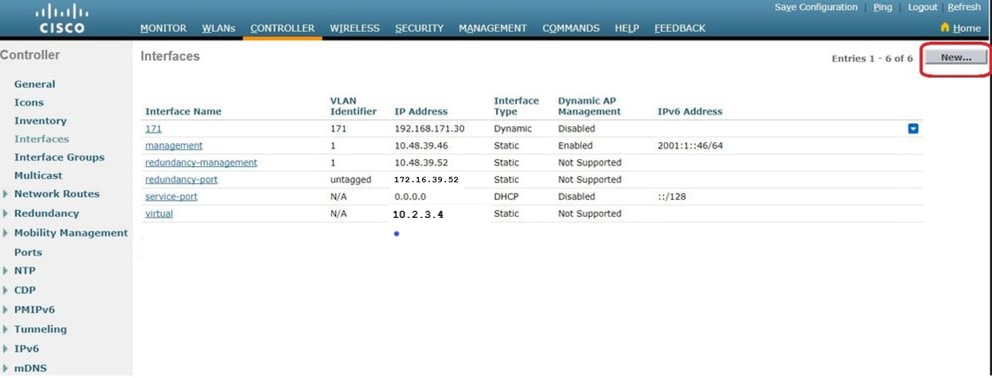
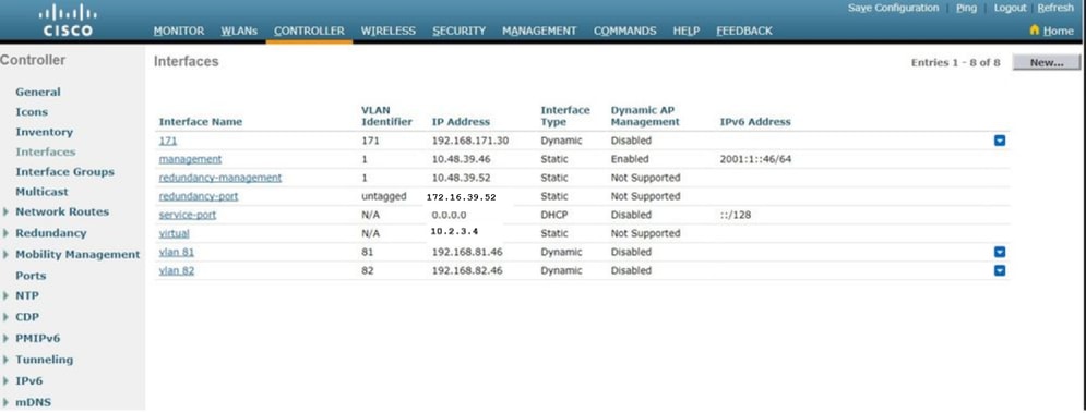
From the WLC GUI, navigate to Controller > Interfaces. The interfaces page lists all the interfaces that are configured on the WLC. In order to create a new dynamic interface, click New.
-
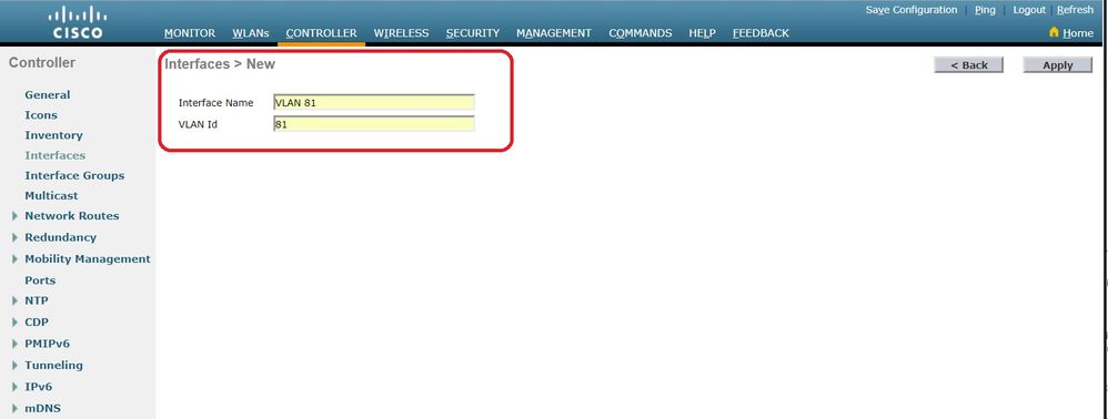
Enter the Interface Name and VLAN Identifier, and clickApply.
-
Enter the parameters specific to this VLAN. Some of the parameters include the IP Address,Netmask,Gateway, and the Primary DHCP Server IP address, and click Apply.
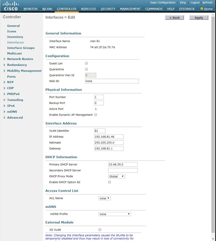
Note: The IP address assigned to this interface acts as the DHCP relay for a client to obtain an IP address from the DHCP server. For example, when a client attempts to associate to a WLAN/SSID (step 5 in this configuration) mapped to this dynamic interface, it performs a local subnet broadcast to identify the DHCP server. The controller sends a request to the DHCP server (or to itself if it is the DHCP server for the segment) with the IP address of this dynamic interface as relay IP to the DHCP server configured for this interface. The DHCP server assigns an IP address to the client from the configured DHCP scope.
Note: It is mandatory to have a valid IP address for technical reasons, but this IP address is not used unless DHCP proxy or radius interface overwrite (under WLAN config) are enabled.
Note: The Interface Name or VLAN name is used as radius attribute (airespace-interface-name) to return a VLAN name instead of number.
-
Verify the interface configuration. Click the Controller tab in the menu at the top of the window, and choose Interfaces from the menu on the left.
-
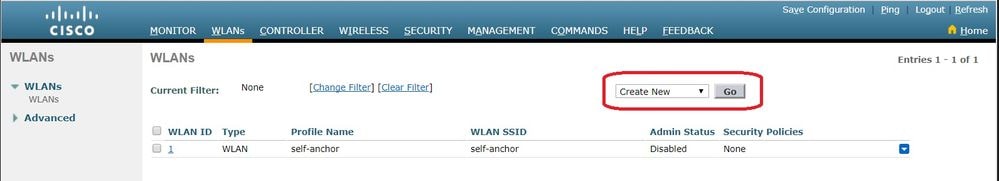
Click theWLANstab in the menu at the top of the window, and clickCreate New.
-
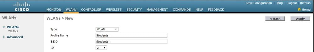
Enter the Service set identifier (SSID) andProfile Nameand clickApply.This example usesVLAN 81for ease of understanding.
-
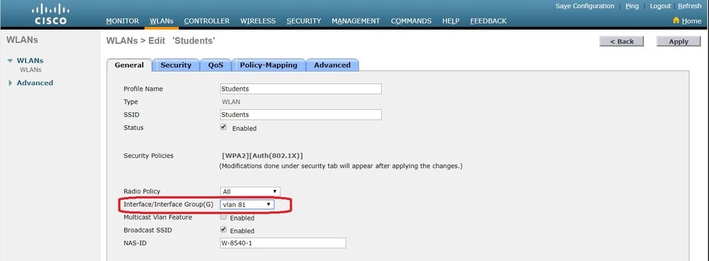
Select VLAN 81 from the Interface Namedrop-down menu at the bottom of the window, and clickApply. In this case, SSID Students is tied toInterface Name VLAN 81.
WLAN Controller VLAN Configuration in CLI
Use this section in order to configure your VLAN via command-line interface (CLI).
- Create the interface and the associated VLAN tag. The command is
config interface create interface_namevlan_id.
(W-8540-1) >config interface create "VLAN 81" 81
Note: If there is a space in the VLAN/WLAN name as is the case in this example, make sure the name is in quotes.
- Define the IP address and default gateway. The command is
config interface interface_nameIP_addressnetmaskgateway.
(W-8540-1) >config interface address dynamic-interface "VLAN 81" 192.168.81.46 255.255.255.0 192.168.81.1
- Define the DHCP server. The command is
config interface dhcp dynamic-interface<interface-name>primary<primary-server>[secondary]<secondary-server>.
(W-8540-1) >config interface dhcp dynamic-interface "VLAN 81" primary 10.48.39.5
- Issue this command in order to map the interface to a physical port:
config interface port operator_defined_interface_name physical_ds_port_number.
(W-8540-1) >config interface port "VLAN 81" 1
- Verify the interface configuration. The command is
show interface summary.
(W-8540-1) >show interface summary

 Number of Interfaces.......................... 8
 Interface Name               Port   Vlan Id        IP Address    Type           Ap Mgr Guest
 -------------------------------- ---- -------- --------------- ------- ------ -----
 171                          1      171           192.168.171.30 Dynamic       No        No
 management                  1      1              10.48.39.46   Static         Yes        No
 redundancy-management        1      1              10.48.39.52   Static         No        No
 redundancy-port              -      untagged       172.16.39.52 Static         No        No
 service-port                N/A    N/A           0.0.0.0        DHCP          No        No
 virtual                      N/A    N/A            10.2.3.4        Static         No        No
 vlan 81                      1      81             192.168.81.46 Dynamic        No        No
 vlan 82                      1      82             192.168.82.46 Dynamic        No        No
- Define the WLAN. The command is
config wlan create wlan_idname.
(W-8540-1) >config wlan create 2 Students Students
- Define the interface for the WLAN. The command is
config wlan interface wlan_idinterface_name.
(W-8540-1) >config wlan interface 2 "vlan 81"
- Verify the WLAN and the associated interface. The command is
show wlan summary.
(W-8540-1) >show wlan summary
 .
 Number of WLANs.................................. 2
 WLAN ID     WLAN Profile Name / SSID     Status         Interface Name PMIPv6 Mobility
 ------- ------------------------------------- -------- -------------------- ---------------
 1           self-anchor / self-anchor    Disabled       management    none
 2           Students / Students          Enabled        vlan 81        none

 (W-8540-1) >
Verify
Use this section to confirm that your configuration works properly.
Catalyst Switches Verification
-
Catalyst switch that runs Cisco IOS Software: show running-config interface interface_type interface_number.
w-backbone-6k#show running-config interface gigabitethernet 2/1

Building configuration...

Current configuration : 190 bytes
!
interface GigabitEthernet2/1
 no ip address
 switchport
 switchport trunk encapsulation dot1q
 switchport trunk native vlan 999
 switchport trunk allowed vlan 1,81,82,171,999
 switchport mode trunk
 end
WLAN Controller VLAN Verification
- Verify the interface configuration. The command is
show interface summary.
(W-8540-1) >show interface summary

 Number of Interfaces.......................... 8
 Interface Name               Port   Vlan Id        IP Address    Type           Ap Mgr Guest
 -------------------------------- ---- -------- --------------- ------- ------ -----
 171                          1      171           192.168.171.30 Dynamic       No        No
 management                  1      1              10.48.39.46   Static         Yes        No
 redundancy-management        1      1              10.48.39.52   Static         No        No
 redundancy-port              -      untagged       172.16.39.52 Static         No        No
 service-port                N/A    N/A           0.0.0.0        DHCP          No        No
 virtual                      N/A    N/A            10.2.3.4        Static         No        No
 vlan 81                      1      81             192.168.81.46 Dynamic        No        No
 vlan 82                      1      82             192.168.82.46 Dynamic        No        No
- Verify the WLAN and the associated interface. The command is
show wlan summary.
(W-8540-1) >show wlan summary

 Number of WLANs.................................. 2
 WLAN ID     WLAN Profile Name / SSID     Status         Interface Name PMIPv6 Mobility
 ------- ------------------------------------- -------- -------------------- ---------------
 1           self-anchor / self-anchor    Disabled       management    none
 2           Students / Students          Enabled        vlan 81        none

 (W-8540-1) >
Troubleshoot
Use this section to troubleshoot your configuration.
Troubleshoot Procedure
Complete these instructions in order to troubleshoot your configuration.
-
Ping from the WLAN controller to the default gateway that is configured on the VLAN routed interface, and then ping in the opposite direction.
-
WLAN controller:
(W-8540-1) >ping 192.168.81.1

Send count=3, Receive count=3 from 192.168.81.1

(W-8540-1) >
-
VLAN routed interface:
w-backbone-6k#ping 192.168.81.46

Type escape sequence to abort.
Sending 5, 100-byte ICMP Echos to 192.168.81.46, timeout is 2 seconds:
!!!!!
Success rate is 100 percent (5/5), round-trip min/avg/max = 1/1/1 ms
w-backbone-6k#
-
If the pings are unsuccessful, deploy a packet capture/sniffer at the switch and check in order to verify proper VLAN tagging.
Note: When you initiate the ping from your controller to a Layer 3 gateway, which is on the same subnet as your dynamic interface, the controller appears to source the ping from the dynamic interface.
 Feedback